A Compact Microstrip Patch Antenna using
Metamaterial
Nikhil Kulkarni
#1,
G. B. Lohiya
*2#1Department of Electronic and Telecommunication, Mumbai University, India *2Department of Electronic and Telecommunication, Mumbai University, India
Abstract — In this paper, a metamaterial based compact multiband microstrip antenna is proposed which can give high gain and directivity. Metamaterials are periodic structures and have been intensively investigated due to the particular features such as ultra-refraction phenomenon and negative permittivity and/or permeability. A metamaterial based microstrip patch antenna with enhanced characteristics and multi band operation will be investigated in this work. The multiple frequency operation will be achieved by varying the capacitance of the metamaterial structure with the help of metallic loadings placed in each metamaterial unit cells. The potential impacts will be miniaturization, reduced cost and reduced power consumption since multiple antennas operating at different frequencies are replaced by a single antenna which can operate at multiple frequencies. The proposed microstrip patch antenna will have its frequencies of operation in the L, S and C bands. The proposed structure is simulated using Agilent Advanced Design System (ADS) 2011.05. It is then fabricated on the FR4 substrate and the performance of the fabricated antenna is measured using the Vector Network Analyser (VNA).
Keywords — Metamaterial, Microstrip Antenna, Bandwidth, Tunability, Frequency Range, Gain.
I. INTRODUCTION
In wireless applications different antennas are required for different applications [1]. This increases the size of the wireless communication. Also high gain and high bandwidth is needed in any communication systems. To achieve all these features simultaneously in a single device, the concept of metamaterial is used along with microstrip antenna (MSA) [2]-[5]. If the size of microstrip antenna is large, then it provides high gain and vice versa [2].
II. BASIC MICROSTRIP PATCH ANTENNA
A microstrip patch antenna is one of the most commonly utilized printed antennas. It consists of a radiating patch on one side of a dielectric substrate and a ground plane on the other side. An MSA can be of any shape, but rectangular shape MSA is most commonly used. Microstrip patch antenna, in their most basic form, benefits from their low profile, low cost, simplicity, and omnidirectional radiation pattern. Narrow bandwidth is one of the main
disadvantages of a microstrip patch antenna. The antenna has to operate over a wide bandwidth in case of multichannel applications. But at a given time it has to operate over only a small bandwidth to cover a single channel. Radiation from the MSA can occur from the fringing fields between the periphery of the patch and the ground plane. To enhance the fringing fields from the patch, which account for the radiation, the width w of the patch is increased. The fringing fields are also enhanced by decreasing the
r
or by increasing the substrate thickness h [1]. The basic structure of MSA is given in Fig. 1.Fig 1. Microstrip Antenna
The Width and Length of MSA will be given by [6], w = [c/2fo (√ (
r + 1)/2)] … (1)Ɛeff = [(
r + 1)/2] + {[(
r - 1)/2] * [1/√1 + 12(h/w)]} ... (2)l = (c/2f0√ Ɛeff) – 0.824h {[(Ɛeff + 0.3) * ((w/h) +
0.264)]/ [(Ɛeff – 0.258) * ((w/h) + 0.8)]}
...(3) where,
Velocity of light (c) = 3*108 m/s, f0 = Centre frequency (GHz)
Dielectric constant (Ɛr) = 4.28,
Ɛeff = Effective dielectric constant,
Height (h) = 1.57 mm.
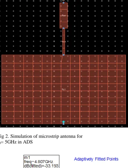
Using equations (1), (2) and (3) the MSA design for centre frequency (f0) 5GH for which
l = 13.76mm. w = 18.24mm. and is shown in Fig. 2.
The simulation result of this microstrip patch antenna is given in Fig. 3.
Fig 2. Simulation of microstrip antenna for f0= 5GHz in ADS
Fig 3. Simulation result output for f0= 5GHz
The disadvantages of Microstrip Patch Antenna are:-
Limited bandwidth (usually 1 to 5%). Low gain.
Low power handling.
To overcome this drawback metamaterial plays an important role [1]-[2].
III.METAMATERIAL
Metamaterials are artificial materials synthesized by embedding specific inclusions in host
media and they exhibit the properties of either negative permittivity or permeability. If both negative permittivity and negative permeability happen at the same time, then the composite exhibits an effective negative index of refraction and is referred to as left handed metamaterials (LHMs) [7]-[9]. 4 Permittivity, Permeability and Refractive Index graph for metamaterial is shown in Fig. 4.
Fig 4. Permittivity, Permeability and Refractive Index graph
The idea of metamaterial was first proposed theoretically by Veselago in 1968 [7]. The negative permittivity was demonstrated and theorized with an array of metallic wires in 1996 by Pendry.
layer either as substrate or superstrate.
A. Metamaterial SSR Structure
The split ring resonator (SRR) structure as shown in Fig. 5 is the metamaterial substrate used as a superstrate on the microstrip patch for tuning. The outer ring of the structure measures 7mm in length as well as the width. Similarly, the inner ring measures 5mm in length and width. The opening measures 1mm in width and 0.5mm in length. Each microstrip patch has three SSR structure placed on it and then the antenna is simulated. The loadings placed in the SRR structure are small square measuring 0.5 mm each which helps in tuning [10].
Fig 5. Proposed metamaterial SSR structure a) Metamaterial without load
b) Metamaterial with loading 1 c) Metamaterial with loading 2 d) Metamaterial with loading 3
B. Metamaterial-based Tunability
Metamaterials find a lot of applications in devices, which are operating in microwave regime. To add flexibility and controllability to these devices, the researchers started working for tunable metamaterials [11]. The review is scrutinizing the methods, which can be integrated with a microstrip patch antennas. In the following way, the approaches to design tunable metamaterial is categorized, which can be incorporated in the design of a microstrip patch antennas:
Tunability by incorporating varactor diode or PIN diodes in the metamaterial
Tunability by varying the structure of SRR
IV.METAMATERIAL BASED MULTIBAND
MICROSTRIP PATCH ANTENNA
In conventional microstrip patch antenna, to achieve multiband operation different antennas are required [1]. In proposed metamaterial based multiband MSA, even a single patch out of the four patch in [12] can be used. The design of Metamaterial Based Microstrip Antennas is done in three parts: first the conventional MSA is simulated and the reconfigurability is tested, then the antenna is tested with metamaterial superstrate to have increase gain [3] and bandwidth [13]-[14] then the individual patches with metamaterial are simulated to test the multiband operation.
The proposed design of multiband microstrip patch antenna covers L, S and C band in electromagnetic spectrum. To increase the gain and bandwidth, metamaterial is added to the antenna [5]. The base patch of microstrip antenna includes main radiator and four sub-patches placed on FR-4 substrate with relative permittivity =4.4 and height of a substrate h =1.57mm. The metamaterial substrate is placed on top of this patch leaving an air gap of 1mm. The total volume of the microstrip antenna design is 50x50x1.57 mm3 [12]. Software used for simulation of antenna design is Agilent Advanced Design System (ADS) 2011.05. It supports Momentum as well as FEM mode of simulation.
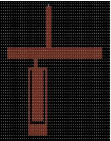
As already stated, single slotted patch is sufficient enough for the multiband operation [12]. Further (using patch 2) simulation shown only with one MSA is shown in Fig. 6. The results of the simulation and measured results are shown in the Fig. 7 and 8 respectively.
Fig 7. Simulation results of sub-patch 2
Table 1 Simulated result for frequency and return loss of MSA sub patch 2
Frequency (GHz)
Return Loss (dB)
Without Metamaterial
1.054 -17.611
1.57 -13.970
1.949 -17.007
3.441 -15.68
Fig 8. Measured result of sub patch 2
Table 2 Measured result for frequency and return loss of sub-patch 2 without loading
Frequency (GHz)
Return Loss (dB)
Without Metamaterial
1.16 -9.15
2.12 -25.27
3.62 -18.74
The simulated and measured return loss obtained is tabulated in table 1 and 2.
To achieve high gain metamaterial is placed above microstrip patch antenna [3]-[5], as shown in Fig. 9. The results of the simulation and measured results are shown in the Fig. 10 and 11 respectively.
Fig 9. Sub-patch 2 with metamaterial loading 21
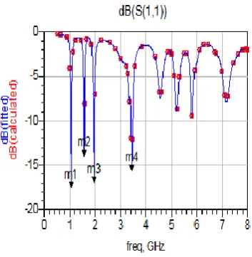
Fig 10. Simulation results of sub-patch 2 with loading 21
Table 3 simulated results for frequency and return loss of sub-patch 2 with loading 21
Frequency (GHz)
Return Loss (dB)
Load 21
1.546 -15.891
1.897 -31.051
3.329 -20.065
5.751 -10.661
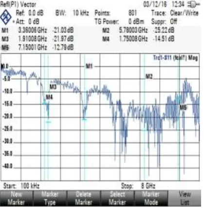
Fig 11. Measured result of sub patch 2 with loading 21
Table 4 measured result for frequency and return loss of sub-patch 2 with loading 21
Table 4 measured result for frequency and return loss of sub-patch 2 with loading 21
Frequency (GHz)
Return Loss (dB)
Load 21
1.75 -14.51
1.901 -21.97
3.36 -21.03
5.78 -25.22
7.15 -12.79
From Table 1, 2, 3 and 4, it is observed that return loss is more negative for MSA with metamaterial. Return loss indicate the gain, to achieve higher gain, return loss should be more negative. Further, the different loading helps in getting multiband operation. Thus the overall size of the patch is just equivalent to sub patch 2 [12].
V. CONCLUSION
The proposed microstrip antenna patch antenna with metamaterial gives a multiband operation, covering the frequency range of L, S and C bands as compared to conventional microstrip patch antenna which cover only L and S bands. By analysing the simulation result, it is found that the gain is also increased. Further the size of antenna is also reduced. Such a compact multiband microstrip antenna can be used for all the wireless applications thus saving space and cost.
REFERENCES
[1] Girish Kumar and K. P. Ray, Broadband Microstrip Antenna, Artech House.
[2] V. I. Slyusar, “Metamaterials on Antenna Solutions,” in Proc. International Conf. on Antenna Theory and Techniques, pp. 19-24, 6-9 Oct. 2009.
[3] H. A. Majid, M. K. A. Rahim, and T. Masri, “Microstrip Antenna's Gain Enhancement Using Left-Handed Metamaterial Structure,’ Progress In Electromagnetics Research M, Vol. 8, 235-247, 2009.
[4] Ahmad A. Sulaiman, Ahmad S. Nasaruddin, et.al., “Bandwidth Enhancement in Patch Antenna by Metamaterial Substrate,” European Journal of Scientific Research Vol.44 No.3 (2010), pp.493-501, 2010. [5] R. K. Lou, T. Aribi, and C. Ghobadi, “Improvement of
Characteristics of Microstrip Antenna Using of Metamaterial Superstrate,” in Proc. International Conf. on Communications Engineering, 22-24 Dec. 2010.
[6] George Casu1, Cătălin Moraru, Andrei Kovacs,” Design and Implementation of Microstrip Patch Antenna Array,” IEEE, 2014.
[7] V. Veselago, L. Braginsky, V. Shklover and C. Hafner, “Negative Refractive Index Materials,” J. Comput. Theor. Nanosci., Vol. 3, No. 2, 2006.
[8] Richard D. Averitt, Introduction to Metamaterials. Boston University, Boston.
[9] Kyu-Chang LEE, Seung-In YANG, “High Gain Patch Antenna for 2.4GHz using Metamaterial Superstrate,”
Supplement Journal of Measurement Science and Instrumentation, Vol.1, 2010.
[10] Adnan SONDAS, Mustafa Hikmet Bilgehan UCAR, Yunus Emre ERDEMLI, “Tunable SRR-based substrate for a microstrip patch Antenna,” Turk J Elec Eng & Comp Sci, Vol.20, No.1, 2012.
[11] M. Borhani, P. Rezaei, and A. Valizade, “Design of A Reconfigurable Miniaturized Microstrip Antenna for Switchable Multiband Systems,” IEEE Antennas and Wireless Propagation, 2015.
[12] S. Dhamankar and U. P. Khot, “Design of Reconfigurable and Tunable Multiband Patch Antenna for Wireless Devices,” in Proc. International Conf. on Recent Advances & Challenges in Engineering & Management (RACEM-2014), Mumbai, 3-4, pp.1-3, April, 2014.
[13] Ning Zhu and Richard W. Ziolkowski, “Active Metamaterial-Inspired Broad-Bandwidth, Efficient,” Electrically Small Antennas, IEEE Antennas and Wireless Propagation Letters, VOL. 10, 2011.