RESEARCH ARTICLE
EVALUATION THE EFFECT OF DIFFERENT SPRUE SHAPES ON SOME OF THE PHYSICAL
AND MECHANICAL PROPERTIES OF CASTING ALLOYS
*Maryam S. Alallak and Ihab Nafaa Yassen
Prosthodentic Department, Health Techncal College, Middle Technical University, Iraq
ARTICLE INFO
ABSTRACT
Statement of Problem: Sprue design is a factor that controls the velocity and adequate supply of metal to the mold. Currently various manufacturers recommend different sprue design, which have not been advocated in textbooks and literature is lacking for their routine applications. Purpose: The purpose of the present study was to evaluate the marginal fit and surface roughness by comparing between four sprue Design. Materials and Methods: Part I of the study determined marginal fit of base ceramometal crowns with the use of phosphate bonded investment. Stainless steel metal die was used and four sprue shapes (Group A-cylinder, Group B-Square, Group C-bottle neck D-conical) were evaluated. 40 stone die were made, 10 wax patterns for each sprue design were waxed up, invested with phosphate bonded investment material and castings done with centrifugal casting machine by the same operator under standardized protocols. The casting coreFit on the respective die and .margin on digital microscope evaluation. Data were tabulated and statistically analyzed with 1-way ANOVA followed By Student‘t’ test.Part IIused AFM microscope to evaluate the surface roughness of casting disc made with same techniques as Part I. Results: For margin gap: The results differed significantly (P <0.0001) ) between the Groups with maximum defects in the castings of Group A followed in decreasing order by Group B, Group C and Group D. When comparing between the Groups (P <0.05) the gap in Groups B, C and D was significantly lower than Group A. For surface roughness results differed significantly (P <0.0001) ) between the Groups with maximum defects(roughness) in the castings of Group C followed in decreasing order by Group A, Group B and Group D. When comparing between the Groups (P <0.05) the defects in Groups C and A was significantly higher than Group Band D. Conclusion: Conical with flared point of attachment sprues produced most satisfactory margin fit and surface roughness, meanwhile the cylinder without reservoir produced maximum defect in margin gap and surface roughness.
Copyright © 2019,Maryam Alallak and Ihab Nafaa Yassen. This is an open access article distributed under the Creative Commons Attribution License, which permits unrestricted use, distribution, and reproduction in any medium, provided the original work is properly cited.
INTRODUCTION
Dental casting alloys have an important responsibility task in the field of prosthodontics. Gold -based alloys with over 70 weight percentage (wt%) composition, were it's the only type of alloy used for fixed prostheses, with or without ceramic veneers before the deregulation of the price of gold in the United States in the early 1970’s, since then the compositions and types of casting alloys available to the dental practitioner
have changed significantly over the past 35 years. Precious
metals and their alloys have been considered an ideal restorative material due to their excellent properties such as biocompatibility, castability, percentage elongation, and burnish ability, capacity to take a high polish, and resistance to tarnish and corrosion. However, over time for economic reasons, base metal alloys have become widely used, limiting
the routine use of precious alloys in dental practice (Chandra
et al., 2011). It bears similar properties to the gold alloys besides other properties like low specific gravity and cost.
Therefore, Co-Cr and Ni-Cr alloy and its types have successful
role in the dental prosthesis (Palaskar et al., 2010). The
success of any dental cast restoration depends upon the marginal adaptation (fitness) of casting to the underlying tooth structure. The accuracy of the marginal fit is essential for its longevity and a healthy periodontium. Good marginal adaptation is necessary to achieve better mechanical,
biological and esthetic prognosis (Alex et al., 2015). During
any step of casting procedure like spruing, investing, wax elimination and Solidification. Structural flaws be can accrue. The shape of sprue can be consider the most important factor which have main influences to the adequate supply and fluidity of molten alloy to the mold cavity. Recently, some manufacturers advocated various sprue shape which have not been defended in textbook and the references about their ordinary used are absences. (Viswambaran and Grawal, 2013). In the same time, the success of the fixed restoration depends upon many factors and one of them is the close adaptation at the margins of the cast restorations. Discrepancy at the margin causes accumulation of plaque, infiltration of bacteria and
ISSN: 0976-3376
Vol. 10, Issue, 02, pp.9395-9403, February,Asian Journal of Science and Technology 2019SCIENCE AND TECHNOLOGY
Article History:
Received 10th November, 2018
Received in revised form 18th December, 2018
Accepted 14th January, 2019
Published online 28th February, 2019
gradual dissolution of the luting cements and finally may cause the failure of the restoration, marginal discrepancy related to the preparation of wax pattern, the property of alloy used, defect in the casting process, release of stress du
and the properties of the investment. But the most evident reason for marginal discrepancy is the inherent nature of shrinkage of molten metal on solidification. But this can be compensated by expanding the mold space which is achieved through the expansible properties of the investment, another considerable factor of the cast restoration margin evenness / fineness is the surface roughness. Contact between the inner and outer surface of the crown leads to form the margin of casting crown, and here, the occurrence and ratio of surface roughness plays an important role in making the margin smooth or irregular.Roughness in the internal surface or a small rough nodule can result in marginal gap width and can limit uniform space for luting cement (Tandon
However, dental laboratory technicians always thought to which technique that produced acceptable result with minimum defects, therefore, in this study was designed to, improve the properties of the base metal alloys is an on research leading to various modifications in their fabrication procedure – which include the use of four different sprue shape with various point of attachment to the wax pattern. And to find some solves to prevent problems or reduce it
way.
MATERIALS AND METHODS
This invitro study was carried out to evaluate the ability of four sprue shapes (Group A: cylinder type, Group B: Square type, Group C: bottle neck type and Group D: conical type), on marginal fit and surface roughness of Nickel
crowns made with conventional casting technique.
Part I: Determination the ability of four sprue shapes on
marginal fit of Nickel chromium crowns conventional casting technique.
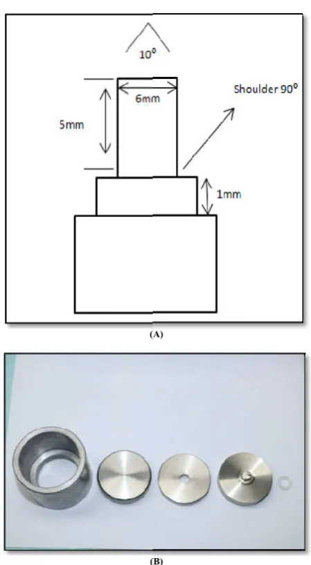
A stainless steel master die was fabricated to make standardized wax pattern crowns as per the study of
et al., 2014).The master die simulated crown preparation with 10 degree total axial wall taper. The height of the die and its occlusion diameter were (6mm) and the finish line was 90degree shoulder and (1mm) in width. Stainless steel ring (spacer) 1mm in height was fabricated to accurately fit on the shoulder of the die The use of a Spacer between the margins of the wax pattern and the shoulder of the die made it possible to detect both expansion and shrinkage discrepancies at the marginal areas of the castings. Stainless steel former that had an opening in the center 1mm larger than the die in all dimension was fabricated on which the die could be accurately position. And by using the low expansion die (Protechno. Spain), the stainless steel die was duplicated (Figure 1).
Fabrication of wax pattern
The stainless steel former was place inside the mold container in intimate contact with base of the mold and the inlay wax put in the wax pot thermostatic controlled and the pot is switched on according to the manufacture to make sure that all wax used in this stage of procedure melted at same degree of temperature. Then fill the former with molten wax.
9396 Maryam Alallak and Ihab Nafaa Yassen, Evaluation the effect of different sprue shapes on some of the physical and mechanical properties of casting alloys
gradual dissolution of the luting cements and finally may cause the failure of the restoration, marginal discrepancy related to the preparation of wax pattern, the property of alloy used, defect in the casting process, release of stress during casting and the properties of the investment. But the most evident reason for marginal discrepancy is the inherent nature of shrinkage of molten metal on solidification. But this can be compensated by expanding the mold space which is achieved the expansible properties of the investment, another considerable factor of the cast restoration margin evenness / fineness is the surface roughness. Contact between the inner and outer surface of the crown leads to form the margin of ere, the occurrence and ratio of surface roughness plays an important role in making the margin smooth or irregular.Roughness in the internal surface or a small rough nodule can result in marginal gap width and can ndon et al., 2014). However, dental laboratory technicians always thought to which technique that produced acceptable result with minimum defects, therefore, in this study was designed to, to improve the properties of the base metal alloys is an on-going esearch leading to various modifications in their fabrication which include the use of four different sprue shape with various point of attachment to the wax pattern. And to find some solves to prevent problems or reduce it in a better
This invitro study was carried out to evaluate the ability of four sprue shapes (Group A: cylinder type, Group B: Square type, Group C: bottle neck type and Group D: conical type), on marginal fit and surface roughness of Nickel chromium crowns made with conventional casting technique.
the ability of four sprue shapes on chromium crowns made with
A stainless steel master die was fabricated to make ardized wax pattern crowns as per the study of (Tandon
The master die simulated crown preparation with 10 degree total axial wall taper. The height of the die and its occlusion diameter were (6mm) and the finish line was d (1mm) in width. Stainless steel ring (spacer) 1mm in height was fabricated to accurately fit on the shoulder of the die The use of a Spacer between the margins of the wax pattern and the shoulder of the die made it possible to hrinkage discrepancies at the Stainless steel former that had an opening in the center 1mm larger than the die in all dimension was fabricated on which the die could be accurately position. And by using the low expansion die stone Spain), the stainless steel die was duplicated
The stainless steel former was place inside the mold container in intimate contact with base of the mold and the inlay wax put thermostatic controlled and the pot is switched on according to the manufacture to make sure that all wax used in this stage of procedure melted at same degree of
Then fill the former with molten wax.
(A)
(B)
Figure1. A-master die B
Carefully inverted the lubricated master die on to the Stainless steel former. With the rubber spacer in its place on the die. Then held the assembly together for (1 minute) with finger press, after cooling completely about (1 minute)
former together was separated from the container by pushing the base upward, the former separated from die and all the extra wax was trimmed from the shoulder by using PKT no.4 carver, and the wax patterns removed from the stainless steel master die together with spacer. The internal surface was thoughtfully exammed in a digital microscope (20X magnification) for any defects. The wax pattern was then rested on its respective stone die. The wax pattern with (1mm) thickness at all axial and occl
(2).
FiG. 2. fabrication of wax pattern A former B-Master die inverted on former C
die from former D- Intimate contact between pattern and rubber spacer E-Pattern on master die
Evaluation the effect of different sprue shapes on some of the physical and mechanical properties of casting alloys
(A)
(B)
master die B- stainless steel mold
Carefully inverted the lubricated master die on to the Stainless With the rubber spacer in its place on the die. Then held the assembly together for (1 minute) with finger press, after cooling completely about (1 minute). The die and former together was separated from the container by pushing the base upward, the former separated from die and all the extra wax was trimmed from the shoulder by using PKT no.4 carver, and the wax patterns removed from the stainless steel ter die together with spacer. The internal surface was thoughtfully exammed in a digital microscope (20X magnification) for any defects. The wax pattern was then rested on its respective stone die. The wax pattern with (1mm) thickness at all axial and occlusal walls, as shown in Figure
FiG. 2. fabrication of wax pattern A-Melted wax inside the Master die inverted on former C-Separated master Intimate contact between pattern and Pattern on master die without spacer
A total of 40 wax patterns were divided into four groups
Group (A): 10 samples investigate the effect of cylinder sprue
shape with graduated point of attachment
Group (B): 10 samples investigate the effect of square sprue
shape with straight point of attachment
Group(C): 10 samples investigate the effect of bottle neck
sprue shape with constricted point of attachment
Group (D): 10 samples investigate the effect of conical sprue
shape, with flared point of attachment
The wax pattern seat on it respective stone die, and distance between the two margins was measured (Four measurements) were made using digital microscope (100X)
and the mean value was used for calculations,
(Konstantoulakis et al., 1998; Tandon et al., 2014).
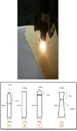
Fabrication of four sprue design
The most accurate polymer mold was designed .It
four separated mold cavities according to sprues shape experimented in this study, in computer byusing CNC technique (Computer numerical control) Figure
Fig. 3. Diagram of dimensions of experimental sprueA with graduated B-square with straight C-bottle neck with
constructed D-conical with flared point of attachment
A total of 40 wax patterns were divided into four groups
10 samples investigate the effect of cylinder sprue shape with graduated point of attachment
10 samples investigate the effect of square sprue t point of attachment
10 samples investigate the effect of bottle neck sprue shape with constricted point of attachment
10 samples investigate the effect of conical sprue
, with flared point of attachment.
The wax pattern seat on it respective stone die, and the distance between the two margins was measured (Four measurements) were made using digital microscope (100X)
and the mean value was used for calculations,
2014).
most accurate polymer mold was designed .It consist of four separated mold cavities according to sprues shape experimented in this study, in computer byusing CNC
Figure (3).
Fig. 3. Diagram of dimensions of experimental sprueA-cylinder bottle neck with conical with flared point of attachment
The wax pattern was spruced while it was seated on the stone die to minimize distortion. One end of the spur was attached to the pattern at an angle of 45º.at predetermined site
then investing using phosphate bonded investment material and casting with conventional casting techniquein centrifuge casting machine.Then the intaglio surface of each casting was examined under the digital microscope(x10 magnification) and all apparent oxide, residues and nodules were removed with No.½ or No.1round carbide bur. Then cleaned with distilled water in an ultrasonic cleaner for 12 minute and then dried.
(Tandon et al., 2014; konstantoulakis
Measurements of marginal gap
The constant load of (5000g) equal to (5kg) equal to the biting force in patients mouth (5000 gm),were applied on the occlusal surface of each casting for (10 sec.) while the castings was seated on it respective stone die
Index groove on the occlusal surface of stone die to prevent change in place of the casting and to make sure that the casting crown seating on the similar position as the wax pattern
(Konstantoulakis et al., 1998).
Fig. 4. Measuring margin gap
respective stone dieB-Metal core at 100Xmagnification sample parts 1-Metal 2- space occupied by spacer 3
core image in process option of image J program
Part II: Evaluation the ability of four sprue shapes on surface
roughness of Nickel chromium castingsdi conventional casting technique.
40 disk-shaped, patterns, prepared from technique that used1sheets of base plate wax (length 19 cm, width 9 cm, 1.5 mm thickness), that punched by a copper ring, 15 mm in diameter, to obtain a disc wax pattern
(Figure 5). Then it will be grouped, sprued
casted follow the same sequences steps that consider in part I of this study. Except that the only difference from part I was thatthe castings were not sandblasted but
taken not to expose the surface being tested.
cleaned with plastic hand instruments, and then placed in a ultrasonic cleaner for 12 minutes.
were removedwith a cleaning solution
Konstantoulakis et al., 1998).
Fig. 5. copper ring punched on 1 sheet of base plate wax
The wax pattern was spruced while it was seated on the stone minimize distortion. One end of the spur was attached to the pattern at an angle of 45º.at predetermined site, the pattern then investing using phosphate bonded investment material and casting with conventional casting techniquein centrifuge e.Then the intaglio surface of each casting was examined under the digital microscope(x10 magnification) and all apparent oxide, residues and nodules were removed with No.½ or No.1round carbide bur. Then cleaned with distilled r for 12 minute and then dried.
2014; konstantoulakis et al., 1998).
Measurements of marginal gap
constant load of (5000g) equal to (5kg) equal to the biting force in patients mouth (5000 gm),were applied on the each casting for (10 sec.) while the castings
seated on it respective stone die (Tandon et al., 2014).
Index groove on the occlusal surface of stone die to prevent change in place of the casting and to make sure that the casting milar position as the wax pattern
As show in Figure (3-23).
in metal core A- Metal core on Metal core at 100Xmagnification sample space occupied by spacer 3- stone die C- Metal core image in process option of image J program
Evaluation the ability of four sprue shapes on surface roughness of Nickel chromium castingsdisc made with conventional casting technique.
shaped, patterns, prepared from technique that used1sheets of base plate wax (length 19 cm, width 9 cm, 1.5 mm thickness), that punched by a copper ring, 15 mm in
diameter, to obtain a disc wax pattern, (Bedi et al., 2008), as
Then it will be grouped, sprued, invested, and casted follow the same sequences steps that consider in part I Except that the only difference from part I was thatthe castings were not sandblasted but instead. Care was taken not to expose the surface being tested. And carefully cleaned with plastic hand instruments, and then placed in a ultrasonic cleaner for 12 minutes. Investment material residues
removedwith a cleaning solution (Bedi et al., 2008;
Testing the specimen for surface roughness
Quantitative evaluation of surface roughness was done study by using a surface roughness tester
Microscope (AFM) (Erdemir et al., 2014)
verify the surface topography of thespecimen of all groups
RESULTS
The results of this study were analyzed statistically using SPSS version 11.5 and analysis of variance ANOVA with Tukey and Games hawell test for both inter and intra group's comparison summarized in Tables and Figures (1) to (4
listed in appendix I-V.
Table 1. Descriptive Statistics of the mean margin gap (µm) and Standard Deviation in each wax core group
Sprue type Mean Std. Deviation
Cylinder 48.2941 4.08106
Square 42.9397 7.98865
Bottle-neck 49.4203 1.65734
Conical 48.8049 2.06975
Total 47.3647 5.30955
Fig. 1. Bar- chart showing the mean margin gap (µm) of all wax core groups
Marginal Fitness
Wax Core Measurement: In Table and Figure (1) the
marginal fitness among the wax pattern of four sprue designs showed that the highest mean value of marginal discrepancy noted for experimental conical sprue type with flared point of attachment (group D), which was (49.4203 um),
standard deviation of (1.65734), descending by
of marginal discrepancy for experimental bottle neck sprue type with constricted point of attachment (group C) (48.8049 um) and standard deviation of (2.06975). Then the mean value of experimental cylinder sprue type with gradual point of attachment(group A) was (48.2941um) and the calculated standard deviation of (4.08106).
Table 2. Comparing the mean margin gap (µm) among different wax core groups using
(I) Sprue Type (J) Sprue Type
Cylinder Square
Bottle-neck Conical
Square Bottle-neck
Conical
Bottle-neck Conical
*The mean difference is high significant at .001 level - The mean difference is non-significant at .05 levels
9398 Maryam Alallak and Ihab Nafaa Yassen, Evaluation the effect of different sprue shapes on some of the physical and mechanical properties of casting alloys
Testing the specimen for surface roughness
Quantitative evaluation of surface roughness was done inthis using a surface roughness testerAtomic Force that was used to verify the surface topography of thespecimen of all groups
The results of this study were analyzed statistically using SPSS version 11.5 and analysis of variance ANOVA with Tukey and Games hawell test for both inter and intra group's comparison (1) to (4-7).All data were
of the mean margin gap (µm) and Standard Deviation in each wax core group
Std. Deviation N
4.08106 40
7.98865 40
1.65734 40
2.06975 40
5.30955 160
chart showing the mean margin gap (µm) of all wax
In Table and Figure (1) the marginal fitness among the wax pattern of four sprue designs showed that the highest mean value of marginal discrepancy noted for experimental conical sprue type with flared point of attachment (group D), which was (49.4203 um), and the descending by the mean value of marginal discrepancy for experimental bottle neck sprue type with constricted point of attachment (group C) (48.8049 um) and standard deviation of (2.06975). Then the mean value xperimental cylinder sprue type with gradual point of attachment(group A) was (48.2941um) and the calculated
While the lowest mean value of the marginal discrepancy was recorded for experimental square sprue type with straight point of attachment (group B) was noted as (42.9397) um and standard deviation of (7.98865). All results were analyzed by ANOVA test and mean standard deviation were depended for comparison among groups. The null Hypothesis that the error variance of the dependent variable is equal across groups. Table (2) Games Howell test for multiple comparison among the wax measurement, there is no
(P>0.05) among cylinder and bottle neck, cylinder and conical, Bottle neck and Conical. While there is a
difference in mean (P<0.01) between square
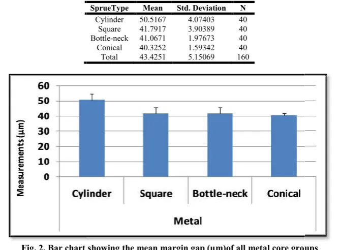
Metal Core measurement: Table and
the descriptive statistics with the mean and standard deviation of marginal discrepancy among the metal core of four sprue type designs in ANOVA test. The highest mean value of marginal discrepancy noted for experimental cylinder sprue type (Group A) of (50.5167um), and the calculated standard deviation of (4.07403). Descending by
marginal discrepancy for experimental square sprue type (Group B), which of (41.7917um) an
(3.90389) then the mean value of marginal discrepancy for experimental bottle neck sprue type (Group C) of (41.0671 um) and the standard deviation of( 1.97673) while the lowest mean value was noted in conical
(40.3252um) and standard deviation of (1.59342).The null hypothesis that the error variance of the dependent variable is equal across groups. Table (4) Show Games Howell test for multiple comparisons among the metal core Measurement. Differences were'' non- significant difference in mean (P>0.05)'' among square and bottle neck, square and conical bottle neck and conical. While high significant differences (P≤0.001) were documented between cylinder with other groups.
Comparisons of wax to metal core measur
figure (5) show the one- way ANOVA test comparison between wax core to metal core of
type groups there is non- significant difference( P>0.05) in square group, there is a significant difference (P<0.05) in cylinder group, while a high significant difference (P
was reported in bottle neck and conical
Surface roughness
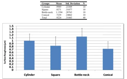
In Tables and Figure (6).The descriptive statistics for surface roughness revealed that the highest mean surface roughness for bottle neck sprue type (1.1394um) with a standard deviation of (.28763). Descending by
cylinder sprue type (.9989um) with a standard deviation of (.23309) then the mean value of square sprue type (.8271um) with a standard deviation of (.31077).
Table 2. Comparing the mean margin gap (µm) among different wax core groups using
Mean Difference (I-J) Std. Error Sig.
Lower Bound
5.3543* 1.41839 .000
-.5109- .72352 .894
-1.1262- .69645 .378
5.8652* 1.30482 .000
6.4805* 1.29001 .000
-.6154- .41925 .462
The mean difference is high significant at .001 level significant at .05 levels
Evaluation the effect of different sprue shapes on some of the physical and mechanical properties of casting alloys
While the lowest mean value of the marginal discrepancy was recorded for experimental square sprue type with straight point of attachment (group B) was noted as (42.9397) um and eviation of (7.98865). All results were analyzed by ANOVA test and mean standard deviation were depended for comparison among groups. The null Hypothesis that the error variance of the dependent variable is equal across groups. for multiple comparison among the wax measurement, there is no –significant difference (P>0.05) among cylinder and bottle neck, cylinder and conical, While there is a high significant between square and other groups.
Table and Figure (3) represents the descriptive statistics with the mean and standard deviation of marginal discrepancy among the metal core of four sprue type designs in ANOVA test. The highest mean value of discrepancy noted for experimental cylinder sprue A) of (50.5167um), and the calculated standard Descending by the mean value of marginal discrepancy for experimental square sprue type B), which of (41.7917um) and standard deviation of (3.90389) then the mean value of marginal discrepancy for ue type (Group C) of (41.0671 and the standard deviation of( 1.97673) while the lowest mean value was noted in conical sprue type (Group D) and standard deviation of (1.59342).The null hypothesis that the error variance of the dependent variable is 4) Show Games Howell test for multiple comparisons among the metal core Measurement. significant difference in mean (P>0.05)'' among square and bottle neck, square and conical, bottle neck and conical. While high significant differences ≤0.001) were documented between cylinder with other
Comparisons of wax to metal core measurement: Table and
way ANOVA test comparison between wax core to metal core of each experimental sprue significant difference( P>0.05) in square group, there is a significant difference (P<0.05) in significant difference (P≤ 0.001) was reported in bottle neck and conical groups.
(6).The descriptive statistics for surface roughness revealed that the highest mean surface roughness neck sprue type (1.1394um) with a standard Descending by the mean value of cylinder sprue type (.9989um) with a standard deviation of (.23309) then the mean value of square sprue type (.8271um) with a standard deviation of (.31077).
Table 2. Comparing the mean margin gap (µm) among different wax core groups using Games-Howell test
95% Confidence Interval
Lower Bound Upper Bound
1.6026 9.1060
-2.4248- 1.4031
-2.9752- .7228
-9.3484- -2.3819-
-9.9301- -3.0310-
-1.7172- .4864
Table 3. Descriptive Statistics of the mean marginal gap (µm) and standard deviation in each metal core group
Fig. 2. Bar chart showing the mean margin gap (µm)of all metal core groups
Table 4. Comparing the mean marginal gap (µm) among different metal core groups using
(I) Sprue Type (J) Sprue Type Mean Difference
Cylinder
Square 8.7250
Bottle-neck 10.1915
Conical 9.4496
Square Bottle-neck 1.4665
Conical .7246
Bottle-neck Conical -.7419
*The mean difference is high significant at .001 level - The mean difference is non-significant at .05 levels
Table 5. Comparing the mean margin gap of wax core to metal core of each groups using
Sprue Type Core
Assumption
Levene's Test for Equality of Variances
F
Cylinder
Equal Variances
assumed .080
Square Equal Variances not
assumed 15.134
Bottleneck Equal Variances assumed 2.296
Conical Equal Variances
assumed .614
Fig. 3. Bar chart showing the difference in mean margin gap (µm) of the wax core to metal core of each groups Table 3. Descriptive Statistics of the mean marginal gap (µm) and standard deviation in each metal core group
SprueType Mean Std. Deviation N
Cylinder 50.5167 4.07403 40
Square 41.7917 3.90389 40
Bottle-neck 41.0671 1.97673 40
Conical 40.3252 1.59342 40
Total 43.4251 5.15069 160
chart showing the mean margin gap (µm)of all metal core groups
Comparing the mean marginal gap (µm) among different metal core groups using, Games
Mean Difference (I-J) Std. Error Sig. 95% Confidence Interval
Lower Bound
8.7250* .89216 .000 6.3827
10.1915* .69168 .000 8.3541
9.4496* .71598 .000 7.5541
1.4665 .66670 .137 -.3034
.7246 .69188 .722 -1.1057
.7419- .40145 .259 -1.7969
significant at .05 levels
Comparing the mean margin gap of wax core to metal core of each groups using
Levene's Test for Equality
t-test for Equality of Means
Sig. t df Sig.
(2-tailed) Mean Difference
Std. Error Difference
.778
-2.438- 78 .017 -2.22260- .91177
.000 .817 56.622 .418 1.14805 1.40587
.134 20.532 78 .000 8.47972 .41300
.436 20.480 78 .000 8.35320 .40787
Fig. 3. Bar chart showing the difference in mean margin gap (µm) of the wax core to metal core of each groups Table 3. Descriptive Statistics of the mean marginal gap (µm) and standard deviation in each metal core group
chart showing the mean margin gap (µm)of all metal core groups
, Games - Howell test
95% Confidence Interval
Lower Bound Upper Bound
6.3827 11.0673
8.3541 12.0289
7.5541 11.3450
.3034- 3.2364
1.1057- 2.5549
1.7969- .3131
Comparing the mean margin gap of wax core to metal core of each groups using t-test
test for Equality of Means
Std. Error Difference
95% Confidence Interval of the Difference
Lower Upper
.91177 -4.03779- -.40741-
1.40587 -1.66756- 3.96366 .41300 7.65750 9.30195 .40787 7.54120 9.16520
While the lowest mean value was noted in conical sprue type (.7239um) with a standard deviation of (.24062).
comparisons show less significant difference test itemized, a significant difference (P<0.05) between cylinder and square group, non- significant difference (P>0.05) between cylinder and bottle neck group, and between square and coni
While high significant difference (P≤0.001) between cylinder and conical, square and bottle neck, and bottle neck and conical.
Evaluating the AFM Image
AFM image for the surface of all experimental groups were present in Image (4.7). The (4.7.A) AFM image represented the cylinder sprue type with graduated point of attachment group. Irregular surface projects with peaks and valleys, indicate the rougher surface than group B and D .While the distinct wide project and very deep and sharp valleys. (4.7.C) AFM image represented the bottle neck sprue type with constructed point of attachment. It revealed the higher roughness than other groups Otherwise, the few irregularities with limited small projections were found as seen in image (4.7.B ).The macro irregularities with shallow projections and valleys were noticed in (4.7.D) image with less surface roughness for conical sprue type with flared point of attachment .That proves less surface roughness obtaining in this group when compare with other experimental groups
Table 6. Descriptive Statistics of the mean values of surface roughness (µm) and standard deviation in each four disc groups
Fig. 4. Bar-chart showing the mean values of surface roughness(µm) of all four disc groups
Table 7. Comparing the mean surface roughness (µm) among four disc groups
(I) Groups (J) Groups Mean Difference (I
Cylinder Square
Bottle-neck Conical
Square Bottle-neck
Conical
Bottle-neck Conical
*The mean difference is high significant at .001 level - The mean difference is non-significant at .05 levels
9400 Maryam Alallak and Ihab Nafaa Yassen, Evaluation the effect of different sprue shapes on some of the physical and mechanical properties of casting alloys
While the lowest mean value was noted in conical sprue type (.24062). The multiple comparisons show less significant difference test itemized, a significant difference (P<0.05) between cylinder and square significant difference (P>0.05) between cylinder and bottle neck group, and between square and conical groups. ≤0.001) between cylinder and conical, square and bottle neck, and bottle neck and
AFM image for the surface of all experimental groups were .A) AFM image represented the cylinder sprue type with graduated point of attachment group. Irregular surface projects with peaks and valleys, indicate the rougher surface than group B and D .While the distinct wide project and very deep and sharp valleys. In (4.7.C) AFM image represented the bottle neck sprue type with constructed point of attachment. It revealed the higher roughness than other groups Otherwise, the few irregularities with limited small projections were found as seen in image macro irregularities with shallow projections and (4.7.D) image with less surface with flared point of attachment .That proves less surface roughness obtaining in
xperimental groups.
DISCUSSION
Vertical marginal gap
Clinical experience demonstrated that a cast metal crown fits on die accurately without the need for some adjustments. This misfit reflects the dimensional inaccuracies that are incorporated during various clinical and laboratory stages of fabrication. Structural faults in a dental casting can result due to several factors including the design and method of attachment of the sprues (Viswambaran and Agrawal, 2013) To achieve complete and dense castings
Schorr,1990).Advocated tapered or constr
configuration, to make accurate castings as compared to a cylindrical design with a flare at the point of attachment or sprue with a reservoir, McLean,1983; Naylor, 1996; and Anusavice,2003.Advocated sprue designs that tapered at the point of attachment of the sprue to the wax pattern.
Compagni et al. 1984, suggested that the constriction of the
sprue at the point of attachment to the wax pattern should be avoided. While Verrett and Duke, 1989
Investigations using sprue attachments that were straight, abrupt constriction, flared and gradual constriction and found that flared and straight sprue attachments Optimized cast ability and minimized porosity for base metal alloys. there are differences of opinion among various researchers,
of the mean values of surface roughness (µm) and standard deviation in each four disc groups
Groups Mean Std. Deviation N
Cylinder .9989 .23309 10
Square .8271 .31077 10
Bottle-neck 1.1394 .28763 10
Conical .7239 .24062 10
Total .9224 .31083 40
chart showing the mean values of surface roughness(µm) of all four disc groups
Comparing the mean surface roughness (µm) among four disc groups
Mean Difference (I-J) Std. Error Sig.
Lower Bound
.1718 .06971 .071 -.0099
-.1405- .06971 .188 -.3222
.2750* .06971 .000 .0933
.3123* .06971 .000 -.4940
.1032 .06971 .453 -.0785
.4155* .06971 .000 .2338
The mean difference is high significant at .001 level significant at .05 levels
Evaluation the effect of different sprue shapes on some of the physical and mechanical properties of casting alloys
Clinical experience demonstrated that a cast metal crown fits on die accurately without the need for some adjustments. This misfit reflects the dimensional inaccuracies that are incorporated during various clinical and laboratory stages of uctural faults in a dental casting can result due including the design and method of (Viswambaran and Agrawal, 2013). To achieve complete and dense castings (Peregrina and
.Advocated tapered or constricted sprue
configuration, to make accurate castings as compared to a cylindrical design with a flare at the point of attachment or McLean,1983; Naylor, 1996; and Advocated sprue designs that tapered at the ttachment of the sprue to the wax pattern. Whereas , suggested that the constriction of the sprue at the point of attachment to the wax pattern should be Verrett and Duke, 1989, concluded from their Investigations using sprue attachments that were straight, abrupt constriction, flared and gradual constriction and found that flared and straight sprue attachments Optimized cast ability and minimized porosity for base metal alloys. Thus, there are differences of opinion among various researchers,
of the mean values of surface roughness (µm) and standard deviation in each four disc groups
chart showing the mean values of surface roughness(µm) of all four disc groups
Comparing the mean surface roughness (µm) among four disc groups
95% Confidence Interval
Lower Bound Upper Bound
.0099- .3535
.3222- .0412
.0933 .4567
.4940- -.1306-
.0785- .2849
.2338 .5972
regarding the necessary optimal sprue design and its mode of attachment to the pattern for casting base metal alloys. From this point our studies that conclude in Table (2) there is no – significant difference (P>0.05) among wax core of cylinder and bottle neck, cylinder and conical, bottle neck and conical, groups because the standardization follow in fabrication technique, while there is a high significant difference in mean (P≤0.001) between square with other groups, this is due the nature of wax that effected by weather in time during the fabrication procedure. Thedimensional changes between the patterns occur as a result of thermal expansion, shrinkage, hot deformation, and creep of the pattern material (wax), mold material (Bemblage and Karunakar, 2011). Mean while the results in Table (3) concludes that the flared point of attachment improve the cast ability of base metal alloy so this
will agree with Compagni et al., 1984; Verrett and Duke,
1989. And disagree with McLean, 1983; Peregrina and Schorr, 1990; Naylor, 1996; Anusavice 2003. Therefor the proper selection of size and configuration of the sprue is critical for the production of a complete, dense and accurate casting
(Probhu et al., 2015). Many manufacturers suggest square
sprues design (Yeti Dental, Japan) for having accurate results for casting dental base metal alloy. Round sprues with and without reservoirs are supported in most of the work books and dental laboratory. Round sprues with various shapes and point of attachment to the pattern are the most available studies that have been used.
However, there is only one study available to support the use of square shape sprues being advocated by the Manufacturers (Viswambaran and Agarwal, 2013). And it was proved that more consistent and accurate casting restoration can be created by using the round sprues design rather than the square sprue design. Some researchers have come out with conflicting results with regard to the quality of castings produced with different sprue shapes, mode of attachment and sprue design. Regardless to many study that carry out the effect of various laboratory technique on margin gap in base metal alloy
(Konstantoulakis et al., 1998; Tandon et al., 2014; Alex et al.,
2015; Vojdani et al., 2016; Hegde et al., 2017). Nevertheless,
the present study focused on investigating the effect of four sprue design on the margin gap in the base metal alloy. There are insufficient studies, which experiment the influences of various sprue shapes on the quality of a casting, in our study the percentage of satisfactory margin fit of the castings obtained from the, cylinder, square, bottle neck, and conical sprue design, exhibit statistically significant difference in their mean of vertical margin gap values of the metal core. it was noted in Table (3) that high value of margin gap were present in the castings of cylinder group descending by square, bottle neck, and conical groups,, which had low value of margin gap and "this difference was statistically significant (P <0.0001). When Comparing between the groups there was none – significant difference in mean" (P>0.05) among square, bottle neck and conicalgroups, while there is a significant difference in mean (P<0.01) between cylinder group and other groups. In the other wards, in Table (4) the experimented cylinder sprue recorded the most significant result when showed shrinkage in metal core, while the other groups record expansion in metal core when casting. Therefore, it can be concluded that conical group produced castings with a minimum margin gap. The castings produced with bottle neck group had slightly more, but this was not statistically significant. The castings produced with square group had slightly more than bottle neck group,
but this also was not statistically significant. Cylinder group had a high margin gap and they were significantly inferior to square, bottle neck group and conical group. When metal core on it respective die, the margin gap of the castings produced with conical shape of sprues had the best fit with a minimum
gap. This is in agreement with the studies of Rieger et al.,
1986. Concluded that the conical test sprue yielded castings that had superior values for mass. This may be due to the fact that the wide base of conical shape can serve as reservoir meanwhile Conical sprue design had a uniform taper along its length, this reduction in the diameter of the sprue could have aided in reducing metal turbulence at the point of entry leading to reduced mean margin gap by making a Venturi effect at the point of entry of the alloy, thus for beater quality of the casting. There was no statistically significant difference between the mean margin obtained with the bottle neck and the conical sprue designs and both these designs exhibited significantly less values for margin fit compared to the
cylindrical design, Rieger et al., 1986.Achieved better results
with conical sprue as compared to the round sprues. Moreover, our study agrees and disagrees with what conclude by Viswanbaran and Agarwal, 2013. Disagree about their study that proved that the round sprues can produced more consistent and defect free castings as compared to square because, when experiment square sprue, is used the result was best than result obtain from round sprue design because the spaces at the corners of the square sprue, can provide air passage for the escape of gases from inside the mold when molten alloy enters in a ball shape. And agree as the Round sprues without reservoir could not compensate that well for the solidification shrinkage this is in agreement with the studies of. Matin and Manderson, 1984; Mesmer HS, 1999. Concluded that addition of a ball reservoir produced better castings. This may be due to the fact that the reservoir could continuously supply the molten alloy during the solidification shrinkage of the casting Hence, there appeared to be the apparent effect of the test sprue design and their attachment designs to the wax pattern on the factor of margin gap in this study.
Surface roughness: The most important aspect of the quality
of dental castings is the Surface roughness which potentially affects their marginal fit and the time required for finishing and polishing. It is preferable that the surface of cast crowns be relatively smooth to obtain best marginal fit and time saving during finishing or polishing procedure. The classification of causes for defective castings, one of them is surface roughness and irregularities. Additional attempted and time in polishing and smoothing the outer surface of the casting may be required, while on the inner surface interfere
with a proper seating of casting Tandon et al., 2014. The
surface roughnesses of castings are affected by several factors such as type of alloy, mold material, mold temperature, wax pattern, and casting machine. Beside the direction and angle of sprue attachment to a wax pattern which has the direct effect on turbulence in molten metal and ultimately on physical
characteristics Ojha, 2018. According to the Peregrina and
back of metal. The solution is a sprue design that controls the velocity of the metal and ensures an even distribution of metal. Because the sprue should be the last part to solidify and continually supply the mold cavity with molten metal to compensate for shrinkage of the alloy as it cools. Any porosity will then be in the sprue. If not, the sprue will block the inflow of molten metal and allow gas to occupy the unfilled mold space and cause porosity in the casting. Peregrina and Schorr, 1990. The results from AFM surface roughness test show that the mean surface roughness of cast specimens was less than (1.5µm). Statistical differences in the surface roughness were demonstrated in specimens made from four sprue design, as compared between them (P<0.01). Evaluation of the AFM microphotographs revealed apparent differences in the grain structure among the castings made from the four different sprue designs. The sprue designs have more inherent effect than the type of casting machine or source of heating. The sprue should prevent a premature solidification by allowing the molten metal to fill the mold rapidly; the length, diameter and present of reservoir the main factors that affect the filling of mold (Compagni, 1984).
In Table (6) the highest percent of smooth casting are recorded in conical sprue with flared point of attachment because the large diameter of the sprue acts as a reservoir, and the restricted cone entry point prevents suck back of metal. Whilein square group the sprue shape would provide the shortest possible passageway for the molten metal to the mold cavity. Perhaps good smooth castings might be result from this design, but this will not to be the best .The solution is a sprue design that controls the velocity of the metal and ensures an even distribution of metal. The surface roughness values of the straight and flared sprue attachment design groups were not significantly different as determined by grain structure of the specimen under the AFM microscope the main different between them It is difficult to use a straight sprue attachment in the laboratory without some degree of flaring or tapering because the small increment of wax usually added to the sprue/ pattern junction typically results in some alteration of sprue. While the rough surface obtained with the use of a bottle neck with constriction point follow in decrees order by a cylinder with the graduated point of attachment because the constriction of the bottle neck may have solidified prematurely to prevent sprue metal from filling the mold during solidification shrinkage. Furthermore, the abrupt constriction sprue attachment design is more difficult to obtain in the laboratory than the gradual constriction sprue attachment design. The gradual constriction geometry is easily obtained by slightly heating the end of the wax sprue rod and rolling it between the fingers. The abrupt and gradual constriction sprue attachment design groups were also shown to have no significant difference in cast ability. This will agree with Compagni and Yuodeli, 1984; Peregrina and schorr, 1990.
Also its agree with Probhu et al., 2015 And disagree with
Viswambaran and Agrawal 2013. Though there is many previous study that based on comparative between the different laboratory technique (conventional and accelerator), different investing technique, different sprue diameter. And then evaluate and compare the surface quality respectively.
Konstantoulakis et al., 1998; Bedi et al., 2008; Tandon et al.,
2014; Agrawal et al., 2015; Nirupama et al., 2016;Hegde et
al., 2017. However, the sprue design used in this study was a useful tool in producing castings with fewer surface irregularities and should be used during spruing procedures.
This is important since surface irregularities can interfere with the complete seating of the casting. Although removal of these irregularities is often feasible, their presence may sometimes necessitate remaking of the restoration, especially if the irregularities are located near the margins of the casting. This situation can be frustrating for the patient, clinician, and
Technician.(Bedi et al., 2008).
Conclusion
Under the conditions of this study, the following conclusions were drawn:
1. There was no statistical difference in the marginal
discrepancy of cast crowns made by using conical, square, and bottle neck sprue design as compared with cylinder sprue design.
2. Clinically acceptable complete castings can be obtained
with the conical sprue with flared point of attachment while the worst result obtained in cylinder sprue with graduated point of attachment.
3. Differences in the average surface roughness of casting
were not detected between the conical and square and between cylinder and bottle neck.
4. On analyzing the results made, it was concluded that
the conical and square sprues produced more consistent, smooth and defect free castings as compared to bottle neck .Though there was no statistically significant difference between these two groups.
5. Within the limitations of this study, it was found that
bottle neck shape of sprue produced maximum roughness followed by cylinder shape of sprues. Though there was no statistically significant difference between these two groups
REFERENCES
AGRAWAL, A., HASHMI, S. W., RAO, Y. and GARG, A. 2015. Evaluation of surface roughness and tensile strength of base metal alloys used for crown and bridge on recasting
(recycling). Journal of clinical and diagnostic research:
JCDR, 9, ZC01.
ALEX, D., SHETTY, Y. B., MIRANDA, G. A., PRABHU, M. B. and KARKERA, R. 2015. Marginal accuracy of nickel chromium copings fabricated by conventional and accelerated casting procedures, produced with ringless and metal ring investment procedures: A comparative in vitro
study. The Journal of the Indian Prosthodontic Society, 15,
58.
ANUSAVICE KJ.2003. Phillips’ science of dental materials. 11th ed. Philadelphia: Elsevier; p. 337-49
BEDI, A., MICHALAKIS, K. X., HIRAYAMA, H. and STARK, P. C. 2008. The effect of different investment techniques on the surface roughness and irregularities of
gold palladium alloy castings. The Journal of prosthetic
dentistry, 99, 282-286.
CHANDRA, T. S., KUMAR, N. S. and KUMARI, B. K. 2011. Evaluating cytotoxicity of recycled Ni-Cr dental casting
alloys-an in vitro study. Trends in Biomaterials and
Artificial Organs, 25, 51-59.
COMPAGNI R, FAUCHER RR, YUODELIS RA.,1984. Effects of sprue design, casting machine, and heat source
on casting porosity. J Prosthet Dent;52:41-5.
ERDEMIR,U.,SANCAKLI, H. S., SANCAKLI, E., EREN,M. M., OZEL, S., YUCEL, T. &YILDIZ, E. 2014.Shear bond strength of anew self-adhering flowable composite resin for lithium disilicate-reinforced CAD/CAM ceramic
material. The journal of advanced prosthodontics, 6,
434-443.
KONSTANTOULAKIS, E., NAKAJIMA, H., WOODY, R. D. and MILLER, A. W. 1998. Marginal fit and surface roughness of crowns made with an accelerated casting
technique. The Journal of prosthetic dentistry, 80, 337-345.
MATIN, K. and MANDERSON, R. 1984. The influence of sprue design on cobalt chromium alloy casting defects. Journal of dentistry, 12, 175-182.
MESMAR HS, MORGANO SM, MARK LE.,1999. Investigation of the effect of three sprue designs on the porosity and the completeness of titanium cast removable
partial denture frameworks. J Prosthet Dent., 82:15-21. 8.
MCLEAN JW. CHICAGO, 1983. Proceedings of the First International Symposium on Ceramics. Quintessence Publishing, pp. 236–7.
NIRUPAMA, R., SHETTY, M., PRASAD, K. D. and HEGDE, R. 2016. Evaluation of the Influence of Various Sprue Designs on Surface Porosity and Dimensional Accuracy of Base Metal Alloy Castings-An In Vitro Study.
Nitte University, Journal of Health Science, 6, 39.
NAYLOR PK. 1992. Introduction to Metal Ceramic Technology. 1st ed. Chicago: Quintessence Books Co; pp. 34–8.
OJHA, A. 2018. an evaluation of the marginal accuracy and surface roughness of nickel chromium copings fabricated
by conventional and accelerated casting techniques. Indian
Journal of Applied Research, 7
PALASKAR, J., NADGIR, D. V. and SHAH, I. 2010. Effect of recasting of nickel: chromium alloy on its castability.
The Journal of Indian Prosthodontic Society, 10, 160-164. PEREGRINA, A. and SCHORR, B. L. 1990. Comparison of
the effects of three sprue designs on the internal porosity in crowns cast with a silver-free high-palladium alloy.
Journal of Prosthetic Dentistry, 64, 162-166.
PRABHU, K. G., PRABHU, R., MAHESWARI, H., ESWARAN, M., PHANIKRISHNA, G. and DEEPTHI, B. 2015. Sprue design alterations and its effect on the properties of base metal alloy castings: An in vitro study.
Journal of Pharmacy and Bioallied Sciences, 7, S524. RIEGER MR, TANQUIST RA, VAINER S.,1986. The effect
of a new sprue design on the castability of a base-metal
alloy. J Prosthet Dent., 55:686-90.
TANDON, K., SINGH, A. and CHANDRA, S. 2014. A Comparative Evaluation of Conventional Vs. Accelerated Casting Technique, as Regards Marginal Fit and Surface
Roughness. IOSR J Dent and Med Sic, 10, 06-10.
VISWAMBARAN, M. and AGARWAL, S. 2013. The effect of four sprue shapes on the quality of cobalt-chromium cast
removable partial denture frame-works. Contemporary
clinical dentistry, 4, 132.
VOJDANI, M., TORABI, K., ATASHKAR, B., HEIDARI, H. and ARDAKANI, M. T. 2016. A comparison of the marginal and internal fit of cobalt-chromium copings fabricated by two different CAD/CAM Systems (CAD/
Milling, CAD/Ceramill Sintron). Journal of Dentistry, 17,
301
Verrett RG, Duke ES, 1989. The effect of sprue attachment
design on castability and porosity. J Prosthet Dent.,
61:418–24.