239 | P a g e
MATERIAL HANDLING SYSTEM – A CASE STUDY
FOR SMALL SCALE INDUSTRY
Mr.A.S.Chavan
1, Miss.S.M.Bhujbal
2, Mr.S.S.Chougule
3, Mr.K.S.Falke
4Prof.R.R.Joshi
5, Prof.M.B.Tandle
61,2,3,4
Student,
5,6Prof. , Department of Mechanical Engineering, Dr. JJMCOE, Jaysingpur M.S, (India)
ABSTRACT
To protract in the today’s globalization world manufactures have to develop innovative expertise with help of available resources so as to swell efficiency of the Organization. This paper discuss the Design and Development of an material handling system for a Pipe Industry.
Keywords: Cycle Time, Gantry Crane, Movable Support, Productivity, Small Scale Industry,
Storage Rack
I. INTRODUCTION
Material handling is the movement, protection, storage and control of materials and products
throughout manufacturing, warehousing, distribution, consumption and disposal.In small scale
industries the material handling is generally done manually. Regarding pipes handling is very difficult. The
precaution is taken that there is no damage to the pipes. Whenever, the specific pipe is required for the
manufacturing of product then that pipes is carried by labors up to the cutting machine. Due to the manual
material handling a lots of time is consummated. So the cycle time of production increases which decreases
productivity of the plant, also increases cost per unit product.
II. PROBLEM STATEMENT
The problem faced by Selected Pipe Industry in material handling is time and labor consumption. We had notice
that around 3 to 4 hours are required to unloading the truck as well as 6 labors are required for manual transfer
of pipes. As no of worker engaged in transferring the raw material towards cutting machine is large and also the
time for transferring is more. It results into more working cost. To minimize this cost & time we are going to
Design the Material Handling system.
III. METHODOLOGY TO ADDRESS PROBLEM
3.1 Industrial Survey of Manufacturing Plant
The survey consists of total consumption per month of raw material in the plant. Also getting information about
the various types of pipes required for manufacturing, Depending upon the consumption of various types of
pipes, the position of that pipes in the rack is decided.
3.2 Deciding Parameters of Production Design
Depending upon the human comfort and quick accesses of regularly required raw materials the design of rack
240 | P a g e
3.3 Design of Actual System
By Calculating the load, moment which are acting on the system we had find out the actual dimension on the
system
IV. INDUSTRIAL SURVEY
When raw material comes to plant by truck, two labors are required to unload the truck. These two people
travels the distance of 15 m to store the pipe in storage rack whose position is fixed near the wall. To unload the
Truck of 3 ton two people requires 3 hrs.When the pipe of particular size is required for manufacturing, two
labors are required to carry the pipes from storage rack to machine through the distance of 15 m. After that two
more labors are required for perfect aligning of pipes with pipe cutting machine. Total 1 hour is required to
carry the pipes from storage rack up to the So the total 6 labors are required to unloading the pipes from the
truck up to its loading to the machine.6 labors are required for the unloading and loading of the pipes they
requires 4 hours to unload the 3 ton pipes per day. The salary of each worker is 200 /-daily that is half of the
shift is going to waste on the material handling that is 600Rs are waste on material handling.The plant is semi
automated only 14 workers are working in the plant. If out of these 14 workers, 6 workers are busy for loading
and unloading. Then it also affects on production of the plant. so maximum 2 workers will be forwards the
loading and unloading section. So it is desired to implement low budget material handling system in SSI.
V. DESIGN PROCEDURE FOR MATERIAL HANDLING SYSTEM
Fig. 1
The diagram shows the force acting on the single rack. We had total 7 racks and at the top, one gantry crane.
Total load = + wt of material handling system
= =23,000N
The moment at the end of single rack is given as {Moment = ( }[5]
where, W=3000N, L=6m
Moment of the each cantilever at the end of each rack, =( =( 3000 6=3375Nm
Total moment due to 7 rack is given as
Now, There is a moment due to material handling system.
When the load is at extreme condition and it is given as, moment = =18,000Nm
Due to the weight of MHS the moment is given as,
wt. of material handling system =2000N
It is acted at the centre of span, & it is given as = =6000Nm
Total moment acting on the column is the summation of above mentioned equations
241 | P a g e
Total moment =48,000NmVI. DESIGN OF COLUMN (TRIPOD SUPPORT) (MATERIAL =YST 310 GRADE)
[10]Consider the minimizing the weight instead of using single column .We use 3 independent column such as
follows
Fig.2
Column 1 ,2 125mm dia , Column 3 100mm dia
Cross section area of 3 triangle:-
Direct stress assuming f.o.s. of 1.5, axial stress ,
For bending Stress ,
For Slenderness ratio ,
, by interpolation, the allowable axial stress is given as,
, For
,
Now for the check of safer design, < 1, , Design is safe.
VII. DESIGN OF SECTION (RECTANGULAR)
[10][5]choosing the cross section of ( )
Therefore properties of section are,
thickness =4mm, Zxx=
Moment will be the the same, i.e. M=2250000 Nm
The induced stresses are calculated as, = 138.88N/mm2
Therefore the induced stresses are less than allowable stresses. Therefore design is safe. By selecting the cross
section for the rectangular section.
VIII. WELD DESIGN 1
[6][8]Welding design between circular section and rectangular section
Considering fillet weld
242 | P a g e
By taking factor of safety as 2Therefore ,total load
Primary stresses are given as,
by selecting the circular section of 15mm diameter
N/mm2
Now the moment of inertia of weld is given as
= =
Now bending stress is given as
= = = N/mm2
From the maximum shear stress theory
τ =
N/mm2
For fillet welds, Permissible shear stress =(95 N/mm2)[4]
From equation 1
t = 4.1 mm ,t = h cos450, h = , h = 5.8 =6 mm
IX. WELD DESIGN 2
[6][8]design between bush and rectangular lever[8]
The cross section of lever are
A =
=240t
Primary shear stress
= mm4
= =
Now From the maximum shear stress theory
τ = =
Now, (τ =95 N/mm2)[4] , t = 12.68 mm, t = h cos450, h = 12.68/cos45,h = 17.94 mm
X. DESIGN OF PIN
By selecting the material as steel of C45[6],σut = 600 N/mm2,τu = 300 N/mm2
by using factor of safety 2
The pin is in shear and the load of 3000 N is acted on it
Shearing area =(
243 | P a g e
assuming the diameter of pin as 20mm, , τ = 9.54 N/mm2
which is less than allowable stress there for design is safe
pin diameter = 20 mm, clearance = 3 mm on both side, internal diameter of bush + circular part
= =26
Considering d2 = 1.5 d1, d2 = outer diameter of circular part, d2 = 40 mm, d1= 26 mm
XI. DESIGN OF CIRCULAR BUSH
By using theory of knuckle joint[9]
1.design for tension , , σt, σt = 2.14 N/mm2
induced stress is less than allowable stress
2. In shearing, τ, , τ = 2.14 N/mm2
3.design in crushing, , , σc = 1.15 N/mm2
XII. DESIGN FOR CIRCULAR SUPPORT ON COLOUMN
1.For tension, τ, , τ = 1.13 N/mm2,
2 .for shearing, τ, , τ = 1.13 N/mm2
3 .for crushing , , σc = 0.18 N/mm2, design is safe
XII. DESIGN OF MOVABLE SUPPORT
As this is the case of propped cantilever the reaction of movable support
R= = =937.5N≈1000N
By taking the factor of safety as 1.5, The reaction at movable support is R= ,R=1500N
By keeping the distance of Rest point 0.5M from column, Total Moment=15000 =750NM
R=1500N , M=750NM
XIV. DESIGN OF COLUMN
By selecting section 15mm inner diameter, 3.20mm thickness, Properties of section
Acs=1.82 mm2, Z=0.70 mm3, Radius of gyration (k)=0.65cm
fa= =8.24N/mm2
fb= = =1.071N/mm2
Now, = =307.69
Now allowable direct stress for this ection
30013, 35010, By interpolation for 307.69=12.53
Check for design
< 1
244 | P a g e
Hence design is safeBy keeping the distance between column and screw as 0.25 M
The load on the screw is calculated as per theory of lever
W
1500 =p
P=3000N
Design of Screw and Bolt (Material BoltC.I), (Material Nuthardened steel on C.I)[9]
Nominal Dia(d1)=40mm, Minor Dia(dc)=33mm
D0=40mm, Pitch= 7mm, The screw has triple start thread
µ=tan Ø =0.15, Ø=11.300
Lead=no. of start
= =21mm, Ac=855mm2
d= = , D=36.5mm
Direct Stress = = , c=3.50N/mm2
Tan α = , α=.02092
α=11.820, T=p =W tan(α+Ø) , T=3000 tan (11.82+11.30) , T=23,375N-mm
For calculation of shear stress,
T= , 23375= , =3.33N/mm2
According to the maximum shear stress theory
max= = = 3.74 N/mm2
Ideal torque (T0)= , T0 = 11457 Nmm
Efficiency ( = = =0.49, =49
It is self locking screw
Dimension of nut
d0=40.5 mm
Fig. 3
Rf = 3000 = 1500 N
Design of fulcrum pin ,Given bearing pressure for the material 25 N/mm2
dp = dia of pin , lp = length of pin
Bearing area = ( )
Load on fulcrum pin = bearing area bearing pressure = 1.25 , 1500 = 31.25 dp2 , dp = 6.92 ≈8mm
checking pin for shearing, 1500 = , 1500 = , = 14.92 N/mm2
245 | P a g e
Thickness of bush = 2 mmTotal dia of hole = 12 + 2 = 16 mm, Moment = 750 Nm
We know that section modulus, Z = , Z = 2.67 t3,
, 70 =
t= 5 mm , b= 4t = 20 mm
shear stress induced in the lever
= = 30N/mm2
Hence the Design is Safe.
14.1 Design of Material Handling Crane (Gantry Girder)
[7]Fig. 4
Reaction of column =
= 5 KN
Reaction on each wheel is
By taking section of side view of crane
Fig. 5
Bending moment is given as, B.M.1 = = =
Fig. 6
B.M.2 =6+18 = 24 KNm,B.M.2> B.M.1 , Design is based on B.M.2
Now calculating section modulus , for steel
Z= = =145.45
Depending upon this section modulus ,Selecting the I section ISMB 200 from steel table ,Properties of ISMB
200
1.Sectional area (a) = 32.33 cm2
2.Thickness of web (tw) = 5.7 mm
3.Thickness of flange (tf) = 10. Mm
246 | P a g e
5.Moment of inertia (Iyy) = 1506.Width of flange = 100 mm
For selecting the „C‟ channel , we have to consider width of the flange and keeping the 25 mm clearance on both
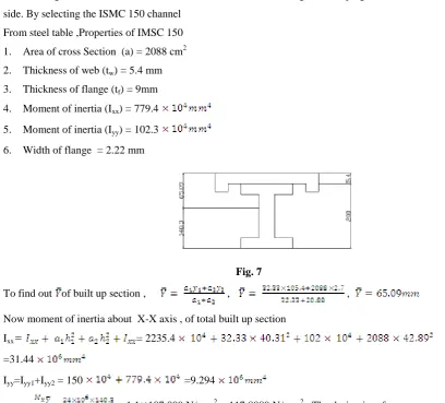
side. By selecting the ISMC 150 channel
From steel table ,Properties of IMSC 150
1. Area of cross Section (a) = 2088 cm2
2. Thickness of web (tw) = 5.4 mm
3. Thickness of flange (tf) = 9mm
4. Moment of inertia (Ixx) = 779.4
5. Moment of inertia (Iyy) = 102.3
6. Width of flange = 2.22 mm
Fig. 7
To find out of built up section , , ,
Now moment of inertia about X-X axis , of total built up section
Ixx = 2235.4
=31.44
Iyy=Iyy1+Iyy2 = 150 =9.294
= = 1.1 107.099 N/mm2 =117.8089 N/mm2. The design is safe
XV. CONCLUSION
By implementing the material handling system shown in Fig.8 we are minimized the cycle time of production
and also reduced the no. of labors from 6 to 2 which indirectly increases productivity as well as profit of the
organization. We are saving 66% manpower required for material handling and saving 89% of cost of material
handling.
247 | P a g e
REFERENCES
Journal Papers
[1]. J.S.Noble, C.m.Kelin&AMidha (November-1998, vol-120), “An inyegrated model of the material handling
system and unit load design problem”
[2]. Yanqiong Zhang, Kai Huang, Weifeng Zhu (2^nd International conference on computer science &
electronics Engg.(ICCSEE2013)) “Model of the equipment selection of material handling system for large ship”
[3]. B.S.Manda and U.S.Palekar (NOV-97, Vol-119) “75th Anniversary issue of the journal of manufacturing
science and engineering.”
[4]. Clifford J.Weinpel,(march-1992)‟ “Material handling system”
BOOKS:
[1]. S. Ramamrutham ,strength of material (DhanpatRai publishing company 17th edition 2011 ) [2]. P S Gill, design data book(DPV Printers edition 1978)
[3]. B.C. Punmia, design of steel structure(Laxmi publication 2nd edition 1998)
[4]. V. B. Bhandari, design of machine element(Tata McGraw hill education Delhi 3rd edition 2010) [5]. R.S. Khurmi J.K. Gupta, machine design(s. chand publication 14th edition 2005)
[6]. Tata steel structure brochure