Published online July 30, 2013 (http://www.sciencepublishinggroup.com/j/acis) doi: 10.11648/j.acis.20130103.17
An analysis of the reciprocal collision avoidance of
cooperative robots
A. Fratu
1, M. Dambrine
2, 3, 4, L. Vermeiren
2, 3, 4, A. Dequidt
2, 3, 41Transilvania University of Brasov, 500036 Brasov, Romania 2Univ. Lille Nord de France, F-59000 Lille, France
3UVHC, LAMIH, F-59313 Valenciennes, France 4CNRS, UMR 8530, F-59313 Valenciennes, France
Email address:
[email protected](A. Fratu), [email protected](M. Dambrine),
[email protected](L. Vermeiren), [email protected](A. Dequidt)
To cite this article:
A. Fratu, M. Dambrine, L. Vermeiren, A. Dequidt, An Analysis of the Reciprocal Collision Avoidance of Cooperative Robots. Automation, Control and Intelligent Systems. Vol. 1, No. 3, 2013, pp. 75-84. doi: 10.11648/j.acis.20130103.17
Abstract:
This paper presents a formal approach that addresses the reciprocal robots collision avoidance, where two robots need to avoid collisions with each other, while moving in a common workspace. Based on our formulation, each physical robot acts fully independently, communicating with the corresponding virtual prototype and imitating its behavior. Each physical robot reproduces the pathway of its virtual prototype. With a view to collision avoidance, it is necessary to detect a possible collision. This action includes the potentially intersecting regions test of the corresponding virtual prototypes. The estimation of the collision-free actions on the virtual robots and the collaborative work of the physical robots which imitate their virtual prototypes are the original ideas. Based on potentially intersecting regions of the virtual robots, we identified a collision-free motion corridor for two cooperative robots. Using the definition of velocity obstacles, we derived sufficient conditions for the collision-free motion of the two virtual robots. We tested the present approach on several complex simulation scenarios involving two virtual robots and estimating collision-free actions for each of them during the cooperative tasks. The focus of this paper is the identification of the collision-free actions for two virtual robots and their behavioral imitation by the physical robots.Keywords:
Virtual Robots, Collision Detection, Reciprocal Collision Avoidance, Behavioral Imitation1. Introduction
Cooperative robots systems are designed to achieve tasks by collaboration. Collaborative robots which we can see deployed nowadays in research or industries are permanently endangered to collide. Therefore, installations with multiple robots in the real world, such as collaborative work and maintenance of the good state of the production line, require collision avoidance methods, which take into account themutual constraints of the robots.
A key requirement for their efficient operation is good coordination and reciprocal collision avoidance.
Collision avoidance is a fundamental problem for cooperative robots. Collision avoidance is a highly advanced robot control option that automatically detects collisions and quickly causes the robot to stop and back up to release the pressure. Not only does it reduces the force of
the collision, but also prevents the robot and its tooling from being pressed against an object after a collision.
The contact of the robot with an obstacle must be detected and it will cause the robot to stop quickly and thereafter back off to reduce forces between the robot and the environment. The problem of the contact with obstacles imposes the null velocity in the moment of the impact.
The problem of the contact detection is better analyzed on the virtual prototypes in the virtual environment, where the virtual objects can be intersected.
The problem of the contact detection in the virtual environment using virtual robots is important for the reason that this built-in function is proven superior to mechanical collision detection devices. It detects collisions in all directions, protecting not only the end-effectors, but also the work pieces and the robot itself.
an environment with obstacles, and /or other moving entities, where the robot employs a continuous acting cycle.
For each cycle, an action for the robot must be computed based on local observations of the environment, so that the robot stays free of collisions with the obstacles and the other moving entities, while making progress towards a goal.
The problem of local collision-avoidance differs from motion planning, where the global environment of the robot is considered to be known and a complete pathway towards a goal configuration is planned at once. Therefore, the collision detection simply determines if two geometric objects are intersecting or not.
The intersecting ormutually penetrating of two objects is possible in the virtual world, where the intersecting of virtual objects is possible, and where there is no risk of destruction.
The ability of predicting the behavior of cooperative manipulators is important for several reasons: for example in design, designers want to know whether the manipulator will be able to perform a certain typical task in a given time frame; in creating feedback control schemes, where stability is a major problem, the control engineer cannot risk a valuable piece of equipment by exposing it to untested control strategies. Therefore, a facile strategy for collision avoidance, capable of predicting the behavior of a robotic manipulator or of the system at whole becomes imperative.
In the real world, like collision detection, where robots need to interact with their surrounding, it is important that the computer can simulate the interactions of the cooperative participants with the passive or active changing environment, using virtual prototyping.
In this paper, we address the more necessary but less studied problem of two-robot reciprocal collision avoidance, where collisions need to be avoided for multiple tasks.
This problem has important applications in many areas in robotics, such as multi-robot cooperation and coordination. It is also a key component in modeling and behavioral simulation of robots, for computer graphics and Virtual Reality.
In this paper, we propose a new method that simultaneously determines actions for two virtual robots that each may have different objectives or will cooperate for a common objective. The actions are computed for each virtual robot and are transferred to the corresponding physical robot, with a central coordination for the collaborative tasks. Yet, we prove that our method guarantees the collision-free motion for each of the robots.
We assume that each virtual robot end-effectors can move in any direction, such that the control input of each robot is given by a three-dimensional velocity vector. Also, we assume that the algorithm is able to deduce the exact shape, position and velocity of obstacles and of the virtual robots, in the virtual environment.
The present simulation method is based on the velocity approach, which provides a sufficient condition for each robot to be collision-free for at least a fixed amount of time into the future. That implies that each robot takes into account the observed velocity of other robots in order to avoid collisions with them. Also, each robot selects its own velocity from its velocity space in which certain regions are marked as “forbidden” because of the presence of another robot.
The formulation “reciprocal collision avoidance”, supposes for each robot that there are a lot of velocities, within the velocity-space, which may to be selected in order to guarantee the collision avoidance.
In this paper we develop and formal analysis of a new collision avoidance strategy for a group of two cooperative robots.
The remainder of this paper is organized as follows: in Section 2, we review prior work in collision avoidance. Section 3 describes collision detection of the virtual objects.
The model we used for reciprocal collision avoidance is described in Section 4. Collision detection through the animation of the virtual robots is detailed in Section 5. A possible strategy of the programming pathway of physical robots, based on a patent is proposed in Section 6. Finally, in Section 7, we present an experimental configuration for physical robot programming by imitation of the virtual prototype and we discuss the limitations and possible extensions of our model to answer complex situations, before concluding.
2. State-of-the-Art and Possible
Extensions
The problem of collision avoidance has been extensively studied. Many approaches assume the observed obstacles to be static (i.e. non-moving), and compute an immediate action for the robot that would avert collisions with the obstacle, in many cases taking into account the robot’s kinematics and dynamics.
If the obstacles are also moving, such approaches typically repeatedly “plan again” based on new readings of the positions of the obstacles. This may work well if the obstacles move more slowly than the robot, but among fast obstacles, the velocity of the obstacles needs to be specified. The problem of the obstacles moving at high speeds is generally referred to as “asteroid avoidance”, and approaches typically extrapolate the observed velocities in order to estimate the future positions of obstacles [10].
Velocity Obstacles (VO) [1, 3, 19] have been a successful velocity-based approach to avoid collisions with moving obstacles; they provide a sufficient and necessary condition for a robot to select velocity that avoids collisions with an obstacle moving at a known velocity.
Besides the Velocity Obstacle approach, many other methods have been proposed for collision-avoidance, navigation, and planning among moving obstacles [12, 13, 18, 19]. There are also Recursive Velocity Obstacles [10] and Common Velocity Obstacle methods [15, 18].
However, most of the existing work does not take into account that the obstacles’ motion may be affected by the presence of the robot. Such approaches are generally not able to plan safe paths among obstacles moving at high speeds [11].
There is also an extensive amount of literature on multi agent navigation, in which each agent navigates individually among the other agents, which are considered as obstacles, e.g. [3, 4, 9 - 16, 18, 19]. Most of these techniques have focused on multitude simulation. Also, in these cases, the other agents are assumed to be either passively moving obstacles or static obstacles. A number of approaches follow the Velocity Obstacle concept to avoid the collision between agents.
In multi-agent planning, the composite configuration space of the agents is considered, and a path is centrally planned in this space [17, 20]. These works focus on different aspects of the problem (e.g. finding optimal coordination) and are frequently not suited for on-line real-time application.
The problem of collision avoidance becomes harder when the obstacles are also intelligent decision-making entities that try to avoid collisions as well. The reactive nature of the other entities must be specifically taken into account in order to guarantee that collisions are avoided.
However, the robot may not be able to communicate with other entities and may not know their intents. It is the case of the Reciprocal Velocity Obstacles (RVO) problem [10, 11], in which robots are partially given the responsibility of avoiding the collisions. This formulation only guarantees collision-avoidance under specific conditions, and does not provide a sufficient condition for collision-avoidance in general.
To overcome this limitation, there exists the Optimal Reciprocal collision Avoidance (ORCA) [15], which provides a sufficient condition for multiple robots to avoid collisions with one another, and thus can guarantee the collision-free operating. However, decoupled multi-agent operation is not only computationally impractical; it also requires central coordination among robots.
Many approaches that in fact guarantee collision avoidance have so far been limited to robots with specific and simple dynamics.
In this paper, we propose a new strategy, which is supposed to detect the collision using the virtual prototypes and to transfer the trajectory of virtual robots to physical
robots, in the real environment, assuming that each physical robot can perfectly imitate the movement /behavior of its virtual prototype.
3. Collision Detection
Collision detection frequently arises in various applications including virtual prototyping, dynamic simulation, interaction and motion planning. Collision detection has been exhaustively researched for more than four decades. Most of the commonly used algorithms are based on spatial partitioning or Bounding Volume Hierarchies (BVHs).
Typically, for a simulated environment consisting of multiple moving virtual objects, collision problems consist of two phases: the “broad phase”, where collision is performed to reduce the number of pair intelligent tests, and the “narrow phase”, where the pairs of objects in proximity are checked for collision.
In this section, we present a study based on the collision detection algorithm for computing all the contacts between multiple moving virtual objects in a large virtual environment. It uses the visibility reducing algorithm described in [2]. The overall algorithm is general and applicable to all environments.
Algorithms for narrow phase can be further subdivided into efficient algorithms for convex objects and general purpose algorithms based on spatial partitioning and BVHs, for polygonal models [2]. However, these algorithms often involve pre-computation and are mainly designed for rigid models.
The performance of collision detection depends on the input model complexity and the problem output, which is the number of colliding or overlapping primitives. However, existing algorithms may not achieve interactive performance on large models consisting of thousands of triangles, due to their high complexity and output of the problem. Moreover, the memory requirements of these algorithms are typically very high.
Based on our strategy, we compute a Potentially Colliding Set (PCS) of virtual objects that are either overlapping or are in close proximity [2].
If an object Oidoes not belong to the PCS, it implies that
Oidoes not collide with any object in the PCS. Based on
this property, we can reduce the number of virtual object pairs that need to be checked for exact collision.
This is similar to the concept of computing the potentially visible set (PVS) of primitives from a viewpoint for spatial relation. We perform visibility computations between the objects in the image space to check whether they are potentially colliding or not.
The object O is considered fully-visible if all the fragments generated by the rasterizing of O have a depth value less than the corresponding pixels in the frame buffer. We do not consider the self masking of a virtual object O in checking its visibility status.
If an object does not intersect in either of the two passes, then it does not belong to the PCS. Each pass requires the object representation for an object to be rendered twice. We can either render all the triangles used to represent an object or a bounding box of the object. Initially, the PCS consists of all the objects in the scene.
We perform these two passes to reduce objects from the PCS. We will check if an object potentially intersects with a set of objects or not.
It should be noted that our method based on reducing algorithm [7] is quite different from algorithms that reduce PCS using 2D overlap tests.
Many applications need to compute the exact overlapping features (e.g. triangles) for collision response. Instead of testing each object pair in the PCS for exact overlap, we again use the visibility formulation to identify the potentially intersecting virtual regions among the objects in the PCS.
Specifically, we use a fast global reducing algorithm to localize these regions of interest. We perform object level reducing to compute the PCS of objects.
Initially, all the objects belong to the PCS. Firstly, we perform the reduction along each coordinate axis by using the axis aligned bounding boxes as the object’s representation for collision detection. The reduction is performed till the PCS does not change between successive iterations.
We also use the object’s triangulated representation for further reducing the PCS.
The size of the resulting set is expected to be small and we use all-pair bounding box overlap tests to compute the potentially intersecting pairs.
If the size of this set is large, then we use the sweep-and- reduce technique [5] to reduce this set instead of performing all-pair tests.
We decompose each object into sub-objects. We have extended this approach at sub-object level and computed the potentially intersecting areas.
4. Reciprocal Collision Avoidance
For two robot end-effectors A and B, the velocity obstacle,
τ
B A
VO
(read: the velocity obstacle for A induced by B fortime window τ ) is the set of all relativevelocities of A with respect to B, which will result in a collision between A and B at some moment before time τ [9]. It is formally defined as follows.
Let be an A robot end-effector with radius rA, positioned
at pA on a horizontal disc. For a configuration of two robot
end-effectors A and B, the horizontal disc of radius (rA+ rB)
iscentered at (pB− pA) in the Cartesian space.
Let S (p, r) denote an open horizontal disc of radius r centered at vector position p and defined by (1).
}
,
{
)
,
(
r
S
r
S
p
=
s
∈
s
−
p
≤
(1)Then the velocity obstacle is defined as:
)}
,
(
],
,
0
[
{
B A A BB
A
v
t
vt
S
r
r
VO
τ=
∃
∈
τ
∈
p
−
p
+
(2)Let vtAand vtBbe the current operational velocities of the
robots’ end-effectors A and B, respectively. The definition of the velocity obstacle implies that if (vA - vB)
є
VO
τAB, orequivalently if (vB -vA)
є
VO
τBA, then A and B will collideat some moment before time τ if they continue moving at their current velocity.
On the other hand, if (vA-vB)
¢
VO
τAB, the two robotend-effectors A and B are guaranteed to be collision-free for at least τ time. Robot end-effector A will collide with robot end-effector B within τ time if its velocity vA is inside
τ B A
VO
and it will be collision-free for at least τ time if its velocity is outside the velocity obstacle.For an articulated robot arm, the robot end-effectors velocity vector is calculated as, v= XɺtwhereXt is the
Cartesian position vector of the robot end-effector. The vector Xt can be described as a function of robot joints
variables vector, q:
)
f(
q
=
t
X (3)
Equation (3) can be obtained easily with the help of the Denawit - Hartenberg operators.
The robot end-effectors velocity vector vcan be obtained as:
q
q
J
ɺ
ɺt t(
)
X
v
=
=
(4)where J is a Jacobean matrix, and
q
ɺ
is the robot joints velocities vector.Given a trajectory that each moving robot end-effector will travel, we can determine the exact collision time. Please refer to [18] for more details. If the path that each robot end-effector travels is not known in advance, then we can calculate a lower bound on the collision time. This lower bound on the collision time is calculated adaptively to speed up the performance of the dynamic collision detection.
5. Collision Detection through
Animation of two Virtual Robots
object pairs from a stack according to their approximate time of collision, as the objects move in a dynamic environment.
Our simulation method purely exploits the spatial arrangement of the two end-effectors without any other information.
The end-effector pair which has a small separation is likely to have an impact within the next few time instances, and those virtual pairs which are far apart from each other cannot possibly come to interfere with each other until a certain moment.
For spatial tests to reduce the number of virtual pairs judicious comparisons, we assume the environment is quite free and the end-effectors move in such a way that the geometric coherence can be preserved, i.e. the assumption that the motion is essentially continuous in the time domain.
Planning scene formulation for cooperative tasks is presented in the figures below.
In the cooperative task studies, the simulation is used to find whether it is possible to avoid the collision between a particular part of the robot arm and diverse objects in the work space and so to find one possible free path.
In this section we will describe how to render a planning scenario in the form of constraints for the constraint-based planning framework.
Our visibility using the PCS computation algorithm is based on a hardware visibility query which determines if a primitive is fully-visibleor not.
By assuming that the geometry representing the robots and obstacles is given, the motion is prescribed for obstacles over time.
Our system then defines constraints that will restrict the motion of the robots to meet the design specifications, and also guides the robots to complete the planning tasks so that the collision will be avoided.
Our virtual system was implemented on a programming platform, using the Delphi object-oriented programming language.
In this section we have tested our system of two robots for collision detection in the following scenes for the virtual prototyping applications.
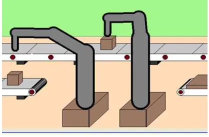
5.1. Scene 1: Individual Task for each Robot
The individual task for each robot is studied in scene 1. Each of the two robot arms is composed of rigid components that are held together by constraints. For all of the components of the robot arm, the planner must compute paths to ensure the joint constraints do not collide with the obstacles as the conveyors and lead the end-effectors along the prescribed path.
In this scene (an example seen in Fig. 1), two articulated robot arms, with six degrees of freedom, are used to transfer (manipulate) cubic objects from one conveyor belt to another conveyor belt.
Each robot arm follows a path over the conveyor body while avoiding obstacles.
Figure1.Scene for individual tasks
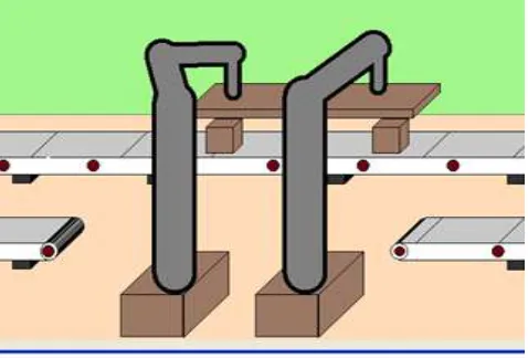
5.2. Scene 2: Cooperative Mission
The cooperative mission for two robots is analyzed below. In our example, a second scene shown in Fig. 2, the end-effectors of the left robot and of the right robot respectively, avoid each other in a firm behavior during a cooperative task. In this scene, two articulated robot arms, with 6 degrees of freedom, are used to manipulate together a rigid object for an assembly operation. The robot arms avoid the moving belt to get in touch with a plate object passing it on the assembly conveyer belt. The goal to manipulate together the same object in a cooperative mission requires both robots to maneuver around each other without colliding.
Figure 2.Scene for cooperative mission
5.3. Scene 3: Assembly Line Planning
In this example, shown in Fig. 3, two robot arms must assemble a plate object with two cubical objects, on a conveyer belt.Both robots must be moved simultaneously around each other to position the plate object on top of the two cubical objects and to avoid collision. The assembly line contains a support structure that is moving over the conveyer belt in the same direction as the assembled parts.
of the graphics processing units, it may not be possible to visualize or perform collision detection between massive models at interactive rates on graphics hardware.
Figure 3.Scene for assembly line planning
Since the usual models of the cooperative robots are rather complex and may have thousands of components, the algorithm as described in [10, 11], becomes essential to generate a realism of motion.
The visual results indicate that the approximated implicit integration, mixed with the post-step inverse dynamics process, achieves simulation of rigid objects very well.
6. Possible Strategy of the Programming
Pathway of the Physical Robots
We propose an original idea that allows us to transfer the joint trajectory of each virtual robot to the corresponding joint of the real (physical) robot. With other worlds we prepare the free-trajectories for the pair of the virtual cooperative robots; these trajectories can be transferred to their corresponding pair of the physical cooperative robots.
In the real world, the programming pathway of the physical robots can be realized using the pathway of the virtual robot prototypes [9]. Therefore, the virtual robot behavior must be specifically taken into account in order to guarantee that collisions are avoided between corresponding physical robots. Each real robot may be able to communicate with her virtual corresponding entity and may imitate their intents. We call this problem reciprocal collision avoidance using the virtual robots prototypes, and it is the focus of this paper.
The strategy that we realized in this paper, for the virtual robots, is formally defined as follows. Let there be a set of two virtual partners-robots sharing a virtual environment. Each robot has a current position and a current velocity. These parameters are part of the robot’s external state, i.e. we assume that they can be estimate in the virtual environment.
Furthermore, each virtual robot has a maximum speed and a preferred velocity, which is the velocity the robot
would assume had no other robot/object been in its way. We consider these parameters part of the internal state of the robot, and can therefore not be observed by the other robot.
The task is for each virtual robot to independently(and simultaneously) select a new velocity for itself such that bothvirtual robots are guaranteedto be collision-free for at least a fixed amount of time, when they would continue to move at their new velocity.
As a secondary objective, the virtual robots should select their new velocity as close as possible to their preferred velocity. The virtual robots are not allowed to communicate with each other, and can only use observations of the partner-robot’s current position and velocity.
In our collaborative work systems, the virtual robot prototypes are used mainly as an intermediate result for calculating the “nearest neighbors” and the potentially intersecting areas in a possible collision. We compute a PCS of virtual objects that are either partly covered or in close proximity. If an object does not belong to the PCS, it implies that this objectdoes not collide with any object. We initially compute the PCS of virtual objects based on the above algorithm (section 3 and 4). As an alternative of testing each object pair in the PCS for partial cover, we use the visibility formulation to identify the potentially intersecting virtual areas among the objects.
Based on this property, we developed a programming platform for a pair real (physical) robots based on a cooperative virtual robot’s pair, which needs to be checked for exact collision detection. This platform needs to compute the exact overlapping area of the virtual cooperative robots, as collision response.
7. Experimental Configuration for
Programming by Imitation of an
Anthropomorphic Robot
A physical anthropomorphic robot is controlled to follow the arbitrary path reference with a predefined velocity profile over time. The physical robot follows an imaginary robot path which is ideally generated by the virtual robot. The physical robot must follow the virtual robot’s trajectory.
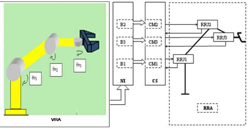
On the basis of robot kinematics equations, a robot control system is presented in Fig. 4.
Fig. 4 also displays (left image) the user interface for a virtual anthropomorphic robot arm, which has been created by the motion simulation system.
joint angles data from a motion capture system to the kinematic model for an anthropomorphic robot.
To generate the desired motion sequence for the real robot, we capture the motions from a virtual robot model and map these to the joint settings of the physical robot.
Initially, a set of virtual postures is created to the virtual robot arm, VRA and the pictures’ positions are recorded for each posture, during motion [9].
These recorded pictures’ positions provide a set of Cartesian points in the 3D capture volume for each posture.
To obtain the final robot posture, the virtual pictures’ positions are assigned as positional constraints on the physical robot. To derive the joint angles, standard inverse kinematics (IK) routines are used.
The IK routine then directly generates the desired joint angles on the robot for each posture.
We assume the use the virtual robot prototypes and the motion capture systems to obtain the reference motion data, which typically consist of a set of trajectories in the Cartesian space.
The data is obtained using a motion capture channel taking into account the joint motion range. The symbolic spatial relations specifying the virtual environment can be used for the automatic planning of the possible virtual path as reference for the real robotic arm, RRA, which may guide the motion process during execution.
Figure 4.Programming platform with the corresponding virtual robot and the real robot face-to-face
The easiest way to generate the spatial relations explicitly is the interactively programming of the behavior of the vir-tual prototype in its virvir-tual environment in order to specify suitable position coordinates θv1, θv2, θv3. These position
coordinates are used by the physical robot as reference po-sition coordinates.
This kind of specification provides an easy to use interactive graphical tool to define any kind of robot path; the user has to deal only with a limited and manageable amount of spatial information in a very comfortable manner.
An automatic robot programming system has to recognize the correct robot task type and should map it to a sequence of robot operations [6]. The desired pathways are automatically transferred and parameterized in the NI, using the path planner. The physical robot receives the position coordinates of the virtual robot through NI.
Fig. 4 shows a simple path-following system which keeps a constant communication between the virtual robot’s path and the control system, CS. The control system is designed to force the real robot to follow the reference path.
The main program simply defines “start” and “goal” positions. After moving the virtual robot to the ‘start’
position in the joint “interpolation” mode, the real robot is moved in the “following” mode, while a “monitor function” has been activated.
The “monitor function” is reading the reference path values, which are used in closed loops to compute the physical joint torques.
In similar ways, any functional dependencies of some path properties (speed, distance etc.) can be specified in a textual programming manner.
The trajectories are sent to visualization, so that users can see the results of the animation.
The robot’s control system is connected via the Transmission Control Protocol (TCP) to a PC, equipped with the interface card; the PC is running the simulation and control process. The robot control system receives and executes each 16 ms, an elementary move operation.
unit ControlCAN;
interface
uses
WinTypes;
const
DLL_NAME = 'ControlCAN.dll';
type
//1.ZLGCAN
VCI_BOARD_INFO = Record
hw_Version : WORD;
fw_Version : WORD;
dr_Version : WORD;
in_Version : WORD;
irq_Num : WORD;
can_Num : BYTE;
str_Serial_Num : array[0..19] of CHAR;
str_hw_Type : array[0..39] of CHAR;
Reserved : array[0..3] of WORD;
END;
PVCI_BOARD_INFO=^VCI_BOARD_INFO;
//2.
VCI_CAN_OBJ = Record
ID : UINT;
TimeStamp : UINT;
TimeFlag : BYTE;
SendType : BYTE;
RemoteFlag : BYTE;
ExternFlag : BYTE;
DataLen : BYTE;
Data : array[0..7] of BYTE;
Reserved : array[0..2] of BYTE;
END;
PVCI_CAN_OBJ = ^VCI_CAN_OBJ;
//3.
VCI_CAN_STATUS = Record
ErrInterrupt : UCHAR;
regMode : UCHAR;
regStatus : UCHAR;
regALCapture : UCHAR;
regECCapture : UCHAR;
regEWLimit : UCHAR;
regRECounter : UCHAR;
regTECounter : UCHAR;
Reserved : DWORD;
END;
PVCI_CAN_STATUS = ^VCI_CAN_STATUS;
//4.
VCI_ERR_INFO = Record
ErrCode : UINT;
Passive_ErrData : array[0..2] of BYTE;
ArLost_ErrData : BYTE;
END;
PVCI_ERR_INFO = ^VCI_ERR_INFO;
//5.
VCI_INIT_CONFIG = Record
AccCode : DWORD;
AccMask : DWORD;
Reserved : DWORD;
Filter : UCHAR;
Timing0 : UCHAR;
Timing1 : UCHAR;
Mode : UCHAR;
END;
PVCI_INIT_CONFIG = ^VCI_INIT_CONFIG;
//6.
function VCI_OpenDevice ( DeviceType : DWORD;
DeviceInd : DWORD;
Reserved : DWORD) : DWORD;
stdcall;
external DLL_NAME;
function VCI_CloseDevice ( DeviceType : DWORD;
DeviceInd : DWORD) : DWORD;
stdcall;
external DLL_NAME;
function VCI_InitCAN ( DeviceType : DWORD;
The applicable robot tasks are designed and the desired pathways are programmed off-line and stored in the buffers B1, B2, B3.
The following errors are delivered by the comparative modules CM1, CM2, CM3. The controllers interpret fol-lowing errors and generate corresponding variables, which are transmitted to the actuators.
Process changes from disturbances result in new sensor signals, identifying the state of the process, to be transmit-ted again to the controller. A control loop, including sensors, control algorithms and actuators, is arranged for each joint in such a way as to try to regulate the position variables at reference positions value to obtain the desired closed loop performances.
While motion execution is in progress, the real robot joints RRJ1, RRJ2, RRJ3 are activated into the real environment. Each time, a skill primitive is executed by the CS; it changes the robot joints state. As no time limit for the motion is specified, the real robot imitates the behavior of the virtual robot.
In our experimental configuration, in order to prove the correctness of the robot programming by imitation, we have chosen an anthropomorphic robot arm, with 3 DOF equipped with electrical actuators, mounted on the real robot’s joints.
The designed control algorithm proved stable and robust to the errors when following the reference path, to input and output noises and to other disturbances.
8. Conclusion and Future Work
This paper gives an application of the collision detection algorithm described in [2, 10, 11], for virtual manipulation planning with virtual robots. We have applied this algorithm to perform collision detection in a virtual environment.
This algorithm has also been utilized for dynamic simulation and its practicality has been demonstrated for different applications.
The distance computation method, described in [11] has been used in the dynamics simulator written in the Delphi language.
Our vision of this dynamic simulator is the ability to simulate small mechanical parts of a robot arm. It reduces the frequency of the checks significantly, so as to help speed up the calculations.
We revealed the potential of the Reciprocal Velocity Obstacle approach by applying it to scenarios in which two virtual robots accomplish their tasks, independently or in cooperation, in a complex environment.
We would like to extend the current method, allowing it to handle various types of time-varying data sets used in animation process.
Furthermore, we would like to apply our collision detection framework to several applications including the motion planning of physical robotswhile passing near each other.
In our formulation, the real robots must have exactly the same dynamics model as virtual robots in order to be able to imitate the behavior of the latter.
Virtual robots could be handled using an abstraction of the dynamics model of their real homologue. Real robots will imitate the virtual robot's behavior and will move according to it.
For virtual robots, we have implemented this algorithm in 2D and 3D. In 3D, we used an immersive environment, to be able to virtually manipulate the animated objects. We ordered the robots to grip the object and move it around a scene containing different obstacles situated on a ground plane.
It is important to note here that this virtual model is not dynamic, but rather a succession of static postures, which greatly limits its applications. We experimented with our approach on several complex simulation scenarios, containing virtual interoperations. As each robot is
independent, we can fully parallelizethe simulation of the actions for each robot to realize the animation.
Actually, the method and installation described in [9] are currently under testing to be eventually integrated into a real collision environment, developed at Transilvania University of Brasov.
In addition to discussing the original contributions, this paper presents a set of directions to be considered for future work.
The authors intend to extend experiments to investigate these ideas and examine the possibility of how to implement them.
The authors expect fully automated robot programming by imitation based on this method, using robust enough system to be applied in industrial applications, will not be-come true before the end of this decade.
Acknowledgements
The authors wish to thank the entire team at LAMIH Laboratory of University of Valenciennes-France, for cooperation and engagement in the research activity in the field of robotics.
This cooperation gave us the opportunities to work in a multidisciplinary team and provided us important experiences to extend our research in future projects.
References
[1] C. Fulgenzi, A. Spalanzani, C. Laugier, “Dynamic obstacle avoidance in uncertain environment combining PVOs and occupancy grid”. In Proc. IEEE Int. Conf. on Robotics and Automation, pp.1610–1616, 2007.
[2] N. K. Govindaraju, S. Redon, M. C. Lin and D. Manocha, “CULLIDE: Interactive Collision Detection Between Complex Models in Large Environments using Graphics Hardware”, M. Doggett, W. Heidrich, W. Mark, A. Schilling (Editors), Graphics Hardware, 2003.
[3] D. Hennes, D. Claes, W. Meeussen, K. Tuyls, “Multi-robot collision avoidance with localization uncertainty”, In: Proceedings of the 11th International Conference on Autonomous Agents and Multiagent Systems, Conitzer, Winikoff, Padgham, and van der Hoek (eds.), June, 4– 8, 2012, Valencia, Spain.
[4] Y. Abe, M.Yoshiki, “Collision avoidance method for multiple autonomous mobile agents by implicit cooperation”. IEEE/ RSJ, Int. Conf. Intelligent Robots and Systems, pp.1207-1212, 2001.
[5] K. O. Arras, J. Persson, N. Tomatis, R. Siegwart, “ Real-Time Obstacle Avoidance for Polygonal Robots With a Reduced Dynamic Window” in Proc. IEEE Int. Conf. on Robotics and Automation, Washington DC, May 2002, pp.3050-3055.
faculty of the University of North Carolina Chapel Hill, 2008.
[7] S.E. Yoon, “Interactive Visualization and Collision Detection using Dynamic Simplification and Cache-Coherent Layouts”. Dissertation submitted to the faculty of the University of North Carolina, Chapel Hill, 2006.
[8] A. Fratu, L. Vermeiren, A., Dequidt, “Using the Redundant Inverse Kinematics System for Collision Avoidance. The 3rd International Symposium on Electrical and Electronics Engineering - ISEEE- 2010, 16-18 sept. Galati, Romania, Proceedings ISBN 978-1- 4244-8407-2, pp. 88-93.
[9] A. Fratu, “Method and installation for joints trajectory planning of a physical robot arm” (proposal - patent) unpublished.
[10] J. van den Berg, S. Guy, M. Lin, D. Manocha, “ Reciprocal n-body collision avoidance”. In: Proc. Int. Symposium on Robotics Research, 2009
[11] J. van den Berg, S. J. Guy, M. Lin, and D. Manocha, C. Pradalier, R. Siegwart, and G. Hirzinger, ”Reciprocal n-body collision avoidance”, Robotics Research, The 14th International Symposium ISRR, Springer Tracts in Advanced Robotics, vol. 70, Springer-Verlag, May 2011, pp. 3-19.
[12] J. Snape, J. van den Berg, S. J. Guy, and D. Manocha, “Independent navigation of multiple mobile robots with hybrid reciprocal velocity obstacles”, IEEE/RSJ Int. Conf. Intelligent Robots and Systems, St. Louis, Mo., 2009.
[13] J. Snape, S. J. Guy, J. van den Berg, S. Curtis, S. Patil, M. Lin, and D. Manocha, “Independent navigation of multiple robots and virtual agents”. In Proc. of the 9th Int. Conf. on Autonomous Agents and Multi agents Systems (AAMAS 2010), Toronto, Canada, May 2010.
[14] S. J. Guy, J. Chhugani, C. Kim, N. Satish, M. Lin, D. Manocha, and P. Dubey, “ Clear Path: Highly Parallel Collision Avoidance for Multi-Agent Simulation” In: Proc. ACM SIGGRAPH/Eurographics Symposium on Computer Animation (SCA), Aug. 2009.
[15] J. Snape, J.van den Berg, S.J. Guy, D. Manocha, “S-ORCA: Guaranteeing Smooth and Collision-Free Multi-Robot Navigation Under Differential-Drive Constraints”. In: Proc. IEEE Int. Conf. Robotics and Automation, 2010.
[16] D. M. Stipanovic, P. F. Hokayem, M. W. Spong, D. D. Siljak, “Cooperative Avoidance Control for Multiagent Systems”. In: ASME Journal of Dynamic Systems Measurement and Control, Vol.129, pp. 699–707, 2007.
[17] R. Diankov and J. Kuffner, “Openrave: A planning architecture for autonomous robotics”. Technical report, CMU-RI-TR-08-34, The Robotics Institute, Carnegie Mellon University, 2008.
[18] M. Turpin, N. Michael, V. Kumar,” Trajectory planning and assignment in multi robot systems”. Proc. Workshop on Algorithmic Foundations of Robotics, 2012.
[19] J. van den Berg, D. Wilkie, S. Guy, M. Niethammer, D. Manocha, “LQG-Obstacles: Feedback control with collision avoidance for mobile robots with motion and sensing un-certainty.” IEEE Int. Conf. on Robotics and Automation, River Centre, Saint Paul, Minnesota, USA, May 14-18, 2012, pp. 346- 353.