Communication
1
Bottom-Up Synthesis of Porous NiMo Alloy for
2
Hydrogen Evolution Reaction
3
Kailong Hu 1, Samuel Jeong 1, Mitsuru Wakisaka 2,3, Jun-ichi Fujita 1 and Yoshikazu Ito 1,2,*
4
1 Institute of Applied Physics, Graduate School of Pure and Applied Sciences, University of Tsukuba,
5
Tsukuba, Ibaraki 305-8573, Japan
6
2 PRESTO, Japan Science and Technology Agency, Saitama 332-0012, Japan
7
3 Graduate School of Engineering, Toyama Prefectural University, 5180 Kurokawa, Imizu,
8
Toyama 939-0398, Japan
9
* Correspondence: [email protected]; Tel.: +81-29-853-5247
10
Abstract: Bottom-up synthesis of porous NiMo alloy reduced by NiMoO4 nanofibers was
11
systematically investigated to fabricate non-noble metal porous electrodes for hydrogen production.
12
The different annealing temperatures of NiMoO4 nanofibers under hydrogen atmosphere reveal
13
that the 950 °C annealing temperature is a key to produce bicontinuous porous NiMo alloy without
14
oxide phases. The porous NiMo alloy as cathodes in electrical water splitting demonstrates not only
15
almost identical catalytic activity with commercial Pt/C in 1.0 M KOH solution, but also superb
16
stability for 12 days at an electrode potential of −200 mV (v.s. RHE).
17
Keywords: nanoporous; NiMo; non-noble metal catalyst; hydrogen evolution
18
19
1. Introduction
20
Nanoporous metals are key materials for energy engineering fields because of outstanding
21
conductivity, bi-continuous open porous structures with tunable porosity, large surface area,
22
excellent catalytic activities and high mechanical strength [1, 2]. Recently, nanoporous non-precious
23
metals has been focused as electrodes and catalysts such as supercapacitor [3, 4], Li-air battery [5, 6],
24
fuel cell and water electrolysis [7, 8], showing great potentials as precious metal-free electrodes. The
25
fabrication process of nanoporous metal employs a dealloying method [1] that the solid solution alloy
26
of precious metal and non-precious metal was electrochemically corroded in acidic electrolytes.
27
However, in this method, the alloy combinations in the dealloying method is very limited and the
28
non-precious metal of Ni, Fe and Cu is usually the one to be removed from the alloy, forming precious
29
metal-based nanoporous structures. Therefore, the desirable design of non-precious metal has been
30
explored to expand their applications.
31
Nanoporous non-precious metal have been synthesized by bottom-up approaches such as
32
nanoparticle-sintering [9, 10] and reduction of metal oxides [11, 12]. Especially, the reduction of metal
33
oxide is a powerful method to prepare nanoporous non-precious metal. One of attractive porous
34
metals is NiMo alloy which is known as one of the best hydrogen evolution electrode catalyst [13, 14]
35
for cost-effective and highly efficient hydrogen production in water electrolysis. Although different
36
kind of NiMo alloy porous morphologies were investigated as HER catalysts including Ni4Mo [15],
37
NiMo nanopowder [16], NiMo nanowire [17], the performances show the HER performance is not
38
very enhanced due to the absence of bi-continuous and monolithic porous structures. Indeed, the Ni
39
foam supported Ni4Mo nanoparticles and the three-dimensional NiMo nanowires significantly
40
improved their HER activities. This means that bi-continuous and monolithic 3D electrode catalysts
41
bring high reaction kinetics. Therefore, NiMo alloy with bicontinuous open porous 3D structure can
42
be a central electrode catalyst for electrical water splitting combined with renewable energy such as
43
wind, water and solar energies to produce eco-friendly hydrogen production without any carbon
44
emission.
45
In this study, we have systematically investigated porous NiMo alloy with different annealing
46
temperatures from 400oC to 950oC to understand the formation of porous structures by reduction
47
under hydrogen atmosphere. Moreover, the electrochemical performances of resulting porous NiMo
48
alloy samples were tested in 1 M KOH electrolyte with the comparison of the best catalyst of platinum
49
(Pt). The durability test in 1 M KOH electrolyte was further carried out by cyclic voltammetry and
50
chronoamperometry measurements.
51
2. Materials and Methods
52
Preparation of NiMoO4 nanofibers. NiMoO4 nanofibers, synthesized by a standard
53
hydrothermal method [18, 19], were used as precursors to obtain 3D porous NiMo alloy through a
54
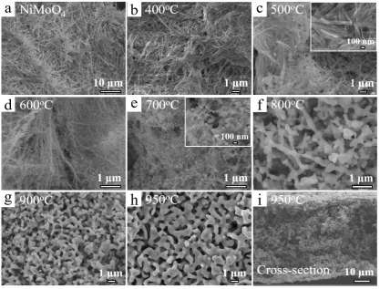
reductive annealing system. 2.5 mmol NiCl2·6H2O (wako, 98% purity) and 2.5 mmol Na2MoO4·2H2O
55
(wako, 99% purity) were dissolved in 30 ml deionized water, and then was transferred into a 50 ml
56
Teflon coated stainless autoclave, which was kept at 150oC for 12 h. After the autoclave cooling down
57
to room temperature, the as-prepared NiMoO4 nanofibers were washed by deionized water several
58
times with a centrifuge, and kept in deionized water.
59
Preparation of porous NiMo alloy. The NiMoO4 nanofiber solution was dropped on Cu sheets,
60
and dried naturally for one day. The dried NiMoO4 (5.0 g) was put into the center of a quartz tube
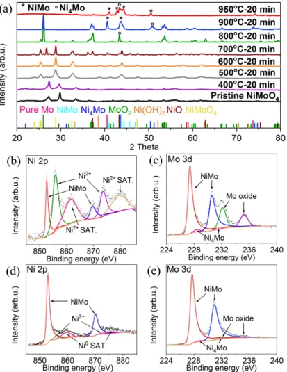
61
(φ30×φ27×1000 mm) furnace. The NiMoO4 was reduced at various temperatures from 400−950oC for
62
20 min under the mixed atmosphere of hydrogen (100 sccm) and argon (200 sccm) to reduce oxides
63
for porous structure formation. After the annealing, the resulting reduced samples were removed
64
from the Cu sheets for measurements.
65
Imaging and spectroscopic characterization. The morphology and microstructure of 3D NiMo
66
alloy were characterized by a scanning electron microscope (SEM, JEOL JSM-4300). The X-ray
67
diffraction (XRD) was carried out using a RIGAKU SmartLab 9MTP diffractometer with a 9.0 kW
68
rotating anode generator (Cu Kα1 radiation; λ = 1.5406 Å). The X-ray photoelectron spectroscopy
69
(XPS, AXIS ultra DLD, Shimazu) with Al Kα and X-ray monochromator was utilized for surface
70
chemical compositions analysis. The surface area of porous NiMo sample was measured by the
71
Brunauer–Emmett–Teller (BET) methods using a BELSORP-mini II (BEL. JAPAN. INC) at 77.0 K. The
72
sample was heated at 120°C under vacuum for 48 hours before the measurements.
73
Electrochemical characterizations. Hydrodynamic voltammetry for HER and electrochemical
74
impedance spectroscopy (EIS) were conducted using an electrochemical workstation (Biologic,
VSP-75
300) equipped with a rotation disk electrode (RDE, 5 mm diameter glassy carbon, HOKUTO DENKO
76
corp.). A graphite plate, an Ag/AgCl electrode (HOKUTO DENKO corp.) and the porous NiMo
77
samples (5 mg) dispersed on the glassy carbon served as the counter electrode, the reference electrode
78
and the working electrode, respectively. The porous NiMo samples and 10wt% Pt/C (Sigma-Ardrich)
79
were dispersed uniformly on the surface of the glassy carbon electrode using Nafion (wako, 5%
80
DE521 CS type) as a binder. The Ag/AgCl electrode was compared with a flesh Ag/AgCl electrode to
81
check the differences of potential before use. All potentials were calculated with respect to RHE using
82
the equation: E(RHE) = E(Ag/AgCl) + 0.0591 × pH + 0.1976. The cyclic voltammetry (CV)
83
measurements after several cycles were recorded from −250 mV to +100 mV (v.s. RHE) at a sweep
84
rate of 10 mV/s in 1 M KOH electrolyte (pH=13.9) deaerated with Ar (99.999%) with disk rotation
85
speed of 1600 rpm to remove generated hydrogen bubbles. The electrode potential in the
86
hydrodynamic voltammogram was automatically iR-compensated with the Ohmic resistance
87
measured at +200 mV (v.s. RHE). The EIS measurement was carried out at −200 mV (v.s. RHE) with
88
an amplitude of 50 mV. The durability of the electrodes was tested by potential cycling between −250
89
mV to +100 mV (v.s. RHE) at 10 mV/s. The electrolyte after 2000 CV cycle test was collected and
90
analyzed through ICP-OES (Thermo Fisher Scientific IRIS Advantage DUO) to determine the
91
leaching amount from NiMo catalyst.
3. Results and Discussion
96
The fabrication process of 3D porous NiMo alloy, illustrated in Figure 1., was divided into two
97
main procedures. Firstly, the NiMoO4 nanofibers, the precursor of porous NiMo, were synthesized
98
through a standard hydrothermal method at 150oC for 12 hours. Secondly, the resulting NiMoO4
99
nanofibers dropped on Cu sheets and inserted into a quartz tube furnace were annealed at 400-950oC
100
for 20 min under the mixed gases of hydrogen and argon to reduce the oxidized precursor. After the
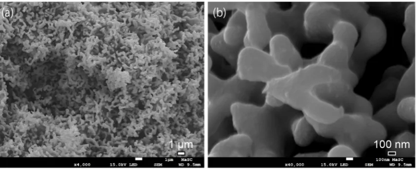
101
furnace cooling down to room temperature, the annealed NiMoO4 samples were peeled off from the
102
Cu sheets for characterizations and measurements. Moreover, the sheet area easily reached to 2 cm2
103
(Figure 1) when the area of Cu sheet was tuned.
104
105
Figure 1. Schematic illustration of the synthesis process of 3D porous NiMo alloy.
106
The morphologies of annealed NiMoO4 samples were investigated to reveal the formation
107
process of porous structures with scanning electron microscope (SEM) measurements. The nanofiber
108
structure was kept at low temperatures of 0-500oC (Figure 2a-c), and some nanoparticles were
109
generated on the surface of nanofibers at 500oC due to the reduction of NiMoO4 nanofibers (inset of
110
Figure 2c). When the temperature reached to 600oC, the generated nanoparticles started to fuse and
111
reconstruct each other to be energetically stable due to the high geometric potential at the
112
nanoparticle state (Figure 2d). The pristine nanofiber structures were totally disappeared at 700oC
113
and the ligaments in the porous structures were gradually formed with pore size less than 100 nm
114
(Figure 2e). The 3D open porous structures were developed and the porous structures became
115
bicontinuous and interconnected above 800oC (Figure 2f). The porous structures were well developed
116
and the pore size increased from tens of nanometers to a few hundred nanometers with the
117
temperature ranging from 800 to 950oC (Figure 2g-h). The view of cross-section of sample annealed
118
at 950oC showed the open and bicontinuous structures were well preserved in the inside of sample
119
sheets (Figure 2i).
120
The crystal structures of annealed NiMoO4 samples were studied by X-ray diffraction (XRD)
121
measurements (Figure 3a). The pristine NiMoO4 nanofibers and sample annealed at 400oC matched
122
well with the NiMoO4∙xH2O (JCPDS #13-0128) (Figure S1). When the annealing temperature ranges
123
between 500-600oC, the obtained peaks were well assigned to NiMoO4 (JCPDS #33-0948). This can be
124
explained with the complete removal of crystalline water at 500-600oC. At 700oC, some NiMoO4 were
125
reduced and decomposed under the reductive atmosphere, partly forming NiO (JCPDS #71-1179)
and MoO2 (JCPDS #65-5787). Above 800oC, the composition of NiMo (JCPDS #48-1745), Ni4Mo
127
(JCPDS #65-5480), and pure Mo (JCPDS #42-1120) were gradually generated and oxidized species of
128
NiO and MoO2 were gradually reduced. The Ni(OH)2 (JCPDS #14-0117) was created from pure Ni
129
when it exposed into air for XRD measurements. It is worthy noted that the reduction of NiMoO4
130
requires 800oC and reduction of MoO2 requires 950oC. Thus, the sample annealed at 950oC only
131
obtains NiMo with certain amount of Ni4Mo alloys. In addition, the high resolution XRD patterns of
132
samples annealed at 800oC, 900oC and 950oC are displayed in Figure S2. The specific surface area of
133
the porous NiMo annealed at 950oC was measured by the BET methods. The surface area was
134
estimated as 2.81 m2/g (Figure S3).
135
136
Figure 2. SEM images of (a) pristine NiMoO4 nanofiber; (b-i) temperature effect of 3D porous structure
137
formation on samples annealed at 400oC-950oC. The insets in (c) and (e) show high resolution SEM images.
138
The surface chemical compositions of porous NiMo and Ni4Mo alloy samples annealed at 900oC
139
and 950oC were tested by X-ray photoelectron spectroscopy (XPS) measurements. The
high-140
resolution Ni 2p spectrum of the sample annealed at 900oC reveals that the main peaks are assigned
141
to Ni (852.6 eV, 869.6 eV) and NiO (855.9 eV, 873.6 eV), while the NiO peaks of the sample annealed
142
at 950oC are negligibly small (Figure 3b, 3d) [20-22]. These results further indicate that Ni oxides were
143
completely reduced at 950oC. The high-resolution Mo 3d spectrum of samples annealed at 900oC were
144
deconvoluted into six distinct peaks at 227.4 eV, 230.6 eV, 228.5 eV, 231.6 eV, 232.1 eV and 235.2 eV,
145
assigning to NiMo, Ni4Mo and Mo oxide, showing alloy and oxidized surface state (Figure 3c)
[23-146
25]. The sample annealed at 950oC presents major NiMo (94.4 at%) with negligible Ni4Mo (1.5 at%)
147
and Mo oxide on the surface, further confirming the almost complete reduction of Mo oxide (4.1 at%,
148
probably oxidized during the transfer to XPS measurements) at 950oC (Figure 3e). These XPS results
149
are good agreements with the XRD results. Considering XRD and XPS results during the reduction
150
process, the following sequential transformations are proposed: (1) the reduction of pristine NiMoO4
151
to partly-reduced NiMoO4 nanoparticles, (2) the reconstruction and fusion of the further-reduced
152
NiMoO4 nanoparticles to decrease the surface energy and (3) the complete reduction of NiMoO4
nanoparticles for the formation of ligaments into porous NiMo structures, developing 3D porous
154
NiMo alloy.
155
The samples with different annealing temperatures of 800oC, 900oC and 950oC (abbreviated as
156
NiMo-800oC, NiMo-900oC and NiMo-950oC) with the comparison of commercial 10wt% Pt/C and the
157
pristine NiMoO4 nanofibers were tested in 1 M KOH solution to investigate the catalytic HER
158
activities (Figure 4a). The polarization curve of NiMo-950oC exhibits a Pt-like HER activity, reaching
159
a current density of 10 mA/cm2 at an overpotential of 18 mV, which is only 2 mV larger than the value
160
achieved by 10wt% Pt/C. Turnover frequency (TOF) normalized by the BET surface area at an
161
electrode potential of −100 mV (vs. RHE) was roughly estimated and the value was 0.84 H2 s-1 for
162
NiMo-950oC sample and the TOF value was relatively higher reported NiMo electrode (Table S1).
163
This means that the intrinsic catalyst activity of the NiMo-950oC sample was enhanced by the
bi-164
continuous porous structures. The NiMo-900oC and NiMo-800oC reveal a gradual decline trend of
165
HER catalytic activity, which achieve 10 mA/cm2 at an overpotential of 66 mV and 182 mV. This
166
decline indicates that the existence of Mo oxide and Ni oxide dramatically interferes HER processes,
167
and the HER activity can be greatly enhanced only with the complete reduction of the oxides at 950oC.
168
Indeed, the fully oxidized NiMoO4 nanofiber exhibits no HER catalytic activity. The Tafel plots
169
estimated from the polarization curves (Figure 4b) show that the NiMo-950oC achieves a Tafel slope
170
of 36 mV/decade and 10wt% Pt/C (loading amount: 0.26 mg/cm2) exhibits 30 mV/decade. Therefore,
171
the Heyrovsky desorption process (H2O + e− + H* → H2 + OH−), where H* represents adsorbed H
172
atom on catalytic site *) could be the rate determining step for the NiMo-950oC in 1 M KOH electrolyte
173
[26]. The Tafel slopes of NiMo-900oC and NiMo-800oC are 72 mV/dec and 147 mV/dec, indicating the
174
mixed Volmer-Heyrovsky process (H2O + e− + H* → H2 + OH− and H2O + e−→ H* + OH−) are the
175
corresponding rate determining steps [27, 28]. The EIS measurements were further carried out to
176
measure the charge-transfer resistances (Rct) of the porous NiMo alloys at an overpotential of 200 mV
177
v.s. RHE (Figure 4c). The internal resistances of NiMo-800oC, NiMo-900oC and NiMo-950oC are
178
almost the same value of 5 Ω. The NiMo-950oC exhibits quite low Rct value of 7.9 Ω, which far lower
179
than the 19.8 Ω for NiMo-900oC and the 26.5 Ω for NiMo-800oC, confirming more efficient reaction
180
kinetics of the NiMo-950oC sample. All electrochemical properties were listed in Table S1.
182
Figure 3. (a) XRD patterns of pristine NiMoO4 nanofibers and reduced samples at different annealing
183
temperatures. High-resolution XPS spectra of nickel 2p and molybdenum 3d spectra on porous NiMo
184
samples annealed at 900oC for 20 min; (b–c) and 950oC for 20 min (d–e).
186
Figure 4. (a) The HER polarization curves of porous NiMo samples annealed at 800oC, 900oC, 950oC,
187
pristine NiMoO4 nanofibers and 10wt% Pt/C. (b) Corresponding Tafel plots from (a). (c)
188
Electrochemical impedance spectroscopy of porous NiMo samples annealed at 800oC, 900oC and
189
950oC at overpotential of 200 mV v.s. RHE. (d) Polarization curves of porous NiMo samples annealed
190
at 800oC, 900oC and 950oC before and after 2000 CV cycles. (e) Durability test of porous NiMo annealed
191
at 950oC at overpotential of 200 mV by chronoamperometry.
193
Figure 5. SEM images of porous NiMo samples annealed at 950oC after 2000 CV cycles.
194
The long-term durability is an important criterion for HER cathodes. The CV and
195
chronoamperometry (CA) measurements were utilized to investigate the stability of porous NiMo
196
alloy at an electrode potential of −200 mV (vs. RHE) in 1 M KOH electrolyte. The polarization curves
197
of NiMo-900oC and NiMo-950oC after 2000 cycles exhibit extremely high durability (Figure 4d). The
198
overpotential of NiMo-950oC at 100 mA/cm2 only increases by 5 mV (150 to 155 mV) after the 2000
199
CV cycles. During the CA measurement (Figure 4e), the NiMo-950oC sample (loading amount: 1 mg)
200
keeps original performances of 27 mA/cm2 for 12.5 days at overpotential of 200 mV. A rotating disk
201
electrode was not used for the CA test, resulting in some bubbles blocked the surface and a slight
202
decrease of the current density. To understand the superb HER performances and chemical stability,
203
the SEM images of the NiMo-950oC sample after 2000 CV cycles were investigated. The bicontinuous
204
porous structure was well preserved in 1 M KOH electrolyte (Figure 5). In addition, the ICP-OES was
205
used to investigate the leaching amount of the NiMo electrode after 2000 cycle test. The result reveal
206
that the dissolution amount of Ni and Mo is less than 0.6 at% and 0.3 at% (under the detection limit),
207
which further confirm the prominent stability. Thus, chemically stable and well-crystalized porous
208
NiMo-950oC alloy electrode plays an important role of outstanding HER performances.
209
4. Conclusions
210
We have demonstrated the formation of porous NiMo alloy with systematic annealing
211
temperatures from 400-950oC. The formation of porous structures requires 800oC, and the complete
212
reduction of Mo oxide species requires 950oC annealing temperature. The bi-continuous and
213
conductive porous NiMo alloys with larger surface area can enhance intrinsic catalyst activity and
214
would be employed as cathodes for electrical water splitting without losing their catalytic abilities in
215
1 M KOH electrolyte for 12.5 days. Such non-noble porous metal alloys could be good replacements
216
of noble metal such as Pt, which has been one of undue barrier to sustaining worldwide use due to
217
high price and low world supply. Therefore, the development and study of non-noble porous metals
218
as low-cost, earth-abundant HER catalysts offer hopeful alternatives to Pt-based catalysts to achieve
219
hydrogen societies.
220
Acknowledgments: We thank Ms. Kazuyo Omura at the Institute for Material Research in Tohoku University
221
for XPS measurements. This work was sponsored by JST-PRESTO “Creation of Innovative Core Technology for
222
Manufacture and Use of Energy Carriers from Renewable Energy” (JPMJPR1541, JPMJPR1444); JSPS KAKENHI
223
Grant Number JP15H05473, JP23246063, JP15H02195, JP15K13717); World Premier International Research
224
Center Initiative (WPI), MEXT, Japan; Japanese Government (MONBUKAGAKUSHO: MEXT) Scholarship.
225
Author Contributions: Hu Kailong, Samuel Jeong and Yoshikazu Ito fabricated samples and conducted SEM
226
characterizations. Yoshikazu Ito and Hu Kailong performed electrochemical tests. Hu Kailong, Mitsuru
227
Wakisaka, Jun-ichi Fujita and Yoshikazu Ito conducted data analysis and data interpretation. Hu Kailong and
228
Yoshikazu Ito wrote the paper.
Conflicts of Interest: The authors declare no conflict of interest.
230
References
231
1. Ding, Y.; Chen, M.W. Nanoporous metals for catalytic and optical applications. MRS Bull. 2009, 34,
569-232
576.
233
2. Weissmüller, J.; Newman, R.C.; Jin, H.J.; Hodge, A.M.; Kysar, J.W. Nanoporous metals by alloy corrosion:
234
formation and mechanical properties. MRS Bull. 2009, 34, 577-586.
235
3. Qiu, H.J.; Ito, Y.; Chen, M.W. Hierarchical nanoporous nickel alloy as three-dimensional electrodes for
236
high-efficiency energy storage. Scripta Materialia 2014, 89, 69-72.
237
4. Qiu, H.J.; Kang, J.L.; Liu, P.; Hirata, A.; Fujita, T.; Chen, M.W. Fabrication of large-scale nanoporous nickel
238
with a tunable pore size for energy storage. J. Power Sources 2014, 247, 896-905.
239
5. Guo, X.W.; Han, J.H.; Liu, P.; Ito, Y.; Hirata, A.; Chen, M.W. Graphene@Nanoporous Nickel Cathode for
240
Li-O2 Batteries. ChemNanoMat 2016, 2, 176-181.
241
6. Guo, X.W.; Liu, P.; Han, J.H.; Ito, Y.; Hirata, A.; Fujita, T.; Chen, M.W. 3D Nanoporous Nitrogen-Doped
242
Graphene with Encapsulated RuO2 Nanoparticles for Li-O2 Batteries. Adv. Mater. 2015, 27, 6137-6143.
243
7. Linic, S.; Christopher, P.; Ingram, D.B. Plasmonic-metal nanostructures for efficient conversion of solar to
244
chemical energy. Nature Mater. 2011, 10, 911-921.
245
8. Artero, V.; Kerlidou, M.C.; Fontecave, M. Splitting Water with Cobalt. Angew. Chem. Int. Ed. Engl. 2011, 50,
246
7238-7266.
247
9. Ito, Y.; Izumi, M.; Hojo, D.; Wakisaka, M.; Aida, T.; Adschiri, T. One-step Nanoporous Structure Formation
248
Using NiO Nanoparticles: Pore Size Control and Pore Size Dependence of Hydrogen Evolution Reaction.
249
Chem. Lett. 2017, 46, 267-270.
250
10. Hansen, T.W.; DeLaRiva, A.T.; Challa, S.R.; Datye, A.K. Sintering of Catalytic Nanoparticles: Particle
251
Migration or Ostwald Ripening? Acc. Chem. Res. 2013, 46, 1720-1730.
252
11. Zhang, J.; Wang, T.; Liu, P.; Liao, Z.Q.; Liu, S.H.; Zhuang, X.D.; Chen, M.W.; Zschech, E.; Feng, X.L. Efficient
253
hydrogen production on MoNi4 electrocatalysts with fast water dissociation kinetics. Nat. Commun. 2017,
254
8, 15437.
255
12. Chen, Y.Y.; Zhang, Y.; Zhang, X.; Tang, T.; Luo, H.; Niu, S.; Dai, Z.H.; Wan, L.J.; Hu, J.S. Self-Templated
256
Fabrication of MoNi4/MoO3-x Nanorod Arrays with Dual Active Components for Highly Efficient
257
Hydrogen Evolution. Adv. Mater. 2017, 1703311.
258
13. McCrory, C.C.; Jung, S.; Ferrer, I.M.; Chatman, S.M.; Peters, J.C.; Jaramillo, T.F. Benchmarking hydrogen
259
evolving reaction and oxygen evolving reaction electrocatalysts for solar water splitting devices. J. Am.
260
Chem. Soc. 2015, 137, 4347-4357.
261
14. McCrory, C.C.; Jung, S.; Peters, J.C.; Jaramillo, T.F. Benchmarking heterogeneous electrocatalysts for the
262
oxygen evolution reaction. J. Am. Chem. Soc. 2013, 135, 16977-16987.
263
15. Jin, Y.S.; Yue, X.; Shu, C.; Huang, S.L.; Shen, P.K. Three-dimensional porous MoNi4 networks constructed
264
by nanosheets as bifunctional electrocatalysts for overall water splitting. J. Mater. Chem. A 2017, 5,
2508-265
2513.
266
16. McKone, J.R.; Sadtler, B.F.; Werlang, C.L.; Lewis, N.S.; Gray, H.B. Ni−Mo Nanopowders for Efficient
267
Electrochemical Hydrogen Evolution. ACS Catal. 2013, 3, 166−169.
268
17. Fang, M.; Guo, W.; Dong, G.F.; Xia, Z.M.; Yip, S.P.; Qin, Y.B.; Qu, Y.Q.; Ho, J.C. Hierarchical NiMo-based
269
3D electrocatalysts for highly-efficient hydrogen evolution in alkaline conditions. Nano Energy 2016, 27,
270
247-254.
271
18. Jothi, P.R.; Kannan, S.; Velayutham, G. Enhanced methanol electro-oxidation over in-situ carbon and
272
graphene supported one dimensional NiMoO4 nanorods. J. Power Sources 2015, 277, 350-359.
273
19. Kuang, P.Y.; Tong, T.; Fan, K.; Yu, J.G. In Situ Fabrication of Ni–Mo Bimetal Sulfide Hybrid as an Efficient
274
Electrocatalyst for Hydrogen Evolution over a Wide pH Range. ACS Catal. 2017, 7, 6179−6187.
275
20. G. K. Wertheim; J. H. Wernick; G. Crecelius. Surface effects on valence in rare-earth intermetallic
276
compounds. Phys. Rev. B 18, 875.
277
21. A. Roustila; C. Severac; J. Chêne; A. Percheron-Guégan. Hydrogen effects on the electronic and
278
microstructural properties of Ce, Ni, and CeNi2 intermetallic compound. Surface Science 1994, 311, 33-44.
279
22. A. Lebugle; U. Axelsson; R. Nyholm; N. Mårtensson. Experimental L and M core level binding energies for
280
the metals 22Ti to 30Zn. Physica Scripta 1981, 23, 825-827.
23. William A. Brainard; Donald R. Wheeler. An XPS study of the adherence of refractory carbide silicide and
282
boride rf-sputtered wear-resistant coatings. Journal of Vacuum Science & Technology 1978, 15, 1800-1805.
283
24. C.L. Bianchi; M.G. Cattania; P. Villa. XPS characterization of Ni and Mo oxides before and after “in situ”
284
treatments. Applied Surface Science 1993, 70, 211-216.
285
25. I. Takano; S. Isobe; T.A. Sasaki; Y. Baba. Nitrogenation of various transition metals by N+ 2-ion
286
implantation. Applied Surface Science 1989, 37, 25-32.
287
26. Conway, B.E.; Tilak, B.V. Interfacial processes involving electrocatalytic evolution and oxidation of H2, and
288
the role of chemisorbed H. Electrochim Acta 2002, 47, 3571-3594.
289
27. Zheng, Y.; Jiao, Y.; Zhu, Y.H.; Li, L.H.; Han, Y.; Chen, Y.; Du, A.J.; Jaroniec, M.; Qiao, S.Z. Hydrogen
290
evolution by a metal-free electrocatalyst. Nat. Commun. 2014, 5, 3783.
291
28. Liang, Z.X.; Ahn, H.S.; Bard, A.J. A Study of the Mechanism of the Hydrogen Evolution Reaction on Nickel
292
by Surface Interrogation Scanning Electrochemical Microscopy. J. Am. Chem. Soc. 2017, 139, 4854−4858.