© 2017 IJSRST | Volume 3 | Issue 4 | Print ISSN: 2395-6011 | Online ISSN: 2395-602X Themed Section: Science and Technology
Performance Characteristics of Refrigerants
Ajoko, Tolumoye John
Department of Mechanical/Marine Engineering, Faculty of Engineering. Niger Delta University, Wilberforce Island, Bayelsa State, Nigeria
ABSTRACT
The increasing concern of climate change is the alarming issue to the designers, distributors and end time users of refrigeration and air conditioning systems. The continuous use of convectional refrigerants with chlorine molecules has been the bottleneck and drawbacks set to cover by research. Thus, the current study is designed to bridge some of these research gaps. Therefore, a detailed evaluation of refrigerants with the aid of a training simulator capable of analysing the thermo-physical properties and performance of some selected blend of refrigerants is the focal point of the study. The study creates decision policies on the selection of the best and ecofriendly refrigerant(s) to be used in the refrigeration/air conditioning systems. However, simulated results confirm HFC – R134a blend of refrigerants as the best due to its high proficient coefficient of performance (COP) value of 3.23 and 2.84 against 2.88 and 2.38; 1.33 and 2.53; 1.40 and 1.85 for R12, R22 and R600a respectively for thermostatic expansion valve (TEV) and Capillary tube operation modes. It also attests that R134a and R12 as established from the practical results are the most appropriate refrigerants for domestic and industrial heating respectively. Hence, results are justifiable and the process of this study could be used as tool for the selection process of refrigerants with zero ozone depleting potentials.
Keywords: Air-Conditioning, Capillary tube, Coefficient of Performance, Refrigerants, Refrigeration cycle, Stabilization point, Thermostatic Expansion Valve, TPS Simulator.
I.
INTRODUCTION
Refrigeration over the years has developed to be a very important process needed around the globe due to its wide range of usefulness and importance. It has impacted positively on industrialization, agricultural sector, preservation of medical and surgical aids, oil refining and synthetic rubber manufacturing/metals treatment, conservation of food products/beverages and finally for the comfortability of man. Though with this numerous benefits attached to the refrigerating process; the challenges from this system to the environment cannot be over emphasized or forgotten in haste.
Several reports by scholars have shown that the various working fluids used in the refrigeration system have contributed majorly on the depletion of the ozone layer. These global harmful scenarios of refrigerants have destroyed the stratospheric region leading to serious issues of global warming [1-4]. Due to this catastrophe, conventional refrigerants with chlorine molecules as found in the halocarbons such as the chloro fluoro
carbon (CFC), hydro chloro fluoro carbon (HCFC) and unsaturated organic compounds with chlorine radical all of primary refrigerant class should be avoided and allow to phase out from the system. However, in a reviewed research work; mathematical modelling process has been developed to check zero tolerance of ozone depleting refrigerants in the refrigeration systems.[5, 6]. Meanwhile, the availability of wide range of refrigerants is quite tasking to ascertain the suitable refrigerant for a particular refrigeration system and process for a certain working conditions, since different fluids (refrigerant) have the desirable properties and characteristics in different degree. Hence, the study for the performance characteristics for refrigerants has become necessary in order to evaluate an ecofriendly refrigerant which is bound to protect the environment from dreadful substances.
performance benefit [7]. Consequently, different analysis and experiments have been carried out over the years to determine the best refrigerants to be used for a particular refrigeration system considering either one or the entire criterion as stated above. In line with this perspective, it is unveiled that theoretical investigation for the performance of R410a in replacement of R22 in an air conditioner with the same heat exchangers and compressors of the same efficiency is tested feasible with the following reasons. The COP of R410a is proven to be better than R22 at all pressures, with less harmful influence on the environment though their thermo-physical properties seems to be similar, hence substitution requires minimal alterations in the refrigeration system [8].
A similar study examines the performance analysis of two sub-classes of the Freon group; CFC-12 and HFC-134a. At the end of the performance investigation, report attests that even though the CFC-12 class is widely used in both residential and commercial applications, the international law set forth in the Montreal Protocol has put CFC-12 on a phase out schedule due to its Ozone Depletion Potential. However, HFC-134a has been established as a drop-in-substitute for CFC-12 on the bases of their similarities in thermodynamic properties and performance [9]. Also a theoretical assessment of different commercial refrigeration systems in terms of annual energy consumption and environmental impact was investigated by researchers. In their study, it was defined that R744 inorganic refrigerant should be employed back for subcritical conditions in the refrigeration system from the thermo-physical point of view. Thus, the refrigerant is of fairly better thermodynamics properties than HFCs as reported in their studies [10],[11]. Meanwhile the evaluation performance of different refrigerants such as R600a, R134a, R290, R22, R410a, and R32 in a study was carried out in an optimized evaporator to determine the impact on the system COP. Report from that study reveals a high spread of COP up to 11.7% for a theoretical cycle analysis without accounting for the evaporator effects [12].
Thus, to maintain emission free environment, it is necessary to analyze the performance characteristics of refrigerants that passes through a refrigeration cycle. Therefore this process is carried out with the aid of
simulation models known as Theorem Proving System (TPS) Simulator.
II.
SETUP OF PRACTICAL STIMULATOR
As stated earlier that the primary purpose of this study is to identity and evaluate the performance characteristics of refrigerants as they pass through a refrigeration process or cycle. Thus, in accomplishing this objective, the selected refrigerants will be tested using a TPS simulator. However, refrigerants for this purpose are selected randomly from different classes and groups of refrigerants which absolutely possess different chemical formulation and structure. Apparently, results obtained from the simulation may be used to represent all the refrigerants in that class or group since they have similar characteristics and chemical structures.
Hence, refrigerants with the following chemical names and formulas are used to represent refrigerant under the halocarbon compounds. Dichloro-difluoro methane (CCl2F2) - R12, monochloro-difluoro methane (CHClF2) – R22 and tetrafluoroethane (CH2FCF3) – R134a representing CFC, HCFC, HFC groups respectively; while butane (C4H10) - R600a stands for the hydrocarbon compounds (HC). Figure 1 show a diagram of the TPS simulator used for the simulation process.
The simulator is incorporated with some mechanical components such as compressor, condenser, expansion system and an evaporator; and other devices.
III.
THE WORKING PRINCIPLES
The compressor device shown is figure 2 bears the responsibility of compressing the refrigerant so as to increase its temperature and pressure to enable it move from a low temperature region to a high temperature region as it is stated in Clausius statement on the second law of thermodynamics that “it is impossible for a self-acting machine working in a cyclic process unaided by any external agency, to convey heat from a body at a lower temperature to a body at a higher temperature”
[14].
Figure 2: Compressor of a refrigeration system
The condenser or condensing coil as shown in figure 3 condenses the refrigerant from its gaseous to liquid state by cooling process. This is done by getting rid of heat extracted from the interior section of the unit to the outside air. Thus, receiving the refrigerant as a gas from the compressor at a high temperature and pressure and converts it to liquid at the outlet of the condenser by giving out its heat to the surrounding with the aid of a fan.
Figure 3: Condenser of a refrigeration system source: [13]
The expansion component for this operation is usually grouped into a capillary (orifice) tube or thermostatic expansion valve (TEV). In a general note, they have triple function such as reducing refrigerant temperature in the cooling circuit as it moves to the evaporator. It also determines the refrigerant flow intensity through the cooling circuit and enables the compressor to accomplish its compressing action by restricting the refrigerant flow. Figure 4 is a presentation of an expansion unit in the training simulator
Figure 4: Expansion component of a refrigeration system. source:[13]
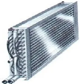
The refrigerating effect takes place in the evaporator which is done by the evaporator blower. It sucks the unwanted air out from the refrigerated area and blows it through the evaporator fins. However as the air passes through the fins and gives up its heat, it returns to the refrigerated area lot cooler and drier. A typical sample of evaporator is shown in the figure 5.
Figure 5: Evaporator of a refrigeration system.
IV.
EXPERIMENTATION WITH BASIC
REFRIGERATION SYSTEM
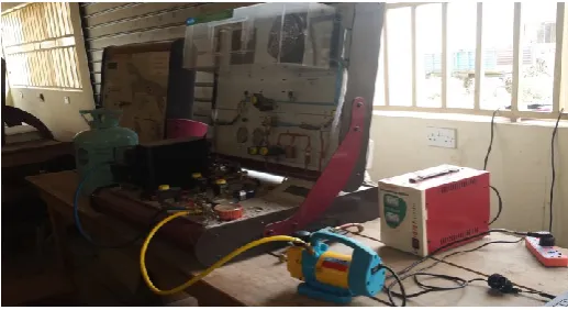
In order to operate economically, the refrigerants are used repeatedly. For this reason, the simulator is operated in a closed circuit either in a TEV or capillary mode with the support of the four major stages; that is the compression, condensation, expansion and evaporation. Figure 6 shows the operation of the simulator in Skill „G‟ laboratory of Niger Delta University.
Figure 6: Simulator Assembly
TEV mode of Operation:
The TEV is used to gauge the liquid refrigerant flow entering the evaporator at a rate equivalent to the amount of refrigerant being evaporated in the evaporator. The valves regulating this flow as shown in figure 7 provides a pressure drop in the system, separating the high-pressure side of the system from the pressure side of the system, allowing the low-pressure refrigerant to absorb heat onto itself.
Figure 7: Refrigerant Flow Path Chart
Capillary mode of Operation:
The capillary tube is designed to lower the cooling liquid pressure which was raised during the compression process. Thus, the pressure drop on the tube depends on the internal diameter and length of the tube, the flow speed, the cooling material specific weight and the friction coefficient between the cooling material and the tube. This is a fix control element, which depends on its dimensions and material.
V.
RESULT PRESENTATION
Table 1: Results for R134a
Table 2: Results for R12
Table 3: Results for R22
Table 4: Results for R600a
Figure 8: Star-pot of COP versus Stage number
Figure 9: A graph of Condenser Temperature (T3) against Stage number
0.0 0.5 1.0 1.5 2.0 2.5 3.0 3.5
0 5 10
Co
eff
ici
ent
o
f
P
er
forma
nce
Stage Number
R134a (TEV Mode) R134a (Cap. Mode) R12 (TEV Mode)
0 20 40 60 80 100
0 5 10
Co
n
d
enser
T
emp
er
atu
re
(T
3)
Stage Number
R134a (TEV Mode) R134a (Cap Mode) R12 (TEV Mode)
R12 (Cap Mode)
0 20 40 60 80
0 5 10
E
v
apo
ratio
n
T
emp
er
atu
re
(T
5)
Stage Number
R134 a (TEV)
Figure 10: Star-pot of Evaporation Temperature against Stage number
Figure 11: Condensation Temperature difference with respect to Stage number
VI.
DISCUSSION OF RESULTS
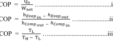
The analyzed results of the COPs are obtained using the different p – h charts for the refrigerants under study. The corresponding thermodynamic properties of the refrigerants for each process in the refrigeration system are estimated where values are evaluated using the equations below for the derivation of the COPs in the graphical plots.
COP =
…...i COP =
…...ii COP = …...iii
Established results as shown in figure 8 displays the highest COP of 3.23 of the refrigeration system as obtained in R134a (TEV mode) at stage 3 where compressor and evaporator load are in “off – mode” with evaporator fan operated at low condition. Meanwhile, a reverse condition of the operating components of the system is observed in R22 with 0.67 COP (TEV mode) at stage 6.
Consequently, the revealed results in figures 9 and 11 shows that the R134a (Cap mode) is capable of emitting up to 95℃ capacity of heat from the condenser to the surrounding air. Similarly, the results in figure 10 displays heat absorption in the evaporator. It is obvious that good refrigerating effect is observed in R134a (TEV mode), R12 (Cap mode) and R134a (Cap mode) operated in temperature range of 60 - 71℃, 38 - 40℃ and 62 -
69℃ respectively. The capillary mode of operation for the last four stages of R134a experiences a drastically fall in temperature from 64 - 17℃. This is as a result of over loading of the compressor component with application of load at the evaporator. However, as the compressor is put off in stage 8, gradual increase from 18 - 20℃ is seen.
One common occurrence observed is the unchanged suction pressure (LP) at stabilization point from the TPS simulator. At this stage the cooling effect is observed in the evaporator, and also along the low pressure pipes in the system. This is the ultimate objective of the refrigerating system.
VII.
CONCLUSION
A close look of results as obtained from the study with the varying operational stages of the different refrigerants leads to the following conclusions:
The best condition to determine the highest COP of a refrigerator is when the following components such as compressor, evaporator load and fan are at relaxation condition.
R134a refrigerant is identified as the refrigerant with the highest COP, thus it is considered the best refrigerant for the system. This is also in-line with the desirable properties for the selection of refrigerants where R134a is a member refrigerant of HFC group considered most environmental friendly with little or zero level of ozone depleting potentials. Therefore, other refrigerants under the HFC group are considered creditable since they all share the same thermodynamic properties.
The R134a and R12 are confirmed as the most suitable refrigerants to be used for domestic and industrial heating purposes respectively from established results.
Results attests that at stabilization point, the pressure of the system are good enough for suitable cooling of the system or devices, the refrigerant and the environment, etc.
Therefore, the study is justifiable hence the TPS simulator machine used for the study is a replica of the real refrigeration system for basic operation; hence results should be treated as such.
0 20 40 60 80 100
1 2 3 4 5 6 7 8
T
emp
er
atu
re
Stage Number
VIII.
ACKNOWLEDGMENT
Author sincerely acknowledged Prof. E. A. Ogbonnaya, former Head of Department of Mechanical/Marine Engineering; Niger Delta University for his unrelenting encouragement.
NOMENCLATURE
COP Coefficient of Performance
Qo Heat Extracted from cold body per cycle
Wnet Work done per cycle
h Enthalpy
TL Temperature at lower source
TH Temperature at higher source
CFC Chloro Fluoro Carbon
HCFC Hydro Chloro Fluoro Carbon
HFC Hydro Fluoro Carbon
R Refrigerant
E1 Evaporator Fan
Com Compressor
Eva Evaporator
IX.
REFERENCES
[1]. Ajoko, T.J., Refrigeration Systems for University Students. 2015, No 8 Otiotio Road, Yenegoa, Bayelsa State, Nigeria: Oshe Printing Press/Publications.
[2]. Elumalai, P., R. Vijayan, P. S.S. Srinivasan and C. Chinnaraj, An Investigation on the Performance Characteristics of Environment-Friendly Refrigerant Mixtures in a Window Air Conditioner. Middle-East Journal of Scientific Research, 2015. 23 (5): p. 987-992.
[3]. Allgood, C.C. and C.C. Lawson, Performance of R-438A in R-22 refrigeration and air conditioning systems. 2010.
[4]. Munasinghe, M. and K. King, Protecting the ozone layer. Finance and Development, 1992. 29(2): p. 24-5.
[5]. Grace, I. and S. Tassou, Simulation of the performance of alternative refrigerants in liquid chillers. Proceedings of the Institution of Mechanical Engineers, Part A: Journal of Power and Energy, 2001. 215(4): p. 429-441.
[6]. Janković, Z., I. Matić, and M. Živić, Mathematical Model of Complete Vapor Compression
Refrigeration System with Helical Coil Evaporator Flooded in the Water. Transactions of FAMENA, 2016. 40(SI-1): p. 33-46.
[7]. Gullo, P., B. Elmegaard, and G. Cortella, Energy and environmental performance assessment of r744 booster. Thermal Engineering, 2015. 87: p. 633-647.
[8]. A. Pavani, P.M. Reddy, and G.M.P. Yadav, Performance Analysis of Refrigeration System Using Various Alternative Refrigerants. Advanced Engineering and Applied Sciences: An International Journal, 2014. 4(1): p. 12-16.
[9]. Nagalakshmi, K. and G.M. Yadav, The Design and Performance Analysis of Refrigeration System Using R12 & R134a Refrigerants. Mechanical engineer at St. Jhons College of Engg &Technology, Yemmiganur-518360, A. P, India, 2014. 2.
[10]. Gullo, P., B. Elmegaard, and G. Cortella, Energy and environmental performance assessment of R744 booster supermarket refrigeration systems operating in warm climates. international journal of refrigeration, 2016. 64: p. 61-79.
[11]. Ge, Y. and S. Tassou, Thermodynamic analysis of transcritical CO 2 booster refrigeration systems in supermarket. Energy Conversion and Management, 2011. 52(4): p. 1868-1875.
[12]. Domanski, P., D. Yashar, and M. Kim. Performance of HC and HFC refrigerants in a finned-tube evaporator and its effect on system efficiency. in Natural Working Fluids Conference, 6th IIR Gustave Lorentzen. Proceedings. 2004. [13]. National Universities Commission (NUC), and
Skill 'G' Nigeria Ltd, Science and Technology Education Training Manual on Air-Conditioning and Refrigeration Training Systems for Higher Educational Institution (HEIs) and Technical Vocational Educational Training (TVET). 2015, Abuja - Nigeria: Scientific Educational Systems (SES).
![Figure 1: Refrigeration and Air Conditioning TPS Simulator. source: [13]](https://thumb-us.123doks.com/thumbv2/123dok_us/9100699.1444582/2.595.303.549.464.663/figure-refrigeration-air-conditioning-tps-simulator-source.webp)