© June 2019 | IJIRT | Volume 6 Issue 1 | ISSN: 2349-6002
IJIRT 148517
INTERNATIONAL JOURNAL OF INNOVATIVE RESEARCH IN TECHNOLOGY1042
The Art of Intelligent Control of Induction Motor Drive
Using Fuzzy Logic Controller
Devangi J Jain
1, Jigar J Jain
21
Lecturer, Electrical Engineering Dept, BBIT
2Asst. Prof, Electrical Engineering Dept, DJMIT
Abstract-In this paper Induction motors are the most important workhorse in industries and they are manu- factured in large numbers .The induction motors have mainly developed in constant speed motor drives for general purpose application. The motor drive system comprises a voltage source inverter-fed induction motor (VSIM): namely a three-phase voltage source inverter and the induction motor. The squirrel-cage induction motor voltage equations are based on an orthogonal d-q reference rotating frame where the coordinates rotate with the controlled source frequency. The paper presents a novel fuzzy logic controller for closed loop Volts/Hz induction motor drive system. Fuzzy logic is a part of artificial intelligence(AI), which is an important branch of computer science or computer engineering. The inputs to the fuzzy logic controller are the linguistic variables of speed error and change of speed error, while the output is change in switching control frequency of the voltage source inverter. In this paper a comparison between fuzzy logic controller and traditional PI controllers are presented. The results validate the robustness and effectiveness of the proposed fuzzy logic controller for high performance of induction motor drive. Simulink software that comes along with MATLAB was used to simulate the proposed model.
Index terms-Artificial Intelligence, Induction motor, PI controller, fuzzy logic controller, speed control
I. INTRODUCTION
Today three phase induction motor drives are employed in different industrial fields with a wide power range. All this drives are working without speed sensors. Simulink induction machine models are available in the literature [1-2], but they ap. pear to be black boxes with no internal details. Some of them in [1-2] recommend using S functions, which are software source codes for Simulink blocks. This technique does not fully utilize the power and ease of
Simulink because S-function programming knowledge is required to access the model variables. Another approach is using the Simulink Power System Block set [3] that can be purchased with Simulink. This block set also makes use of S-functions and is not as easy to work with as rest of the Simulink blocks. Reference [4] refers to an implementation approach similar to the' one in this paper but fails to give any details. In this paper, a modular, easy to understand Simulink induction motor model is described. With the modular system, each block solves one of the model equations. Though induction motors have few advantageous characteristics, they also posse's nonlinear and time-varying dynamic interactions [5 6], Using conventional PI controller, it is very difficult and complex to design a high performance induction motor drive system. The fuzzy logic control (FLC) is attractive approach, which can accommodate motor parametric variations and difficulty in obtaining an accurate mathematical model of induction motor due to rotor parametric and load time constant variations. The FLC is a knowledge-based control that uses fuzzy set theory and fuzzy logic for knowledge representation [7]. This paper presents a fuzzy logic controller suitable for speed control of induction motor drives.
II. INDUCTION MOTOR MODEL
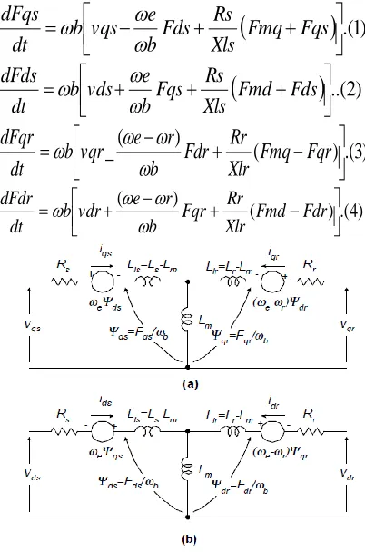
One of the most popular induction motor models derived from this equivalent circuit is Krause's model [6]. An induction machine model can be represented with four differential equations. To solve these equations, they have to be rearranged in the state-space. form, X=Ax+b Where X=[Fqs FdsFdr Fdr w r] T is the state vector.
IJIRT 148517
INTERNATIONAL JOURNAL OF INNOVATIVE RESEARCH IN TECHNOLOGY1043
.(
1
)
Fmq
Fqs
Xls
Rs
Fds
b
e
vqs
b
dt
dFqs
..(
2
)
Fmd
Fds
Xls
Rs
Fqs
b
e
vds
b
dt
dFds
)
3
.(
)
(
)
(
_
Fmq
Fqr
Xlr
Rr
Fdr
b
r
e
vqr
b
dt
dFqr
)
4
.(
)
(
)
(
Fmd
Fdr
Xlr
Rr
Fqr
b
r
e
vdr
b
dt
dFdr
Fig 1 Dynamic or d-q equivalent circuit of an induction Machine
Where d: direct axis, q: quadrature axis, s: stator variable, r: rotar variable,
vqs, vds : q & d axis stator voltages, vqr, vqr : q&d axis rotar voltages,
Fmq,Fmd : q& d axis magnetizing flux linkages Rr: rotor resistance,
Rs: stator resistance,
Xls: stator leakage reactance (we Lls), Xlr: rotor leakage reactance (we Llr)
III SIMULINK IMPLEMENTATION
The inputs of a squirrel cage induction machine are the three-phase voltages, their fundamental frequency, and the load torque. The outputs, on the other hand, are the three phase currents, the electrical torque, and the rotor speed.
The d-q model requires that all the three-phase variables be transformed to the two -phase synchronously rotating frame Consequently, the induction machine model will have blocks
transforming the three-phase voltages to the d-q frame and the d-q currents back to three-phase The induction machine model implemented in this paper is shown in Fig. 2. It consists of five major blocks: the o-n conversion, abc-syn conversion, syn-abc conversion, unit vector calculation, and induction machine d-q model blocks.
The following subsections will explain each block
A. O-N Conversion Block:
This block is required for an isolated neutral system, otherwise it can be bypassed. The transformation done by this block can be represented as follows:
(5)
B. Unit Vector Block Calculation
Unit vectors cos
e and sin
e are used in vector rotation blocks, "abc-syn conversion block" and "syn-abc conversion block". The angle e is calculated directly by integrating the frequency of the input three-phase voltages, e.e=e dt. (6)
The unit vectors are obtained simply by taking the sine and cosine of Be' This block is also where the initial rotor position can be inserted, if needed, by adding an initial condition to the Simulink "Integrator" block. Note that the result of the integration in (6) is reset to zero each time it reaches2n radians so that the angle always varies between 0 and 2n.
C. abc-syn conversion block:
© June 2019 | IJIRT | Volume 6 Issue 1 | ISSN: 2349-6002
IJIRT 148517
INTERNATIONAL JOURNAL OF INNOVATIVE RESEARCH IN TECHNOLOGY1044
where the superscript "s" refers to stationary frame
D. syn-abc conversion block:
This block does the opposite of the abc-syn conversion block for the current variables using (5) and (6) following the same implementation techniques as before.
Fig.2 Induction machine model implementation in SIMULINK
E. Induction machine d-q model block
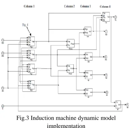
Fig.3 Induction machine dynamic model implementation
The resulting model is modular and easy to follow. Any variable can be easily traced using the Simulink
'Scope' blocks. The blocks in the first two columns calculate the flux linkages, which can be used in vector control systems in a flux loop. The blocks in Column 3 calculate all the current variables, which can be used in the current loops of any current control system and to calculate the three-phase currents. The two blocks of Column 4, on the other hand, calculate the torque and the speed of the induction machine, which again can be used in torque control or speed control loops, These two variables can also be used to calculate the output power of the machine.
IV. OPEN-LOOP CONSTANT V/HZ OPERATION
Fig. 4 shows the implementation of open-loop constant V1Hzcontrol of an induction machine. This figure has two new blocks: command voltage generator and 3-phase PWM inverter blocks. The first one generates the three-phase voltage commands, and it is nothing more than a "syn-abc" block explained earlier.
The latter first compares the reference voltage, Vref to the command voltages to generate PWM signals for each phase, then uses these signals to drive three Simulink "Switch" blocks switching between +VJ2 and -Vd/2 (Vd: dc link voltage). The open-loop constant V/Hz operation is simulated for 1.2s ramping up and down the speed command and applying step load torques.
V.CLOSED LOOP CONSTANT V/Hz OPERATION
IJIRT 144769
INTERNATIONAL JOURNAL OF INNOVATIVE RESEARCH IN TECHNOLOGY1045
Fig.4.Open loop V/Hz Operation
VI. FUZZY LOGIC CONTROLLER DESIGN
The fuzzy logic controller has been designed using the fuzzy logic GUI provided in Matlab As shown above we have the three FIS variables: Error, change in error and the output. for each of the following we defind the ranges from the data obtained and then we use the triangular membership function and have such member functions for each FIS.
MEMBERSHIP FUNCTION
SURFACE VIEWER
FUZZYLOGIC CONTROL ALGORITHM
A fuzzy algorithm consists of situation and action pairs. Conditional rules expressed in IF and THEN statements are generally used. For example, the control rule might be:
© June 2019 | IJIRT | Volume 6 Issue 1 | ISSN: 2349-6002
IJIRT 148517
INTERNATIONAL JOURNAL OF INNOVATIVE RESEARCH IN TECHNOLOGY1046
following terms are defined: error equals the set point minus the process output, error change equals the error from the process output minus the error from last output: and control input applied to the process. In addition, it is necessary to quantize the qualitative statements and the following linguistic sets are assigned
The membership function are: NG= Negative biG
NP= Negative small Z= Zero
PP= Negative PG= Negative big
TRUTH TABLE
℮→ ∆℮↓
NG NP Z PP PG
NG NG NG NP NP Z
NP NG NP NP Z PP
Z NP NP Z PP PP
PP NP Z PP PP PG
PG Z PP PP PG PG
RESULT
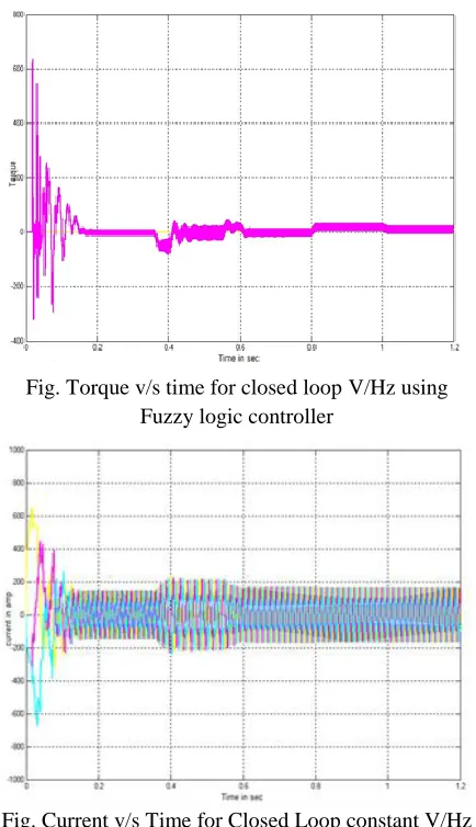
The output of the fuzzy logic controller (FLC) is used to adjust the inverter switching control frequency and the dc voltage at the inverter using a constant (VF) ratio the induction motor drive system using FLC. Results were obtained using a three phase squirrel cage induction motor with 208 volt phase to phase, 60 Hz rated frequency, 1750 rpm rated speed and ¼ Hp rated power.
Fig. Speed v/s Time for Closed Loop constant V/Hz with fuzzy logic controller
Fig. Torque v/s time for closed loop V/Hz using Fuzzy logic controller
Fig. Current v/s Time for Closed Loop constant V/Hz control with fuzzy controller
VII. CONCLUSION
This paper presents a simple, novel and robust fuzzy logic speed controller for high performance induction motor drives. The FLC does not need exact knowledge of induction motor and tolerate range load excursions and parametric variations. The control assignment rules are obtained using heuristic trial and error and human expertise. The simulation test results validate the FLC robustness for different speed trajectories.
REFERENCES
IJIRT 148517
INTERNATIONAL JOURNAL OF INNOVATIVE RESEARCH IN TECHNOLOGY1047
Processes", IEEE Trans. Systems, Man, and Cybernetics,No.3, PP.28-44,1973.
[2] N.T. M. Mohan Undeland and W.P.Robbins, "Power Electronics Converter, Applications and Design" john Wiley & Sons Inc. Canada, 1989. [3] L. Tang, M. F. Rahman, “A new direct torque
control strategy for flux and torque ripple reduction for induction motors drive – a Matlab/Simulink model,” IEEE International Electric Machine and Drives Conference,2001,pp.884-890.
[4] Bimal K. Bose,Modern Power Electronics and AC Drives, Prentice Hall, 2002.
[5] P. C. Krause, Analysis of Electric Machinary, McGraw-Hill Book Compeny,1986