DOE Based Statistical Approaches in Modeling of
Laser Processing – Review & Suggestion
Sivarao, Shukor, T.J.S.Anand & Ammar
Abstract— Design of Experiment commonly referred to as DOE is one of the extensively used methods for experimental study of many processes in engineering. It is a statistical approach in which a mathematical model is developed through experimental runs. DOE provides us the opportunity to optimize and predict possible output based on the parameters setting. In this study, a review is done on DOE techniques that have been employed for laser beam process optimization by other researches. This study predominantly focuses on the usage of response surface methodology, Taguchi’s method and factorial design in laser beam machining. A deduction is made to illustrate the significance of machining parameters to responses.
Index Term— Design of experiment, mathematical model, response surface methodology, Taguchi method, factorial design.
I. INT RODUCT ION
A. Statistical Approach
Statistical approach is a general term governing the application of a statistical model in the selected field in which it revolves a probability distribution built to facilitate deductions made from available data. A basic statistical approach is by implying design of experiment.
B. Design of Experiment
Design of Experiment or DOE for short is an experimental or analytical method that is commonly used to statistically signify the relationship between parameters to responses. DOE has a wide application especially in the field of science and engineering for the purpose of process optimization and development, process management and validation test.DOE is essentially experimental based modeling. It is a designed experimental approach which is
far superior to
unplanned approach whereby a systematic way will be used to plan the experiment, collect the data and analyze the data. A mathematical model will be developed by using analysis techniques such as ANOVA and regression analysis
whereby the mathematical model shows the relationship between the input parameters and the output responses [1].
T his work was supported in part by the University T eknikal Malaysia Melaka (UT eM) towards working on UT eM funded modeling of laser
machining project. Project number: S149.
Ir. Sivarao, Shukor, T.J.S.Anand & Ammar are the academic members of Faculty of Manufacturing Engineering, Universiti T eknikal Malaysia Melaka (UT EM), Hang T uah Jaya, 76100 Durian T unggal, Melaka, Malaysia who are currently working on modeling of machining processes.
T he correspondence author can be contacted via e-mail: [email protected] or [email protected]).
Among the most famously used DOE techniques are response surface modeling with central composite design, Taguchi’s method and factorial design.
Response surface methodology or commonly known as RSM is an anthology of statistical and mathematical methods that are helpful in generating improvement methods and optimizing a machining process. It is more frequently used in analyzing the relationship and the influences of input machining parameters on the responses.
Taguchi method is a broadly accepted method of DOE which has proven in producing high quality products at subsequently low cost. This method regularly used in automobile, electronics and other processing industry. The objective of the Taguchi method is to determine the optimum settings of input parameters, neglecting the variation caused by uncontrollable factors or noise factors. Factor here refers to an input variable whereby the state can be controlled during the experiment. Factors or factorial design are used rather time or cost during conducting experiments since it allows study of interactions between factors. Interactions are the driving force in many processes. Vital interface may be unobserved without factorial design experiments.
In a full factorial experiment, responses are measured at all combinations of the experimental factor levels. The combinations of factor levels represent the conditions at which responses will be measured. Each experimental condition is called a “run” and the response measurement is called an “observation” while factorial design can be run two-levels, three-levels and multi-level factorial. The entire set of runs is the “design”. Full factorial design is one of the good choices for most experiment whereas multi-level is expensive and unproductive.
C. Other Methodology
DOE is method that revolves around experimentation for optimization and modeling. Other methods that are commonly used for this purpose are analytic methods and Artificial Intelligence (AI) based techniques. Some of the commonly used analytic methods are exact solution and numerical solution while artificial neural network (ANN) and fuzzy logic are widely used AI techniques.
D. Advantages and Disadvantages of DOE
from that, the mathematical model generated can be used as a prediction model which can predict the possible output response based on the input values. Another main reason DOE is used because it saves time and cost in terms of experimentation. DOE function in such manner that the number of experiments or the number of runs is determined before the actual experimentation is done. This way, time and cost can be saved as we do not have to repeat unnecessary experiment runs. Most usually, experiments will have error occurring. Some of them might be predictable while some errors are just out of control. DOE allows us to handle these errors while still continuing with the analysis.
DOE is excellent when it comes to prediction linear behavior. However, when it comes to non-linear behavior, DOE does not always give the best results [2].
II. COMMON LASER EXPERIMENT AT IONS
A. Material Removal Rate
Material removal rate (MRR) values increases and then drops after a certain value for an increasing power density where it was shown in a research. This experiment was d one using Nd:YAG laser drilling machine at different densities to see the MRR of metal (aluminum, nickel, mild steel, titanium, tungsten, copper and zinc) [3]. An experimental study on micromachining of sapphire (381 mm) and silicon (533 mm) wafers shows that the MRR increases with beam energy density, disregard of the machining speed [4].
It was found through experimental studies that compressed air increases the MRR compared to argon inert gas during laser cutting of carbon fibre composites [5]. The increase of the pulsed Nd:YAG laser shows an increase of MRR for all composite type materials [6].
B. Kerf Width
An experimental study was done to investigate the effects of different assist gasses i.e. oxygen, nitrogen and argon under high pressure (up to 10 bar) on the kerf width. The observation concludes that oxygen or air produces larger kerf width while inert gas gives a smallest kerf and the kerf width increases as laser power is increases and cutting speed reduces (for CO2 cutting of 3mm thick mild steel s heet) [7]. In another experimental study on kerf width while cutting 1.2mm thick austenitic stainless steel sheet using Nd:YAG laser cutting, it was observed that an increase in the frequency reduces the kerf width [8]. Same results was observed when the effects of cutting speed, laser power and assist gas types on the kerf width were studied. There are also other studies that found similar relation between the three parameters to the kerf width [2], [22], [30], [35], [42], [62].
In a separate study, it was found that a focus setting kept on the work piece for thin sheets (1.5 mm) and inside the workpiece for thicker sheets (3.5 mm) will reduce the kerf width during CO2 laser cutting [9]. A study on Nd:YAG laser cutting of 1mm thick sheet of nickel based su peralloy shows that an increase in the spot overlap (function of cutting speed and pulse frequency) causes the kerf width to increase [10]. Shorter pulse duration also tend to yield smaller kerf taper than a longer pulse duration. In a research to study the effect of material type and its thickness on hole
taper in Nd:YAG laser drilling of titanium and nickel alloys of different thickness, the results indicated that the taper angle and hole entry diameter are varying for different materials and increasing with decreasing thickness. An increase in pulse frequency decreases taper angle while pulse energy have no significant effect on hole taper [11].
The effect of focal plane position to the hole taper was studied under fibre-glass composite using Nd:YAG laser drilling. The study concludes that for a smaller hole taper, the focal plane position with relation to the workpiece depends on the material thickness [12]. It was concluded that hole diameter increases with increasing laser power for the CO2 and Nd:YAG laser drilling of glass fibre reinforced epoxy laminates and polyester foils [13].
C. Surface Roughness
A study on surface roughness using Nd:YAG laser cutting of 1mm thick sheet of nickel based superalloy shows that surface roughness value reduces as the cutting speed and frequency were increased and laser power and gas pressure were decreased. It was also observed that nitrogen results in better surface finish compared to oxygen [10]. In a study of high power CO2 laser cutting, the value of surface roughness reduces as the nitrogen and argon gas pressure were increased but when the gas pressure of air was above 6 Bar, the surface result was poor [7]. It was also noted that a higher cutting speed produces better surface finish.
A research on CO2 laser cutting which showed that laser power and cutting speed greatly influences the surface roughness. It was observed that at an optimum feed rate, surface roughness was at minimum value while the laser power has a smaller effect on surface roughness [14]. In a CO2 laser cutting of mild steel, it was found that the surface roughness showed bad results up to 6 bar [15]. In Nd:YAG laser cutting of nickel based super-alloys, it was observed that an increasing effect of overlap spot improves the surface finish [10].
It revealed that using pulsed Nd:YAG laser for micromachining of 0.5mm thick NdFeB ceramic in water gives better surface finish compared to air [16]. The study to obtain optimum value of surface roughness suggests that the optimal parametric values to achieve this goal were pulse frequency in the range of 6 to 8.5 Hz, lamp current between 22 and 27 amp and with cutting speed in the range of 17 to 22 mm/s [17]. In a controlled fracture experiment on laser cutting of thick ceramic substrates it was observed that by using 60 W laser power (CO2 and Nd:YAG) and 1mm/s will result better surface finish compared to conventional laser cutting [18].
In two different articles on CO2 laser cutting of thick ceramic titles, the outcome shows that surface roughness is mainly affected by the ratio of power to cutting speed, material thickness and composition, type of gas and also its pressure [19]-[20]. The usage of nitrogen assist gas and lesser power intensities tends to lower the surface roughness [21]. CO2 laser cutting in pulse mode yields better surface finish than continuous wave mode [22].
D. Metallurgical Characteristics
[23]. It was also observed that an increased oxygen pressure will result in increase on HAZ. The least HAZ can be obtained by setting medium pulse energy, high cutting speed, high pulse frequency and high pressure of argon assist gas [45], [47]. The usage of oxygen seems to yield maximu m HAZ compared to nitrogen and argon.
HAZ tends to increase as the depth of hole drilling increases [24]. In an Nd:YAG laser drilling study shows that small pulse energy and material thickness results in smaller HAZ. Pulse frequency was found not to have prominent effect on HAZ in laser cutting [11]. Through investigation, it was revealed that low wavelength laser with small pulse width in pulsed laser cutting gives smaller HAZ when compared to the opposite [25].
In a research, it was found that an increase in the beam angle to the surface until a certain point will decreases the HAZ after which it will remain almost constant [26]. An increase in pulse energy and feed rate increases the HAZ but was found to decrease very little when pulse frequency is increased [27]. Based on a conducted quantitative analysis, Nd:YAG laser cutting of mullite–alumina, the observation showed that cutting speed and pulse frequency have the highest influence on HAZ [28]. Assist gas pressure was found not to have prominent effect on HAZ. The analysis shows that cutting speed is the product of gas pressure and power.
It was found in a study that laser cutting of carbon fibre composites produces more HAZ compared to electrical discharge machining (EDM) [5]. One of the aims in laser machining is to minimize the occurrence of recast layer (re-solidification of melt ejection). Increasing the pulse frequency and pulse energy reduces the recast layer with increase in material thickness [11]. Beam angle has the same effect on recast layer as it did on HAZ [26]. It is possible to completely remove the recast layer in laser cutting of thick ceramic plates at an optimum angle and distance by using a specially designed nozzle [29].
III.ST AT IST ICAL APPROACH USING DOE
DOE of laser machining is used in many areas such as laser cutting, laser drilling, laser texturing and laser micro -drilling for better understanding of the relationship between laser parameters and responses.
A. Response Surface Methodology
Response surface methodology (RSM) technique for optimization of carbon fibre reinforced plastics composite laser cutting where the reaction of HAZ and taper of the cut to cutting speed, pulse energy, pulse duration, pulse repetition and gas pressure was investigated. Cutting speed, pulse energy, pulse duration and pulse repetition were found to significantly influence the HAZ while gas pressure affects the cut kerf width the most [30]. The suggested optimal parameters for conducting the experiment were cutting speed between 0.5 to 0.8 mm/s, pulse energy 1.5 to 2 J, pulse duration in range of 0.4 to 0.7 mm/s, pulse repetition of 35 to 45 Hz and gas pressure from 5 to 7 kg/cm2.
In another RSM application investigated the influence of parameters on hole taper and circularity for two different materials, it was noted that the pulse frequency has a bigger effect on the responses for stainless steel compared to mild
steel in which the pulse frequency had no significant effect [31]. Low peak power, shorter pulse width, positive focal plane position, higher gas assist pressure, large number of pulse and lower pulse frequency produces a smaller hole entrance. Asides from that, higher peak power, moderate pulse width, positive focal plane position and higher gas assist pressure results in more cylindrical hole with less hole taper.
In an analysis of laser machining of Zirconia, RSM was utilized to determine the optimal setting for the process parameters for achieving minimum HAZ and hole taper. The analysis results shows that a minimum HAZ was obtained by using 17 amp of lamp current, 2.0 kHz of pulse frequency, 2.0 kg/cm2 assist gas pressure and 2% of the duty cycle. Minimum hole taper was also found at the same setting except for assist gas pressure which should be changed to 0.6 kg/cm2. Lamp current was found to have the most significant effect on both of the responses in which a linear increase can be obtained. Minimum HAZ and hole taper is a direct result from low current setting [17].
In a laser beam machining review paper, it was stated that CCD technique the most commonly used experimental design technique in mathematical modeling for laser machining process optimization [1]. In addition, it also affirmed that the most common research done in laser machining is experimental studies, modeling and optimization studies. In this case, the latter is used where statistical design experiment is used to show the relationship between input parameters and responses by using mathematical equation. It was also noted that there are more experiments with relation to laser machining uses a single response as objective for optimization [1].
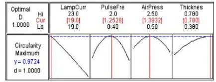
In a parametric study of pulsed Nd:YAG laser micro-drilling, the results shows that lamp current and sample thickness have noteworthy effect on the process responses, in this case the hole circularity at exit and ho le taper. The pulse frequency was found to be the governing factor that controls the hole taper while the air pressure has a higher effect on the hole circularity. For an optimum value of hole taper as shown in Fig. 1, it was suggested that a lower value of lamp current, higher value of pulse frequency, lower value of air pressure done at higher sample thickness. To obtain optimum results for both responses, moderate values of pulse frequency, air pressure and lamp current is best used on higher value of sample thickness [32].
Fig. 1. Optimization results of maximum hole circularity at exit.
air pressure of 0.13 N/mm2. The predicted responses as shown in Fig. 2 were minimum deviation of upper width by 0.0101 mm, lower width 0.0098 mm and depth at 0.0069 mm. The percentage error between the ANN predicted output and the data from the experiment are found to be within the acceptable range [33].
Fig. 2. Results obtained from analysis. GA predicted results closely resembles the experimental results
Using RSM CCD technique, a predictive model have been developed to analyze the effects of the laser power, cutting speed and compressed air pressure against the HAZ, surface roughness and dimensional accuracy for three different polymer materials (PP, PC, PMMA). The results of the experiment showed that the HAZ is directly proportional to the laser power and inversely proportional to cutting speed and compressed air pressure. It was observed that the quality of cut of PMMA is much better than PC and PP. Surface roughness is found to be inversely proportional to all the parameters with cutting speed and compressed air has more influence on it than laser power. The dimensional deviations for all measured dimensions were around 0.07 mm [34].
There was an investigative study made to find the effects of the laser parameters to the responses for laser transmission welding of acrylic. The process parameters studied were laser power, welding speed, clamp pressure and size of the beam. The responses investigated are lap -shear strength and weld seam width. The results shows that lap shear strength and weld seam width can be increased by increasing the laser power meanwhile an increase in welding speed will reduce the values of both responses [35]. Clamp pressure was mentioned to have a positive effect on both responses. The stand-off distance determines the size of the beam. As such, both responses increase with the increase in the stand-off distance. However, at some stages, further increase in stand-off distance will only reduce the strength.
A study on laser texturing by combining RSM CCD technique and Taguchi method was done to identify the key parameters that contribute to productivity and surface quality. The results of their study show that frequency and energy of the pulse have the most influence in the laser texturing process. MRR is linearly proportional to pulse energy and frequency while the surface roughness is inversely affected by them. The increase of quadratic terms effects in the pulse energy and frequency leads to an increase in surface roughness value and a decrease in MRR. The optimal setting for the pulse frequency and energy are 12.5 kHz and 5 mJ respectively. It is predicted that the model can function with a 95% confident level [36].
In a multi-response optimization study done on laser welding of austenitic stainless steel, the effects of laser
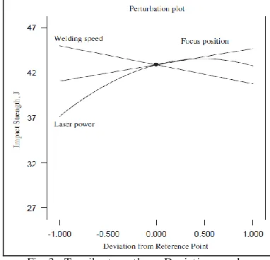
power, welding speed and focal point position on the tensile strength, impact strength and joint-operating cost were observed. In the article, it was noted that the laser power increases the tensile strength until it reaches a central value after which the tensile strength began to drop. The tensile strength is not greatly affected by the focal distance on low welding speeds. As such, a better tensile strength can be obtained if high welding speed is used, it was suggested that the focal distance is at its lower limit. An increas e in the laser power will increase the impact strength while the opposite occurs if the welding speed is increased. A more focused laser beam was also found to improve the impact strength. It was also mentioned that the welding operating cost would be reduced 43% if an optimal machining conditions are used which produces acceptable mechanical properties [37]. Fig. 3 below shows tensile strength versus deviation graph.
Fig. 3. T ensile strength vs. Deviation graphs
B. Taguchi’s Method
In a Taguchi’s method based experiment aiming to find the optimal condition for improving the hole quality. It was found that number of pulses, standoff distance, gas pressure and nozzle diameter have a significant effect on the hole circularity [38]. An increase in number of pulses tend to increase the hole exit diameter and reduce the hole taper.
In a laser drilling study the effects of machining parameters on recast layer and micro-crack formation were investigated by means of Taguchi method. Pulse energy was demonstrated to have two effects with high value reducing micro-cracking and low value reduces recast layer. A short pulse width reduces the occurrence of delamination and micro-cracking. However, it was also noted there is a fair dependency between pulse energy and width o n the responses. A gas pressure of 70 psi was found to reduce all three responses [39].
analysis to obtain the optimum values for the parameters. They concluded that the gas pressure of 2kg/cm2, pulse width 0.6ms, pulse frequency value 23Hz and cutting speed value of 20 mm/min for optimum value control. The optimum level for the kerf width, kerf deviation and kerf taper are 0.246mm, 0.01mm and 0.2728º. Fig. 4 shows the percentage of contribution of each parameter on the responses.
Fig. 4. T he percentage of contribution of each parameter on the responses [1]
In an experimental study carried out on laser parameters effects for cutting QFN. Taguchi’s orthogonal array method was used in order to find the optimum combination of the parametric values. The effect of laser current, laser frequency and cutting speed on the laser cutting quality i.e. width of HAZ and cutting line was examined. The study showed that 95.47% of the laser cutting quality is primarily influenced by three factors [41]. The three factors were laser frequency by 51.828%, laser current by 20.484% and cutting speed by 23.157%. A low range of laser frequency will yield incomplete cutting while a very high frequency will cause over-cutting and higher width of HAZ. Further analysis on the data showed that the optimal setting for the laser current, laser frequency and cutting speed were 29 A, 2 kHz and 2 mm/s respectively. Fig. 5 shows ANOVA analysis data that indicates the fraction of contribution by the parameters.
Fig. 5. ANOVA analysis of the data that shows the fraction of contribution by the parameters (Chen H. L. et al., 2006)
An integrated approach whereby the combination of ANN technique and Taguchi’s algorithms were used in optimizing the CO2 laser welding process to obtain the optimal setting for the welding speed, laser power and focal positioning for the responses; fuse-zone width and HAZ width. The results obtained where the optimal setting achieve through training the neural network were 1.42, 70 and 2.5 respectively for
the parameters. The output values were recalculated to be 2.22 and 9.70 respectively [38]. Fig. 6 shows neutral network for dimensional calculation.
Fig. 6. Neural network for dimensional calculation
A study on the effects of laser cutting of aluminum by investigating the effects of laser power, cutting speed, pulse frequency and assist gas pressure on the responses i.e. kerf width, edge roughness and size of heat affected zone (HAZ) reveals that high value of laser power coupled with low cutting speed will result in a negative effect on the kerf width and HAZ. However, a low power setting will also result in rougher surface cut but on the other hand, higher value of gas assist pressure will result in smoother surface cut. Cutting speed affects kerf width the most followed by gas assist pressure [42].
C. Factorial Analysis
In a factorial analysis performed for optimizing the cutting of titanium using Nd:YAG laser process, the effects of type of assist gas, pulse energy and overlapping rate on the surface roughness and dross formation were investigated. Their study found that superficial hardness of the cut area increases as well as a noticeable formation of nitrogen precipitates under a thin layer of a melted zone [43]. They concluded that gases He, Ar and their mixtures does not produce precipitation and also does not emphasize on the hardness of the material. The surface roughness value increases with higher pulse energy, with intermediate value suggested for usage. Increases the overlapping quantity on the other hand increases the dross formation but reduces roughness.
A parametric study using factorial design method was applied to study the effect of pulse length, focus setting, energy and material thickness on hole diameter and taper. The thickness of the work piece was found to be the most important criteria. Pulse length influences hole diameter the most but focus setting is even more important for an improved hole geometry with increase focus setting. An increase in pulse energy found to increase the hole diameter also [44].
IV. CONCLUSION
HAZ is directly proportionally to power, where increase in power will result in an increase in HAZ and it works in the opposite for the cutting speed. Higher laser frequency will cause over cutting and higher width of HAZ.
Surface roughness reduces as cutting speed and frequency increases while laser power and gas pressure decreases.
Pulse width and cutting speed affects kerf width the most followed by gas assist pressure. High laser power and low cutting speed will show a negative effect on the kerf width. Inert gasses produces smaller kerf width compared to oxygen. An increase in frequency reduces kerf width.
MRR increases with pulse energy and frequency. MRR increases with laser power but only until a certain point.
V. FUT URE RESEARCH DIRECT ION
Albeit being highly useful in modeling and optimizing data, there are some set back in using DOE for process analysis. A recently popular and more versatile approach through artificial intelligence, AI can be used for future studies. AI is used in engineering problems for the forecast or estimation of the process behavior. AI model such as ANN is able to learn, adapt to changes and copy human thought process with little human connection contrary to DOE that req uires full human handling.
ACKNOWLEDGMENT
The authors would like to extend their sincere thanks to the top level management of manufacturing engineering faculty, the lab coordinator and lab technicians for their continuous help and support throughout the experimental and research period of this work.
REFERENCES
[1] Avanish, K. D. & Vinod, Y. (2007). “Laser Beam Machining – A Review.” International Journal of Machine Tools & Manufacture. vol. 48. pg 609 – 628.
[2] “Statistical Design of Experiments” retrieved April 19, 2010, from http://www.doesinc.com/.
[3] Voisey, K.T . et al. (2000). “Quantification of melt ejection phenomena during laser drilling.” Materials Research Society. vol 617. pg J5.6.1–J5.6.7.
[4] T ahmouch, G. et al. (1997). “Cutting by a high power laser at a long
distance without an assist gas for dismantling.” Optics and Laser
Technology. vol 29(6). pg 307–316.
[5] Lau, W.S. & Lee, W.B. (1992). “Pulsed Nd:YAG laser cutting of carbon fibre composite materials.” Annals of CIRP. vol 39(1). pp 179–182.
[6] Lau, W.S. et al. (1995). “Un-conventional machining of composite materials.” Journal of Materials Processing Technology. vol 48. pp 199–205.
[7] Chen, S.-L. (1999). “The effects of high-pressure assistant -gas flow on high power CO2 laser cutting.” Journal of Material Processing
Technology. vol 88. pg 57–66.
[8] Ghany, K.A. & Newishy, M. (2005). “Cutting of 1.2mm thick austenitic stainless steel sheet using pulsed and CW Nd:YAG laser.”
Journal of Material Processing Technology. vol 168. pg 438–447.
[9] Karatas, C. et al. (2006). “Laser cutting of steel sheets: influence of workpiece thickness and beam waist position on kerf size and stria formation.” Journal of Material Processing Technology. vol 172. pg 22–29.
[10] T hawari, G. et al. (2005). “Influence of process parameters during pulsed Nd:YAG laser cutting of nickel-base superalloys.” Journal of
Materials Processing Technology. vol 170. pg 229–239.
[11] Bandyopadhyay, S. et al. (2002). “Geometrical features and
metallurgical characteristics of Nd:YAG laser drilled holes in thick IN718 and T i–6Al–4V sheets.” Journal of Materials Processing
Technology. vol 127. pg 83–95.
[12] T uersley, I.P. et al. (1998). “Nd-YAG laser machining of SiC fibre/borosilicate glass composites, part II. T he effect of process variables.” Com posites Part A 29A (1998) 955–964.
[13] Vitez, Z.I. (2000). “Laser processing of adhesives and polymeric materials for microelectronics packaging applications.” Proceedings
of the 4th IEEE International Conference on Adhesive Joining and
Coating Technology in Electronics Manufacturing. pg 289–295.
[14] Rajaram, N. et al. (2003). “CO2 laser cut quality of 4130 steel.”
International Journal of Machine Tools and Manufacture. vol 43. pg
351–358.
[15] Chen, S.-L. (1998). “ T he effects of gas composition on the CO2 laser cutting of mild steel.” Journal of Materials Processing
Technology. vol 73. pg 147–159.
[16] Kruusing, S. et al. (1999). “Micromachining of magnetic materials.”
Sensors and Actuators. vol 74. pg 45–51.
[17] Kuar, A.S. et al. (2005). “Experimental investigations on Nd:YAG laser cutting of silicon nitride.” International Journal of
Manufacturing and Managem ent. vol 2–4. pg 181–191.
[18] T sai, C.-H. & Chen, H.-W. (2003). “ Laser cutting of thick ceramic substrates by controlled fracture technique.” Journal of Materials
Processing Technology. vol 136. pg 166–173.
[19] Black, I & Chua, K. L. et al. (1997). “ Laser cutting of thick ceramic
tile.” Optics & Laser Technology. vol 29(4). pg 193–205.
[20] Black, I. et al. (1998). “A laser beam machining (LBM) database for the cutting of ceramic tile.” Journal of Materials Processing
Technology. vol 84. pg 47–55.
[21] Al-Sulaiman, F.A. et al. (2006). “CO2 laser cutting of a carbon/carbon multi lamelled plain-weave structure.” Journal of
Material Processing Technology. vol 173. pg 345–351.
[22] Lum, K.C.P. et al. (2000). “CO2 laser cutting of MDF 1.
Determination of process parameter settings.” Optics & Laser
Technology. vol 32. pg 67–76.
[23] Wang, J. & Wong, W.C.K. (1999). “CO2 laser cutting of metallic coated sheet steels.” Journal of Materials Processing Technology.
vol 95. pg 164–168.
[24] Araujo, D. et al. (2003). “Microstructural study of CO2 laser
machined heat affected zone of 2024 aluminium alloy.” Applied
Surface Science. vol 208–209. pg 210–217.
[25] Zhang, G.H. et al. (2007). “An experimental study on laser cutting
mechanisms of polycrystalline diamond compacts.” Annals of CIRP.
vol 56(1). pg 201–204.
[26] Sezer, H.K. et al. (2006). “Effect of beam angle on HAZ, recast and oxide layer characteristics in laser drilling of T BC nickel superalloys.” International Journal of Machine Tools and
Manufacture. vol 46(15). pg 1972–1982.
[27] Zhang, J.H. et al. (1996). “Investigation of the surface integrity of laser-cut ceramic.” Journal of Materials Processing Technology vol 57. pg 304–310.
[28] Quintero, F. et al. (2004). “Quantitative evaluation of the cuts performed on mullite-alumina by Nd:YAG laser.” Optics and Lasers
in Engineering. vol 42. pg 327–340.
[29] Quintero, F. et al. (2006). “Optimization of an off-axis nozzle for assist gas injection in laser fusion cutting.” Optics and Lasers in
Engineering. vol 44. pp 1158–1171.
[30] Mathew, J. et al. (1999). “Parametric studies on pulsed Nd:YAG laser cutting of carbon fibre reinforced plastic composites.” Journal
of Materials Processing Technology. vol 89–90. pg 198–203.
[31] Ghoreishi, M. et al. (2002). “Comparative statistical analysis of hole
taper and circularity in laser percussion drilling.” International
Journal of Machine Tools and Manufacture. vol 42. pg 985–995.
[32] Biswas R. et al. (2009). “A Parametric Study of Pulsed Nd:YAG
Laser Micro-Drilling of Gamma-T itanium Aliminide.” Optics &
Laser Technology. vol. 42. pg 23 – 31.
[33] Dhupal D. et al. (2009). “Modeling and Optimization on Nd:YAG Laser T urned Micro–Grooving of Cylindrical Ceramic Material.”
Optics and Lasers in Engineering. vol. 47. pg 917 – 925.
[34] Choudhury, I. A. and S. Shirley. (2009). “ Laser Cutting of Polymeric Materials: An Experimental Investigation.” Optics &
Laser Technology. vol. (NA), no. (NA), pp (NA).
[35] Bappa Acherjee et al. (2009). “ Prediction of weld strength and seam width for laser transmission welding of thermoplastic using response surface methodology.” Optics & Laser Technology. . vol. 41. pg 956 – 967.
[36] Soveja A. et al. (2008). “Optimization of TA6V Alloy Surface Laser
T exturing Using an Experimental Design Approach.” Optics and
Lasers in Engineering. vol. 46. pg 671 – 678.
[37] Benyounis K. Y. et al. (2008). “Multi–response optimization of CO2 laser–welding process of austenitic stainless steel.” Optics & Laser
Technology. vol. 40. pg 76 – 87.
[38] Masmiati, N. & Philip, P.K. (2007). “Investigations on laser percussion drilling of some thermoplastic polymers.” Journal of
[39] Corcoran, L. et al. (2002). “T he laser drilling of multi-layer
aerospace material systems.” Journal of Materials Processing
Technology. vol 123. pg 100–106.
[40] Avanish, K. D. & Vinod, Y. (2008). “ Multi-Objective Optimization of Nd:YAG Laser Cutting of Nickel-Based Superalloy Sheet Using Orthogonal Array With Principal Component Analysis.” Optics and
Lasers in Engineering. vol. 46. pg 124 – 132.
[41] Chen, H. L. et al. (2007). “ Study of optimal laser parameters for cutting QFN packages by T aguchi’s matrix method.” Optics & Laser
Technology. vol 39. pg 786–795.
[42] Stournaras, A. et al. (2009). “ An investigation of quality in CO2 laser cutting of aluminum.” Journal of Manufacturing Science and
Technology. vol. 2. pg 61–69.
[43] Almeida, I. A. & S. Shirley. (2006). “Optimization of T itanium Cutting by Factorial Analysis of T he Pulsed Nd:YAG Laser Parameters.” Journals of Materials Processing Technology. vol. 179. pg 105 – 110.
[44] Yilbas, B.S. (1996). “Parametric study to improve laser hole drilling process.” Journal of Materials Processing Technology. vol 70. pg 264–273.
[45] Chen, T .-C. & Darling, R.B. (2005). “ Parametric studies on pulsed near ultraviolet frequency tripled Nd:YAG laser micromachining of sapphire and silicon.” Journal of Materials Processing Technology. vol 169. pg 214–218.
[46] Chen, Y.H. et al. (1996). “Application of T aguchi method in the
optimization of laser micro engraving of photomasks.” International
Journal of Materials and Product Technology. vol 11(3–4). pg 333–
344.
[47] Cosp, J.P. et al. (2002). “Laser cutting of high-vitrified ceramic
materials: development of a method using a Nd:YAG laser to avoid catastrophic breakdown.” Materials Letters. vol 55. pg 274–280. [48] Dauer, S. et al. (1999). “Rapid prototyping of micromechanical
devices using Q-switched Nd:YAG laser with optional frequency doubling.” Sensors and Actuators. vol 76. pg 381–385. [49] Duley, W.W. & Gonsalves, J.N. (1974). “CO2 laser cutting of thin
metal sheets wit h gas jet assist.” Optics and Laser Technology. vol 1. pg 78–81.
[50] Grevey, D.F. & Desplats, H. (1994). “Comparison of the performance obtained with a YAG laser cutting according to the source operation mode.” Journal of Material Processing
Technology. vol 42. pg 341–348.
[51] Kuar, A.S. et al. (2006). “Modeling and analysis of pulsed Nd:YAG laser machining of zirconia (ZrO2).” International Journal of
Machine Tools and Manufacture. vol 46(12). pg 1301–1310.
[52] Lamikiz, L.N.L. et al. (2005). “CO2 laser cutting of advanced high
strength steels (AHSS).” Applied Surface Science. vol 242. pg 362– 368.
[53] Li, L. et al. (2007). “Crouse, Striation-free laser cutting of mild steel sheets.” Annals of CIRP. vol 56(1). pg 193–196.
[54] Lim, S.-H. et al. (2006). “A study on optimal cutting condition of a high speed feeding type laser cutting machine by using T aguchi method.” International Journal of Precision Engineering and
Manufacturing. vol 7(1). pg 18–23.
[55] Olabi, A. G. et al. (2006). “An ANN and T aguchi Algorithms
integrated approach to the optimization of CO2 laser welding.”
Advances in Engineering Software. vol 37. pg 643 – 648.
[56] Prasad, G.V.S. et al. (1998). “Laser cutting of metallic coated sheet steels.” Journal of Materials Processing Technology. vol 74. pg 234–242.
[57] Raghavendra, R. & Vinod, Y. (2009). “ Multi-Objective Optimization of Nd:YAG Laser Cutting of T hin Superalloy Sheet Using Grey Relational Analysis With Entropy Measurement.”
Optics & Laser Technology. vol. 41. pg 922 – 930.
[58] Rao, B.T . et al. (2005). “Processing of concretes with a high power CO2 laser.” Optics and Laser Technology. vol 37. pg 348–356. [59] Rao, B.T . et al. (2005). “Inert gas cutting of titanium sheet with pulsed mode CO2 cutting.” Optics and Lasers in Engineering. vol 43. pg 1330–1348.
[60] Shanjin, L. & Yang, W. (2006). “ An investigation of pulsed laser cutting of titanium alloy sheet.” Optics and Lasers in Engineering.
vol 44. pg 1067–1077.
[61] T am,S.C. et al. (1992). “Application of T aguchi method in the
optimization of the laser-cutting process.” Journal of Materials
Processing Technology. vol 29. pg 63–74.
[62] T am, S.C. et al. (1993). “Optimization of laser deep-hole drilling of Inconel 718 using the T aguchi method.” Journal of Materials
Processing Technology. vol 37. pg 741–757.
![Fig. 4. The percentage of contribution of each parameter on the responses [1]](https://thumb-us.123doks.com/thumbv2/123dok_us/1394649.1651005/5.596.67.265.156.331/fig-percentage-contribution-parameter-responses.webp)
