Conversion Systems Using Three Phase Boost Rectifiers
M. A. Hossain
1*, N. Afrin
2, M. Feroz Ali
31
Department of Electrical and Electronic Engineering, Jessore University of Science and Technology, Jessore - 7408, Bangladesh
2,3
Dept Department of Electrical and Electronic Engineering, Pubna University of Science and Technology, Pabna, Bangladesh
Abstract: - Wind energy is an important source of electrical power in recent years. d summarize the content of the paper. Its main advantage comes from the fact of being a renewable and environmental-friendly energy. Permanent magnet synchronous generators (PMSG) applied to wind energy conversion system (WECS) using variable speed operation is being used more frequently in wind turbine application. Variable speed systems have several advantages over the traditional method of operating wind turbines, such as the reduction of mechanical stress and an increase in energy capture. To allow the variable speed operation of the PMSG WECS a conventional three-phase bridge rectifier (BR) with a bulky capacitor associated with a voltage source current controlled inverter (VS-CCI) is used. This paper presents a comparative simulation study between three different approaches applied to harmonic mitigation in PMSG WECS. The studied techniques are single-switch three-phase boost rectifier and three-phase boost type PWM rectifier.
Keywords: - Harmonic mitigation, PMSG, WECS, Bridge rectifier, Boost rectifier
I. INTRODUCTION
Figure 1. Wind Energy Conversion System.
A software simulation model developed in using PSIM software, which allows easy performance evaluations, is used to estimate the behavior of these three different schemes associated with the PMSG WECS. Simulation results showed the possibility of achieving maximum power tracking, output voltage regulation and harmonic mitigation simultaneously.
II. WIIND TURBINE MODEL
The In a wind turbine system, the kinetic energy in the wind is converted into rotational energy in a rotor of the wind turbine. The rotational energy is then transferred to a generator, either directly or through a gearbox for stepping up the rotor speed. The mechanical energy is then converted to electrical energy (variable-frequency, variable-voltage) by the generator. From the generator, the electrical energy is transmitted to a utility grid either directly or through an electrical energy conversion stage that produces frequency, constant-amplitude voltage suitable for interface to the utility. The WECS considered in this work consists of a PMSG driven by a fixed pitch wind turbine; an AC-DC energy conversion stage implemented using three different approaches and a VS-CCI. The entire system is shown in Fig. 1. A brief description of each element of the system is given below. The output power of the wind turbine is given by the equation.
3 2
1
C
(
,
)
AV
P
m
p
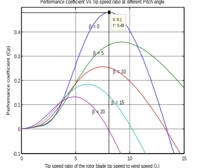
(1)The Cp curve for the wind turbine used in this study is shown in Fig. 2. The wind turbine output mechanical torque is affected by the Cp.
0 5 10 15
-0.1 0 0.1 0.2 0.3 0.4 X: 8.1 Y: 0.48
Performance coefficient Vs Tip speed ratio at different Pitch angle
Tip speed ratio of the rotor blade tip speed to wind speed ()
P e rf o rm a n c e c o e ff ic ie n t (C p )
= 0
= 5
= 10
= 15
= 20
Figure 2. Power coefficient vs. Tip speed ratio with =0, 5, 10, 15, 20 degree
Figure 3. Implemented sensor-less VS-CCI WECS.
III. HARMONICANALYSISBYBOOSTERRECTIFER
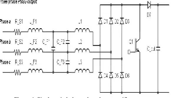
Winds are caused by the uneven heating of the atmosphere by the sun, the irregularities of the earth's surface, and rotation of the earth. Wind is a renewable resource because it is inexhaustible. It is a result of the sun shining unevenly on the earth. Since wind turbine output is proportional to the cube of the wind speed, the wind turbine generator output fluctuates due to wind speed variations. The loading characteristic of the PMSG WECS can be easily simulated by connecting an adjustable load resistor to the PMSG and rectifier terminal. In order to extract the peak power from the WTG at a given wind speed, the WECS has to match closely to the maximum power curve. One of the possible power factor correctors (PFC) approaches, suitable to implement the input rectifier, the black block shown in Fig. 3, was the three-phase DCM boost rectifier proposed by Prasad and Ziogas [3]. The control of the DC power output is easily made by duty cycle control. Only a single active device such as a MOSFET or IGBT is needed. The main disadvantages of this implementation are the increasing of the power losses in the devices comparing with the conventional three-phase AC-DC converter and the necessity of an additional input filter to remove the high-frequency harmonic components of the input currents [3, 4]. Therefore, the implementation of the input rectifier using a single-switch three-phase boost rectifier will result in harmonic mitigation on the PMSG output currents. The complete schematic diagram of the three-phase DCM boost rectifier is shown in Fig. 4. Inductors L1, L2, and L3 have the same small value, such as they operate in the discontinuous conduction mode in conjunction with diodes D1 – D6. At the end of the transistor Q1 conduction subinterval, the inductor currents reach peak values, which are also proportional to the applied three-phase line-to-neutral voltages. When transistor Q1 turns off, then diode D7 becomes forward-biased and the inductors discharge their stored energies to the DC output. Since the peak input currents are proportional to the applied input line-to-neutral voltages, then the average values of the input currents are also approximately proportional to the input line-to-neutral voltages [4].
Figure 5. Three-phase bridge rectifier input currents.
Figure 6. Three-phase PMSG output currents and line-to-line voltage divided by 6 using 3-Phas Boost Rectifier.
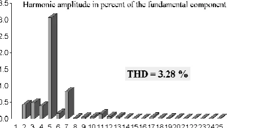
Figure 7. Harmonic content of the PMSG current output using Three-Phase Boost Rectifier.
The three-phase PMSG output currents and also the line-to-line voltage (divided by 6) are represented in Figure 6. The PMSG output current harmonic content is shown in figure 7.
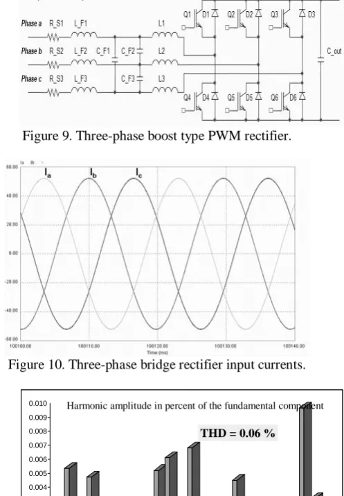
low THD at any operation point. Hence, it will be investigated in this work. The inductors and capacitor filter the high-frequency switching harmonics, and have little influence on the low frequency AC components of the waveforms. The three-phase boost type PWM rectifier shown in Fig. 9. The three-phase bridge rectifier input currents are shown in figure 10. From this figure, it is easy to observe the CCM and the very good results obtained. The PMSG output current harmonic content is shown in figure 11.
Figure 9. Three-phase boost type PWM rectifier.
Figure 10. Three-phase bridge rectifier input currents.
0.000 0.001 0.002 0.003 0.004 0.005 0.006 0.007 0.008 0.009 0.010
1 2 3 4 5 6 7 8 9 10 11 12 13 14 15 16 17 18 19 20 21 22 23 24 25
THD = 0.06 %
Harmonic amplitude in percent of the fundamental component
Figure 11. Harmonic content of the PMSG output current using Three-Phase Boost Rectifier.
V. CONCLUSION
REFERENCES
[1] K. Tan and S. Islam, "Optimum Control Strategies in Energy Conversion of PMSG Wind Turbine System Without Mechanical Sensors", IEEE Transactions on Energy Conversion, Vol. 19, No. 2, June 2004, pp. 392-400.
[2] Phipps, J.K.;"A transfer function approach to harmonic filter design", Industry Applications Magazine, IEEE , Volume: 3 , Issue: 2 , March-April 1997, pp.:68 – 82.
[3] A. R. Prasad, P. D. Ziogas, and S. Manias, “An active power factor correction technique for three-phase diode rectifiers,” in PESC’89 Rec., pp. 58–65.
[4] Robert W. Erickson, “Some Topologies of High Quality Rectifiers” Keynote paper, First International Conference on Energy, Power, and Motion Control, May 5-6, 1997, Tel Aviv, Israel, pp. 1-6.
[5] Kaboli, Sh.; Zolghadri, M.R.; Homaifar, A., “Effects of sampling time on the performance of direct torque controlled induction motor drive”, IEEE International Symposium on Industrial Electronics, 2003. ISIE '03, Volume: 2 , June 9-11, 2003, pp.:1049 – 1052
[6] Yao Tze Tat, "Analysis of Losses in a 20kW Permanent Magnet Wind Energy Conversion System", in the Department of
[7] Electrical and Computer Engineering. Western Australia: Curtin University of Technology, October 2003. pp. 101.
BIOGRAPHY
M. Amzad Hossain is pursuing MSc Engg degree in department of electrical and electronic Engineering in Rajshahi University of Engineering & Technology, Rajshahi Bangladesh in 2010. Presently he is working in department of Electrical and Electronic Engineering in Jessore University of Science and Technology, Bangladesh, Mr. Hossain is actively involved in study, research, teaching and consulting project works with undergraduate students. His research interests in renewable energy and power system stability.
N. Afrin has obtained his BSc Engg degree in Electrical and Electronic Engineering from Rajshahi University of Engineering & Technology, Bangladesh in 2012. Presently she is working in department of electrical and Electronic Engineering in Pabna University of Science and Technology, Pabna, Bangladesh. Her research interests in renewable energy and optical communication.