Wind Analysis of a Multi Storied Building with
Basic Wind Speeds
K. N. V. J. Suryanarayana Raju Potnuru Manoj
M. Tech Student M.E Student
Department of Civil Engineering Department of Civil Engineering Andhra University College of Engineering Andhra University College of Engineering
Dr. Shaik Yajdani Associate Professor Department of Civil Engineering Andhra University College of Engineering
Abstract
The present study describes the effect of wind on a multi storied building. It deals with the analysis of G+10 multi storied framed structure for different wind speeds such as 33m/sec, 39m/sec, 44m/sec, 47m/sec, 50m/sec, 55m/sec using Staad-pro. Four different frames are considered, two in longitudinal direction and two in transverse direction. They are analysed for gravity and wind loading with different load combinations as per IS:875 part-1and part-2 and IS875 part-3.These frames are compared with different wind speeds, and members in one storey are compared with another storey for a particular wind speed and corresponding results are drawn for critical load combination. All the above results will be studied thoroughly to draw conclusions. Sample design calculations were done for randomly chosen set of columns and beams in those frames.
Keywords: basic wind speeds, wind load, multi-storey r/c building, staad-pro
_______________________________________________________________________________________________________
I. INTRODUCTION
Buildings are defined as structures utilized by the people as shelter for living, working or storage. In 21ST century due to huge population the number of areas in units is decreasing day by day. Few years back the population was not so vast so they used to stay in horizontal system (due to large area available per person). But nowadays, people prefer vertical system (high rise building due to shortage of area). In high rise buildings we should be concerned about all the forces that act on the building the beam, column reinforcements and joint detailing should be good enough to counteract these forces successfully. As nowadays there is shortage of land for building more buildings at a faster growth in both residential and industrial area the vertical construction is given due importance because of which tall buildings are being built on a large scale.
Wind in general has two main effects on the tall buildings. 1) It exerts forces and moments on the structure and its cladding.
2) It distributes the air in and around the building mainly termed as wind pressure. Sometimes because of unpredictable nature of wind it takes so devastating form during some wind storms that it can upset the internal ventilation system when it passes into the building. For these reasons the study of air-flow is becoming integral with the planning a building and its environment.
This analysis mainly deals with the study of a regular building with six different basic wind speeds i.e. 33m/sec, 39m/sec, 44m/sec, 47m/sec, 50m/sec, 55m/sec using Staad pro. A 20.96mm × 19.43mm G+10 storey structure is modeled using staad pro. The height of each storey is taken as 3.45m; making to height of structure is 37m. Loads considered are taken in accordance with IS-875(part1, part2) IS-1893(2002) code. Post analysis of the structure, maximum shear forces, bending moment and storey maximum displacement are computed and then compared for all the analyze cases.
II. METHOD OF ANALYSIS
Code based procedure for wind analysis:
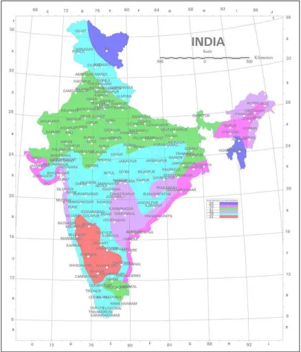
The basic wind speed for any site shall be obtained from Fig 3.1 and shall be modified to include the following effects to get design wind speed, Vz at any height, Z for the chosen structure: (a) Risk level, (b) Terrain roughness and height of structure, (c) Local topography, and (d) Importance factor for the cyclonic region. It can be mathematically expressed as follows:
V
z = Vb k1 k2 k3 k4. Where,
V
z = design wind speed at any height z in m/s k
k
2 = terrain roughness and height factor (see 5.3.2), k
3 = topography factor (see 5.3.3), and k
4 = importance factor for the cyclonic region (see 5.3.4).
NOTE: The wind speed may be taken as constant up to a height of 10 m. However, pressures for buildings less than 10m high may be reduced by 20% for stability and design of the framing.
Fig. 1: Risk coefficients for different classes of structures in different wind speeds zones
III. MODELLING AND ANALYSIS
39m/s
44m/s
47m/s
50m/s
55m/s
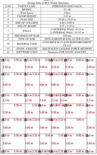
Design characteristic: The following design characteristic are considered for multi-storey structure Table – 1
Design Data of RCC Frame Structures
S.NO PARTICULARS DIMENSION/SIZE/VALUE
1 MODEL G+10
2 Wind Speed 33m/s
3 FLOOR HEIGHT 3.45 m
4 PLAN SIZE 20.96 x 19.43 m
5 SIZE OF COLUMNS 0.60 x 0.60 m
6 SIZE OF BEAMS 0.45 x 0.30 m
7 WALLS 1) EXTERNAL WALL =0.23 m
2) INTERNAL WALL =0.115 m
8 THICKNESS OF SLAB 120 mm
9 TYPE OF SOIL TYPE-II,MEDIUM SOIL AS PER IS-1893
10 MATERIAL USED CONCRETE M-25 AND REINFORCEMENT
FE-415
11 STATIC ANALYSIS EQUIVALENT LATERAL FORCE METHOD
12 SOFTWARE USED Staad.pro FOR STATIC ANALYSIS
IV. RESULTS AND GRAPHS
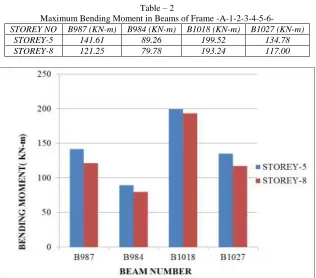
Table – 2
Maximum Bending Moment in Beams of Frame -A-1-2-3-4-5-6-STOREY NO B987 (KN-m) B984 (KN-m) B1018 (KN-m) B1027 (KN-m)
STOREY-5 141.61 89.26 199.52 134.78
STOREY-8 121.25 79.78 193.24 117.00
Fig. 5: Maximum Bending Moment in Beams of Frame A-1-2-3-4-5-6-7
Table – 3
Maximum Shear Force In Beams For Frame -A-1-2-3-4-5-6-7 STOREY NO B987 (KN) B984 (KN) B1018 (KN) B1027 (KN)
STOREY-5 125.32 79.42 139.99 107.79
STOREY-8 123.96 77.20 138.994 106.474
Fig. 6: Maximum Shear Force In Beams For Frame -A-1-2-3-4-5-6-7
Table – 4
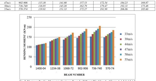
Maximum Bending Moment in Continous Beams for Different Wind Speeds of Frame A-1-2-3-4-5-6-7 Wind
speed
Beam No. s
Storey-10 (KN-m)
Storey-8 (KN-m)
Storey-6 (KN-m)
Storey-4 (KN-m)
Storey-2 (KN-m)
Storey-G (KN-m)
33m/s 1400-1404 108.96 128.73 137.30 145.84 153.14 148.27
39m/s 1234-1238 111.42 133.76 145.10 156.14 165.15 156.60
47m/s 902-906 115.30 141.80 157.53 172.54 184.23 169.87
50m/s 736-740 116.95 145.20 162.79 179.47 192.31 175.48
55m/s 570-574 119.91 151.33 172.27 191.99 206.86 185.60
Fig. 7: Maximum Bending Moment in Continous Beam for Different Wind Speeds of Frame A-1-2-3-4-5-6-7
Table – 5
Maximum Shear Force in Continous Beams for Different Wind Speeds of Frame A-1-2-3-4-5-6-7
Wind speed Beam No. s Storey-10 (KN) Storey-8 (KN) Storey-6 (KN) Storey-4 (KN) Storey-2 (KN) Storey-G (KN)
33m/s 1400-1404 101.42 121.25 123.96 126.65 128.92 127.33
39m/s 1234-1238 102.20 122.90 126.50 129.98 132.79 130.03
44m/s 1068-1072 102.96 124.49 128.94 133.19 136.49 132.63
47m/s 902-906 103.45 125.54 130.54 135.30 138.95 134.33
50m/s 736-740 103.98 126.65 132.25 137.55 141.56 136.10
55m/s 570-574 104.93 128.66 135.34 141.60 146.26 139.44
Table – 6
Maximum Displacement in Continous Beams for Different Wind Speeds of Frame A-1-2-3-4-5-6-7
Wind speed Beam No. s Storey-10 (mm) Storey-8 (mm) Storey-6 (mm) Storey-4 (mm) Storey-2 (mm) Storey-G (mm)
33m/s 1400-1404 30.02 28.05 24.31 18.78 11.69 4.72
39m/s 1234-1238 38.13 36.07 31.15 23.76 14.17 4.82
44m/s 1068-1072 47.72 44.18 38.10 28.88 16.81 4.96
47m/s 902-906 53.58 49.64 42.78 32.34 18.63 5.07
50m/s 736-740 58.73 55.52 47.84 36.10 20.63 5.20
55m/s 570-574 71.37 66.25 57.08 42.98 24.33 5.46
Fig. 9: Maximum Displacement in Continous Beams for Different Wind Speeds of Frame A-1-2-3-4-5-6-7
Table – 7
Maximum Bending Moment in Columns for Different Wind Speeds of Frame A-1-2-3-4-5-6-7 Wind
speed
Column No. s
Storey10 (KN-m) Storey-8 (KN-m) Storey-6 (KN-m) Storey-4 (KN-m) Storey2 (KN-m) Storey-G (KN-m)
33m/s 376 47.93 39.38 49.30 45.56 44.59 32.75
39m/s 374 48.12 42.76 39.29 53.36 53.66 49.57
44m/s 372 48.31 33.86 42.66 60.86 62.38 65.74
47m/s 370 48.43 48.15 58.07 65.79 68.12 76.38
50m/s 368 48.55 50.43 61.91 71.05 74.23 87.72
55m/s 366 48.79 54.54 68.83 80.54 85.26 96.24
Table – 8
Maximum Shear Force In Columns For Different Wind Speeds Of Frame-A-1-2-3-4-5-6-7
Wind speed Column No. s Storey-10 (KN ) Storey-8 (KN ) Storey-6 (KN ) Storey-4 (KN ) Storey-2 (KN ) Storey-G (KN )
33m/s 12 21.92 20.26 22.49 23.86 24.25 23.97
39m/s 10 22.58 21.39 25.09 27.93 29.76 30.78
44m/s 8 23.22 22.48 27.58 31.83 35.07 37.33
47m/s 6 23.63 23.19 29.22 34.40 38.56 41.63
50m/s 4 24.08 23.95 30.97 37.15 42.29 46.22
55m/s 2 24.88 25.33 34.13 42.09 49.00 54.50
Fig. 11: Maximum Shear Force in Column for Different Wind Speeds of Frame A-1-2-3-4-5-6-7
Table – 9
Maximum Displacement in Column for Different Wind Speeds of Frame A-1-2-3-4-5-6-7
Wind speed Column No. s Storey-10 (mm) Storey-8 (mm) Storey-6 (mm) Storey-4 (mm) Storey-2 (mm) Storey-G (mm)
33m/s 376 28.50 25.74 22.26 16.51 9.33 1.64
39m/s 374 37.38 34.71 29.46 21.88 12.31 2.02
44m/s 372 46.06 42.90 36.51 27.15 15.24 2.41
47m/s 370 51.81 48.33 41.18 30.65 17.19 2.68
50m/s 368 57.97 54.14 46.19 34.40 19.29 2.92
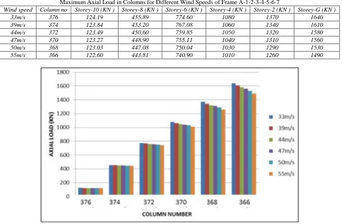
Table – 10
Maximum Axial Load in Columns for Different Wind Speeds of Frame A-1-2-3-4-5-6-7
Wind speed Column no Storey-10 (KN ) Storey-8 (KN ) Storey-6 (KN ) Storey-4 (KN ) Storey-2 (KN ) Storey-G (KN )
33m/s 376 124.19 455.89 774.60 1080 1370 1640
39m/s 374 123.84 453.20 767.08 1060 1340 1610
44m/s 372 123.49 450.60 759.85 1050 1320 1580
47m/s 370 123.27 448.90 755.11 1040 1310 1560
50m/s 368 123.03 447.08 750.04 1030 1290 1530
55m/s 366 122.60 443.81 740.90 1010 1260 1490
Fig. 13: Maximum Axial Load in Columns for Different Wind Speed of Frame A-1-2-3-4-5-6-7
V. CONCLUSION
The bending moment for a continuous beam in a frame for a storey-5 is more than bending moment for the same frame in storey-8
The Shear force for a continuous beam in a frame for a storey-5 is more than shear force for the same frame in storey-8
The moment in beams for the basic wind speed of 55 m/sec is more when compared to basic wind speeds 33m/sec, 39m/sec , 44m/sec , 47m/sec , 50m/sec.
The Shear force in beams for the basic wind speed of 55 m/sec is more when compared to basic wind speeds 33m/sec, 39m/sec, 44m/sec, 47m/sec, 50m/sec.
The displacement in beams for the basic wind speed of 55 m/sec is more when compared to basic wind speeds 33m/sec, 39m/sec, 44m/sec, 47m/sec, 50m/sec.
The bending moment in columns for the basic wind speed of 55 m/sec is more when compared to basic wind speeds 33m/sec, 39m/sec, 44m/sec , 47m/sec , 50m/sec.
The shear force in columns for the basic wind speed of 55 m/sec is more when compared to basic wind speeds 33m/sec, 39m/sec, 44m/sec , 47m/sec , 50m/sec.
The displacement in beams for the basic wind speed of 55 m/sec is more when compared to basic wind speeds 33m/sec, 39m/sec , 44m/sec , 47m/sec , 50m/sec.
The axial force in columns decreases with decreases in wind speed.
REFERENCES
[1] Arvind Y.Vyavahare, Godbole P. N. Trupti Nikose,"Analysis of Tall building for across Wind Response ' International journal of civil and structural Engineering, VOL 2 no3, 2012.
[2] Auto S.M., "Wind load estimation of Tall buildings part1: Comparison of Russian and Nigerian code of practice" Asian Journal of civil Engineering (Building and housing) Vol7, no3 (2006).
[3] Abdur Rahman, saiada Fuadi Fancy, Shamim Ara Bobby" Analysis of drift due to wind loads and earthquake loads on tall structures by programming language c" International journal of Scientific & Engineering Research , volume 3, Issue 6, june-2012.
[6] Islam & Siddique , Murshed " Sustainable development in drift control of Tall buildings",4th annual paper meet and 1st Civil Engineering Congress, December 22-24, 2011.
[7] IS: 456-2000 plain and Reinforced concrete code of practice, Fourth revision.