Technology (IJRASET)
Design Optimization and Analysis of Leaf Spring
Using Static Load Conditions
Mahesh Dasgaonkar1, Abhishek Hambar2, P Baskar3
School of Mechanical Engineering, Vellore Institute of Technology (VIT University), Vellore, Tamilnadu
Abstract - A leaf spring is the simplest type of suspension system, widely used in heavy commercial vehicles. The leaf spring is a structural member and acts as an energy absorbing system on the virtue of its deflection. In this research work leaf springs are analyzed using finite element methods considering different parameters. Parameters considered in the analysis are the material of the leaf spring and two different model geometries. This paper includes the study of deflection and stress distribution of leaf spring for heavy duty vehicles, considering various recent materials and change in the thickness of the leaf springs. The results highlight the best suitable material for leaf spring and its design optimization.
Keywords - Leaf spring, Heavy commercial vehicle, Finite element method, Static structural analysis
I. INTRODUCTION
A leaf spring is an elastic energy absorbing body, used as suspension system in heavy duty vehicles. The important function of the leaf spring is to deflect when loaded and come back to its original position when the load is removed. Leaf spring generally takes care of the load and vibration induced due to road surface irregularities. Leaf springs are generally monitored on the basis of its deflection attributes and ability to store and absorb the strain energy. Leaf spring used in automotive vehicles is generally of semi-elliptic form. In the construction of leaf spring, it is generally composed of number of curved plates, called leaf of the spring. The leaves of the spring are reducing in its length. The largest leaf is called master leaf; other leaves are called graduated leaves. All the leaves are assembled together with the help of the steel straps, nut and bolt. The leaf spring is on the Axle of the vehicle with its ends attached to chassis frame. One of its ends is rigidly attached to the frame and other one is connected to chassis frame by shackle. The main purpose of shackle is to adjust the spring length when the road wheel comes across the road irregularities. That generally means, front end of the leaf spring is fixed and constrained in all directions while the rear end is constrained only in Y and Z directions and not in X-direction.
Technology (IJRASET)
Fig.1. Leaf springII. PROBLEM IDENTIFICATION
A. Weight of the structural steel leaf spring is comparably high.
B. Deflection attributes are poor in case of structural steel.
C. Poor ride properties due to the noise and friction.
III. OBJECTIVE
A. To reduce weight of structural steel leaf spring by using other alloys and composite material.
B. To improve the deflection attributes of leaf spring.
C. To improve the ride properties and passenger comfort.
IV. CORRELATION PARAMETERS
A. Spring stiffness
Stiffness is generally expressed as ratio of force to deflection. As, K = force / deflection
Spring stiffness is important parameter to monitor spring deflection and its attributes.
B. Equivalent stress
Stress is the second important element for leaf springs. Equivalent Stress generally co-relate with durability of leaf springs.
C. Strain Energy
Strain energy is the energy stored in the elastic body under loading condition. Strain energy is the third co-relation parameter to compare the leaf springs with different materials.
V. LOAD CALCULATION
Vehicle Name : Tata SFC 407 For Rated Load Condition,
Gross Vehicle Weight : 5000kg
Total Weight (N) : 5000*10=50000 No. of leaf springs : 4
Load on each spring : 50000/4=12500 N For Over Load Condition,
Gross Vehicle Weight : 5000kg Load carried : 3000kg
Total Weight (N) : 8000*10=80000 No. of leaf springs : 4
Load on each spring : 80000/4=20000 N
VI. MATERIAL SELECTION
Technology (IJRASET)
TABLE.I. MECHANICAL PROPERTIES OF MATERIALS
VII. MODELING AND ANALYSIS
[image:4.612.68.547.271.404.2]In the present work leaf spring of heavy duty commercial vehicles is taken for modeling and analysis, to compute and compare results. The 3D modeling of leaf spring is carried out using SOLIDWORKS 2013. Figures given below show one of the models of leaf spring used in analysis.
TABLE.II. DIMENSION OF THE LEAF SPRING
A. Finite Element Analysis
Multi-leaf spring, with seven leaves used for heavy commercial vehicles, has been analyzed using finite element methods. The analysis is carried out in ANSYS 16.0 workbench to evaluate the stress distribution and deflection attributes. Each model is analyzed statically with same loading conditions for four different materials viz. structural steel, Titanium alloy (Ti-6Al-4V), E-Glass epoxy fiber, S-E-Glass epoxy fiber. The basic steps followed in finite element analysis are shown in the following flowchart (fig.4).
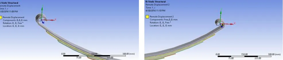
[image:4.612.62.555.554.660.2]B. Boundary Conditions
Figure 2 and Figure 3 show boundary conditions employed in front and rear ends of leaf spring. The front end is fixed to the frame and allowed to displace only in Z-direction (rotation). The rear end is connected to the frame with shackle and allowed to displace in X-direction (translation) and in Z-direction (rotation).
Fig.2. Boundary Conditions at front end Fig.3. Boundary Conditions at rear end
Properties Structural Steel Titanium Alloy E-Glass fiber composite S-Glass fiber composite
Density(g/cc) 7.85 4.43 2.57 2.48
Modulus of Elasticity(Mpa) 200000 113800 73500 86900
Poisson's Ratio 0.3 0.342 0.22 0.22
Tensile Yield Strength(Mpa) 250 880 2050 --
Parameters Dimensions for Model-1 Dimensions for Model-2
Total span of leaf spring(mm) 1180 1180
Width of each leaf(mm) 50 50
Thickness of master leaf(mm) 6 8
Thickness of graduated leaves(mm) 5,5.22,5.63,5.75,5.87 7,7.33,7.75,7.89,7.94,7.98
No. of leaves 7 7
Rated load (N) 12500 12500
Technology (IJRASET)
Fig.4. Flow chart of FEA Analysis
C. Meshing
Mesh generation process is one of the important processes in finite element analysis. Meshing discretize entire model into very small elements. In this work “fine mesh” is selected for meshing the 3D model of the leaf spring.
Fig.5. Meshing of 3D Model-1
Technology (IJRASET)
Fig.8.Deflection in E-Glass fiber composite Fig.9.Deflection in S-Glass fiber composite The above four figures shows the deflection in four different materials for model-1.The deflection attributes of model-2 are similar to that of model-1; hence the figures are not shown. As seen from the above figures, to show the deflection attributes “model with undeformed wireframe model” option is selected. The wireframe model shows the undeformed shape and colorful model shows the deformed shape.
The following results shows stress distribution of four different materials for model-1 and rated load conditions of the leaf spring.
Fig.10. Stress in structural steel Fig.11. Stress in Titanium Alloy
Fig.12. Stress in E-Glass Fiber composite Fig.13. Stress in S-Glass Fiber composite The above four figures show stress distribution using four different materials for model-1considering rated load condition. The stress generally concentrates in the red color area highlighted on the master leaf.
VIII. RESULTS AND DISCUSSION
Using ANSYS Workbench 16.0, leaf spring is analyzed for static load for model-1 and model-2 with four different materials viz. structural steel, Titanium alloy, E-glass fiber composite, S-glass fiber composite. The results obtained are plotted in graphical and tabular format.
Technology (IJRASET)
The graph 1 and graph 2 shows the linear variation of deflection with thickness of the leaves for model-1 with rated and overloads conditions. The line of deflection for E-Glass Fiber composite shows higher deflections and steeper than the lines of deflection for other materials.
TABLE.III.DEFLECTION IN LEAF SPRING
Table 3 shows the values of deflection for model-1 and model-2 using both rated load and over load conditions. The deflection in titanium alloy (overload condition) is comparable to deflection in E-Glass fiber (rated load condition).
[image:7.612.177.438.395.558.2]TABLE.IV. STRESS IN LEAF SPRING
Table 4 shows the values of stress for each model using rated load and over load conditions. It is observed that the stress developed is slightly higher in model-1 as compared to model-2 due to lower thickness of leaves in case of model-1.
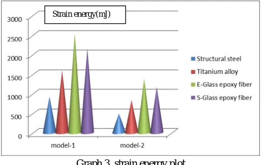
Graph.3. strain energy plot
Above plot compares strain energies for models. For model-1 strain energy is higher as its energy storing capacity is higher on the virtue of its deflection.
TABLE.V. MASS COMPARISON OF LEAF SPRING Sr.
No.
Model name
Deflection in Structural steel
Deflection in Titanium alloy
Deflection E-Glass fiber composite
Deflection S-Glass fiber composite
Rated Load Over Load Rated Load Over Load
Rated
Load Over Load Rated Load
Over Load
1 Model-1 38.64 61.83 67.79 108.47 105.44 168.71 89.18 142.69
2 Model-2 21.64 34.62 37.96 60.75 59.03 95.05 49.93 79.89
Sr.
No. Model name Stress in Structural steel Stress in Titanium alloy
Stress E-Glass fiber
Stress in S-Glass fiber
Rated Load
Over
Load Rated Load
Over Load Rated Load Over Load Rated Load Over Load 1 Model-1 692.75 1108.4 689.17 1102.7 697.96 1116.7 697.96 1116.7
2 Model-2 646.86 1035 640.9 1025.4 656.61 1050.6 656.61 1050.6
Materials Mass of Model-1(kg) Mass of Model-2(kg)
Structural Steel 12.51 17.17
Titanium Alloy 7.06 9.69
E-Glass fiber 4.09 5.62
Technology (IJRASET)
fiber exhibits lowest value of mass and thus superior ride properties and higher fatigue life.IX. CONCLUSION
A. Leaf spring model with S-Glass fiber and E-Glass fiber material have lower mass compared to structural steel and titanium alloy. Total mass of S-Glass Fiber composite , E-Glass fiber composite, Titanium alloy, structural steel considering model-1 as reference is 12.51 kg, 7.06 kg, 4.09 kg, 3.95 kg respectively.
B. Under same static load,stress in composite leaf spring is slightly more than structural steel leaf spring.
C. Under same static load, deflection in E-Glass fiber and S-Glass fiber is comparably more than conventional structural steel leaf spring.
D. Composite leaf spring exhibits greater deflections giving better ride properties and comfort due to its lower mass and higher deflection rate.
E. It is Observed that strain energy in E-Glass Fiber composite is higher as compared to other materials due to its energy storing capacity on virtue of its deflection.
REFERENCES
[1]A Srinivas Kurna, Arpit Mathur, and Sandeep Sharma, “Investigation of Stresses and Deflection in Multi Stage Leaf Spring of Heavy Duty Vehicle by FEM and Its Experimental Verification”, SAE Technical paper, year 2015
[2]Murathan Soner, Metin Tanoglu, Nilay Guven, Mustafa Karaagac, Rasim akyali, Ozay Aksoy, Tolga Erdogus and Ahmet Kanbolat, “Design and Fatigue Life Comparison of Steel and Composite Leaf Spring”, SAE Technical paper, year 2012
[3]Pengbo Wang, Chongliang Zhang and Yongquan Liu, “Simulation and Design of Leaf Spring Characteristics”, SAE Technical paper, year 2009
[4]Subhash Chandrabose, C. Thamotharan, P. Naveenchandran and R. Anbazhagan, “Design Optimization and Analysis of a Parabolic Leaf Spring”, Middle-East Journal of Scientific Research, year 2014
[5]Rupesh N. Kalwaghe, Prof. K. R. Sontakke, “Design and Analysis of Composite Leaf Spring by Using FEA and ANSYS”, International Journal of Scientific Engineering and Research, year 2015
[6]Shahrukh Shamim, Jamil Anwer, “Design and optimization of Automotive multi leaf spring by finite element method”, international journal of research in aeronautical and mechanical engineering,year 2014