6
I
January 2018
Experimental Work on Automatic Pneumatic
Bumper
Prof. Harshal Rahate1
1,
Mechanical Engineering Department, Savitribai Phule Pune University
1,
Assistant Professor, P.K. Techanical Campus, Chakan
Abstract: The technology of pneumatics has gained tremendous importance in the field of workplace rationalization and automation from old-fashioned timber works and coal mines to modern machine shops and space robots. It is therefore important that technicians and engineers should have a good knowledge of pneumatic system, air operated valves and accessories. The aim is to design and develop a control system based an intelligent electronically controlled automotive bumper activation system is called “AUTOMATIC PNEUMATIC BUMPER”. This system is consists of Ultrasonic sensor, Control Unit, Pneumatic bumper system. The Ultrasonic sensor is used to detect the obstacle. There is any obstacle closer to the vehicle (within 90 cm), the control signal is given to the bumper activation system. The pneumatic bumper system is used to product the man and vehicle. This bumper activation system is only activated the vehicle speed above 40-50 km per hour. This vehicle speed is sensed by the proximity sensor and this signal is given to the control unit and pneumatic bumper activation system.
Keywords: Pneumatic, automatic pneumatic bumper, Ultrasonic sensor
I. INTRODUCTION
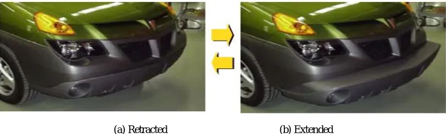
Today India is the most important underdeveloped country in the world. India is the largest country in the use of various type of vehicles. As the available resources to run these vehicles like quality of roads, and unavailability of new technologies in vehicles are causes for accidents. The number of peoples which are dead during the vehicle accidents is also very large as compared to the other causes of death. Though there are different causes for these accidents but proper technology of bumper system and technology to reduce the damage during accident are mainly effect on the accident rates. So today implementation of proper bumper system to prevent the accidents and pneumatic bumper system to reduce the damage is must for vehicles. To achieve this system modification goal, we design this Pneumatic Bumper system. We have pleasure in introducing our project “AUTOMATIC PNEUMATIC BUMPER”, which is fully equipped by Ultrasonic sensors circuit and Pneumatic bumper activation circuit. It is a genuine project which is fully equipped and designed for Automobile vehicles. This forms an integral part of best quality. This product underwent strenuous test in our Automobile vehicles and it is good. In this project, another conceptual crash preparation feature, called extendable and retractable bumper (E/R bumper), is presented. The E/R bumper is normally in the stowed position. When a high-risk of frontal impact crash is detected, the bumper extends to provide additional crush space. Recall that in a frontal impact crash accident, the kinetic energy of a motor vehicle is rapidly converted into work by plastic deformation of vehicle structures. During this energy conversion process, the vehicle is decelerated in a relatively short time and distance. The stopping distance, which is a function of the available crush space and the crush efficiency of the front-end of a vehicle, is a good crash severity indicator. For vehicles involved in similar crash impact conditions, elementary physics ensures that those with less crush space and lower crush efficiency will have shorter stopping distances, higher average deceleration, and hence, more severe crash outcomes.
[image:2.612.88.524.588.719.2]II. PROBLEMSTATEMENT
In conventional vehicles there are different mechanism operated for braking system like hydraulic, pneumatic, air, mechanical, etc. But all these braking mechanisms receive the signal or input power directly from the driver so it totally manual operated. When the driver saw the obstacle or any vehicle in front of his driving vehicle, he was irritated or becomes mazy. Due to this the driver fails to give the proper input to braking system and proper working is not occurs. Also the driver may not able to pay the full attention during night travelling so there are many chances to accidents. After the accident occurs, there is no any provision to minimize the damages of vehicles. In currently used vehicles generally bumpers used are of rigid types. These bumpers have specific capacity and when the range of the accidental force is very high then the bumpers are fails and these force transferred towards the passengers. So this system never reduces the damage of both vehicle and passengers.
III. OBJECTIVES
The future of any industry is more than just developing new technology. It is integrating shifting the approach to achieve safety. Pneumatic Bumper System approach represents considerable shift from the traditional approach to safety, by considering safety in terms of firstly, avoiding the possibility of accidents, and secondly, protecting occupants when a crash is unavoidable, we can prevent more accidents, save more lives, decrease material damage to vehicles and reduce medical costs to society.
A. Following are the main objectives of Automatic System with Pneumatic Bumpers:
1) To increase the crashing distance during accident.
2) To increase the safety during pre-crash.
3) To increase external safety to vehicle body.
4) To decrease the level of passenger injury by use of external vehicle safety device.
5) To reduce the requirement of internal safety devices like air bags.
IV. SCOPE
A. This system may be applicable in all types of light vehicles like cars, Rickshaws, Tempos.
B. This system also successfully installed in the heavy vehicles like buses, trucks, trailers, etc.
C. System able to increase the pre-crash safety.
D. System able to provide more safety to the passengers.
E. System plays an important role to save human life in road accidents.
F. To avoid the percentage of passenger injury by using external vehicle safety.
G. To reduce the requirement of internal safety devices like air bags.
V. NEEDFORAUTOMATION
Automation can be achieved through computers, hydraulics, pneumatics, robotics, etc., of these sources, pneumatics form an attractive medium for low cost automation. The main advantages of all pneumatic systems are economy and simplicity. Automation plays an important role in mass production. For mass production of the product, the machining operations decide the sequence of machining. The machines designed for producing a particular product are called transfer machines. The components must be moved automatically from the bins to various machines sequentially and the final component can be placed separately for packaging. Materials can also be repeatedly transferred from the moving conveyors to the work place and vice versa.
Nowadays almost all the manufacturing process is being atomized in order to deliver the products at a faster rate. The manufacturing operation is being atomized for the following reasons.
A. To achieve mass production
B. To reduce man power
C. To increase the efficiency of the plant
D. To reduce the work load
E. To reduce the production cost
F. To reduce the production time
G. To reduce the material handling
H. To reduce the fatigue of workers
VI. EXPERIMENTALWORK A. Details of Calculation
For calculations V. B. Bhandari and Design Data Book were used as reference material Suitable value in certain cases were taken directly, as per empirical relations or from standard values and from internet. Formulas used for calculations are as below;
1) Calculation of pneumatic cylinder dimensions: assumption maximum force acting on bumper is assumed to be 90 n Considering factor of safety as 1.25,
we design bumper for 90 x 1.25 =112.5 N force
Also, pressure used is 4 bar =0.4N/mm2
For Bumper For Out-Stroke
F o/s = P x A
112.5=0.4 x /4 (D2)
112.5= 0.4 x 0.7854 (D2)
D2 = 358.0978 mm2
So D= 18.92mm
Selecting standard value of 20mm bore diameter We calculate inner diameter.
Assuming In-stroke force to be equal to outstroke force, we assume in stroke force to be 90N. For factor of safety of 1.25, in stroke force is 90x1.25=112.5N.
For in-stroke,
Piston rod area = π/4 x d2 Effective area = π/4 x (D2-d2)
= 0.7854 x (202-d2) mm2 So,
F i/s = 0.4 x 0 .7854 x (202-d2)
112.5 = 0.31416 x (202-d2)
On solving, we get d= 6.47mm
Hence, selecting from standard values, inner diameter is 8 mm
So, for both the double acting pneumatic cylinders, bore diameter is 20mm.
To increase the crashing distance in case of accidents, we increase the stroke length of cylinder used for extending the bumper. So, for piston stroke of 90 mm is suitable.
2) Calculation of Braking distance
Braking distance, Db = [v2/(2 x μ x g)] m
Where,
v = Velocity before applying brakes (App 10 km/hr = 2.78 m/s)
μ = coefficient of friction = 0.7 (for dry surfaces)
g = acceleration due to gravity (9.81m/sec2)
Braking distance, Db = [2.782/(2 x 0.7 x 9.81)]
=0.5618 m
6.1.IMPACT FORCE CALCULATION
Force, F = mass (m) x acceleration (a) Mass of the vehicle m= 10kg
By motion Equation, 2as = v2-u2
Where,
v= Final velocity = 2.78 m/s a= acceleration,
u= Initial velocity = 0
2xax 0.5618 = 2.782 – 02
a = 6.87 m/s2
Force, F = mx a =10 x (6.87)= 68.7N The Final impacting force value F = 68.7 N
VII. FABRICATION
A. Frame
[image:5.612.113.502.202.376.2]As shown in fig. initially frame is constructed in rectangular shape (900×600) mm by welding angle bar. Then the four angle bar of 600mm is welded to main rectangular frame in order to mount all other components.
Fig 7.1 Frame
B. Frame with Axle And Wheels
The axle is subjected to turning operation up to required diameter i.e. 20mm. Turning is done for seating the ball bearing. Ball bearings are mounted on both end of the axle to give support to the axle and reduce frictions for rotation. The wheels are mounted on both ends of the axle as shown in fig.
[image:5.612.132.482.442.715.2]C. Drilling Operation
[image:6.612.119.496.102.376.2]Holes are drilled according to the dimension considered for prototype, in order to mount all other components as shown in figure.
Fig 7.3 Drilling Operation
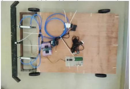
D. Assembling all the components
All the components are assembled at their proper position. A proper mounting method is used to mount the components.
[image:6.612.81.533.410.720.2]E. CATIA Model of Automatic Pneumatic Bumper
Fig7.5 CATIA V5Model of Automatic Pneumatic Bumper
REFERENCES
[1] “Automobile Engineering”, G.B.S. Narang, Khanna Publishers, Delhi, 1991, pp 671. [2] “Automobile Engineering” William H. Crowse.
[3] Pneumatic Control System----Stroll &Bernaud, Tata McGraw Hill Publications, 1999. [4] Pneumatic System----Majumdhar, New Age India International (P) Ltd Publishers, 1997.
[5] Wang J.T. & Browne, A.L. ,”Extendable & Retractable Knee Bolser ,” Paper No.323, the 2003 ESV Conference [6] Wang J.T. 1999, “Bumper Energy Absorber.” U.S. Patent No. 5,967,573.
[7] Wang J.T. & Jones G.L., 2001, “Self-Locking Telescoping Mechanism.” U.S. Patent No. 6,302,458..