International Journal of Emerging Technology and Advanced Engineering
Website: www.ijetae.com (ISSN 2250-2459, ISO 9001:2008 Certified Journal, Volume 8, Issue 3, March 2018)294
Multilocation Process Control Using PLC and
SCADA with SMS Alert
Tanvi Shinde
1, Prof.(Dr). V.A.Shah
21 M.Tech Student (Instrumentation and Control Engineer) at Dharamsinh Desai University,Nadiad
2 Head. Dept. of Instrumentation & Control, Faculty of Technology, Dharamsinh Desai University ,Nadiad, India.
Abstract— Because of rapid growth in industries since last few years, India is emerging as a leading manufacturing hub. Stoppage or problem in one plant area will affect the production in consecutive downstream process also. One probable solution is close and continuous monitoring of different processes from a single location and rectifies the problem before it occurs. It can improve the plant consistency and reliability.
One methodology to overcome this engineering challenge is to adopt a large single controller to control different processes simultaneously in different plant areas. Inthis case monitoring and control becomes quite easy. But unfortunately problem in controller or its instrumentation panel will stop the process in whole plant. This is not acceptable in any case.
In this paper, this completed to control two different but interconnected processes with the help of two different PLCs (Programmable Logic Controller). But in thiscproject, are use only one centralized SCADA (Supervisory Control and Data Acquisition) system. The SCADA software is communicate with two different PLCs with multidrop master- slave protocol. Actual process conditions of both the processes are displayed on SCADA screens simultaneously and can be issued supervisory commands as well. On the top of that, a GSM based SMS is also completed for an alert to process engineer for any abnormal condition.
Keywords—PLC, SCADA, GSM Model, temperature sensor (rtd).
I. INTRODUCTION
It has different kinds of industries around us, starting from chemical to pharmaceutical and steel to fertilizer. Almost all the industries have continuous process plants. Manufacturing is done day and night. This mass production is achieved, now a days using highest level of industrial automation. Things are produced without or minimum manual intervention. Machines are replacing human being in the industrial manufacturing processes.
This industrial automation is divided into different levels. All the levels have different device groups. Level 0 automation is Sensor-Actuator level. Devices in this level i.e. sensors, transmitters, actuators, final control elements etc. are very near to the physical system. Level 1 is a controller level. Different controllers like PLC (Programmable Logic Controller), PAC (Programmable Automation controller) and DCS (Distributed Control System) reside in this level. They are programmable devices. Controllers control the plant according to the programming done at the time of commissioning and instructions coming from higher level. Level 2 automation is a supervisory level. SCADA (Supervisory Control and Data Acquisition) resides in this level. It is a software level. It gives operator interface. The plant operator is informed about the actual situation of the plant with the help of user friendly GUI (Graphical User Interface). At the same time plant operator can also issue commands to the controller. This is a computer software layer between the operator and plant.
The level 2 of automation pyramid have ample amount of scope for improvements and innovations. Traditionally the SCADA software is installed on personal computer which is a stationary device. Today is an era of smart phone and tablets. These devices have an operating system which supports variety of software. SCADA software can be developed for this kind of handheld devices to supervise the plant activities. The main advantage of this is mobility, the engineer or operator is not supposed to be stationary in control room. Using Wi-Fi network connectivity, the process can be monitored and controlled from anywhere in the plant. It gives more operational flexibility to an operator.
Aim:
International Journal of Emerging Technology and Advanced Engineering
Website: www.ijetae.com (ISSN 2250-2459, ISO 9001:2008 Certified Journal, Volume 8, Issue 3, March 2018)295
II. SYSTEM OPERATIONInternational Journal of Emerging Technology and Advanced Engineering
Website: www.ijetae.com (ISSN 2250-2459, ISO 9001:2008 Certified Journal, Volume 8, Issue 3, March 2018)296
Working Of System:The process in the PLC is monitored and supervisory controlled using SCADA software. Unfortunately PLC is having RS485 serial communication port and PC with RS232. So, for the interfacing of PLC and SCADA, we are used RS232 to RS485 converter. Set point for temperature will be issued from the SCADA at the same time live process values of all these of parameters are monitored in the SCADA screen. it is used SIEMENS S7-
200 PLC (224 CPUs) and SIEMENS S7-200 PLC (222 CPUs) along with EM235 analog expansion module and Citect SCADA software.
Explanation:
TABLE III
A N A L O G I N
PUT-OUTPUT
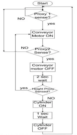
In this process, It is control temperature of the heating plate using PID algorithm. In which It is using inbuilt PID instruction for programming. IR proxy senses the metal object. After 10 sec of sensing the object, cylinder pushed the object from the heating plate.
[image:3.612.371.578.141.244.2]➢ For process 1:
TABLE I
DIGITAL INPUT-OUTPUT
In this process, we are using timer and counter for some reasons like, timers are used for checking objects are ok or not and also for different purpose. And counter is used for how many objects are sensed with the sensor1 for continuous process.
➢ For process 2:
FIGURE 2:
FLOW CHARTAI AO DI DO
RTD Heater IR
proximity sensor
Cylinder
DI DO
Three IR proximity Conveyor(motor)
[image:3.612.399.530.369.599.2]International Journal of Emerging Technology and Advanced Engineering
Website: www.ijetae.com (ISSN 2250-2459, ISO 9001:2008 Certified Journal, Volume 8, Issue 3, March 2018)297
III. HARDWARE PART USED COMPONANTsingle phase synchronous motor:
FIGURE 3: wiring diagram of single phase synchronous motor
A revolving field can be produced in synchronous motors from a single-phase source by use of the same method as for single-phase induction motors. With the main stator winding connected directly to the supply, an auxiliary winding may be connected through a capacitor.
IV. IMPLEMENATATION
As per implementation we are using two PLC running model with SCADA. Temperature transmitter, pneumatic cylinder, pneumatic valve, RTD PT100, IR proximity sensor, Heater, SMPS, etc. One valve is using implement to control the cylinder (ON & OFF). The operation of the system is programmed in PLC.
In the 1st process, IR proxy is mounted on the
conveyor. When IR proxy sense object on the conveyor to check whether object is OK or not. This digital signal will interfaced with PLC digital channel. If object is OK then conveyor moves. If object is not OK then cylinder on and it reject the object.
In the 2nd process, firstly we set the mounting
of heating plate. Then we fitted the IR proxy sensor and cylinder on the set up. To control the plate PID tuning is come to the picture. We set the parameter Kp and Ti with Kp=3 and Ti=600 for controlling the temperature. Then we put the disturbance on the heating plate which is our object. IR proxy sense the object n after 10 sec it push the object. This Analog signal will interfaced with PLC analog channel to give analog output. Positive of the temperature Transmitter is connected to the positive terminal of SM
PS (-). While negative (-) terminal of the temperature transmitter is connected to Load and negative (-) from the SMPS to given to load. Then the output from the load is given to the PLC analog input given to the 24V dc.
Then its communicate 2 PLCs with SCADA. These 2 PLCs are connected with each other wired loop. For abnormal condition, we use GSM modem. GSM connect with other port of the PC. If fault occurs, SMS fired to through the GSM modem to the process engineer.
V. SOFTWARE
PLC (Programmable Logic Controller):
A Programmable Logic Controller (PLC), also referred to as programmable controller, is the name given to a type of computer commonly used in commercial and industrial control applications.
PLCs differ from office computers in the types of tasks that they perform and the hardware and software they required performing these tasks.
While the specific applications vary widely, all PLCs monitor inputs and other variable values, make decisions based on a stored program, and control outputs to automate a process or machine.
Citect 7.20:
[image:4.612.327.569.485.690.2]International Journal of Emerging Technology and Advanced Engineering
Website: www.ijetae.com (ISSN 2250-2459, ISO 9001:2008 Certified Journal, Volume 8, Issue 3, March 2018) [image:5.612.344.537.155.337.2]298
FIGURE 4:
SCADA STRUCTURE OF PROCESS1FIGURE 5
:
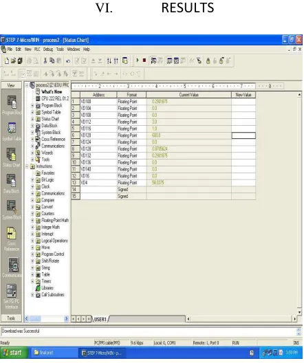
SCADA STRUCTURE OF PROCESS2VI.
RESULTS
FIGURE 6
:
RESULT OF PID PARAMETER➢ GRAPH:
[image:5.612.60.268.167.325.2]FIGURE 7
:
RESPONSE OF PID ACTION [image:5.612.41.262.369.633.2]International Journal of Emerging Technology and Advanced Engineering
Website: www.ijetae.com (ISSN 2250-2459, ISO 9001:2008 Certified Journal, Volume 8, Issue 3, March 2018)International Journal of Emerging Technology and Advanced Engineering
Website: www.ijetae.com (ISSN 2250-2459, ISO 9001:2008 Certified Journal, Volume 8, Issue 3, March 2018)300
VII.
C
ONCLUSIONThere are thousands of SCADA system installed And they can be completely different from each other, in term of their structures but they all have common element and a common purpose to supervise control and collect data.
By competition of paper, just conclude that with changing of kp and Ti values,9t’s found different respose of the system. With kp=3 and Ti=6000 .it should be done with PID tunning for tempearature.
➢ It should study the development of the project schee to understand fundamnetal automation.
➢ It should study SCADA for interfacing with PLC.
By interfacing with two PLCs, we controlled both processes simultanously through SCADA screen. Which is very easier for process engineer to visulize the process. Also, if any fault occurs process enginner received SMS through the GSM modem.
References
[1] Multidisciplinary Journal of research in Engineering and Technology.‖PLC SCADA based distribution monitoring and control‖.Santhosh B.Belekar.
[2] ―Automation based power transmission control Station using PLC and SCADA‖ Assistant Professor, Department Of Eee, Jay Shriram Group Of Institution
[3] https://www.engineersgarage.com/
[4] ―Data Acquisition System Using Programmable Logic Controller‖ J.G. Joshi
[5] K. Gowri Shankar, ―Control of Boiler Operation using PLC– SCADA‖ Proceedings of the International Multi Conference of Engineers and Computer Scientists 2008
Multidisciplinary Journal of research in Engineering and Technology.‖PLC SCADA based distribution monitoring and control‖.Santhosh B.Belekar.
[6] Mu ltidisciplinary Journal of research in Engineering and Technology.‖PLC SCADA based distribution monitoring and control‖.Santhosh B.Belekar.
[7] Burali Y. N. ―PLC Based Industrial Crane Automation
Monitoring‖,International Journal of Engineerin and Science, 2012[8] ―PLC-based SCADA system for oil storage and Application.‖ by Wang xibin North china institute of aerospace engineering LangFang, China .