International Journal of Emerging Technology and Advanced Engineering
Website: www.ijetae.com (ISSN 2250-2459, ISO 9001:2008 Certified Journal, Volume 7, Issue 11, November 2017)
126
FPGA with DTMF as Speed Controller of Induction Motor
Mukesh Payak
1, S. R. Kumbhar
2, Y. K. Vijay
31,3
Department of Electronics, Vivekananda Global University, Jaipur, Rajasthan, India
2Department of Electronics, Willingdon College, Sangli, Maharashtra, India
Abstract— To control the gain of inverter different combinations are used with different firing schemes but presently more emphasis is given on the simulation of different pulse width modulation techniques. For proper performance inverter gain is changed and its representation is presented in different PWM techniques. However, to get the better performance of the electric machine the source should contain minimum harmonics as well as distortion. In most of the designed drives, implementation of drive hardware is major problem. To resolve this problem PWM is employed which controls the gain of inverter as well as desired voltage control.
The advanced versions of microprocessors, PC, microcontrollers, PLC’s and fast switching power semiconductor devices have opened a new possibility in the power systems. This may use the algorithms and real time analysis for the optimized response. Simulation gives performance of system without the actual circuit design.
The article gives the brief information of speed control design with DTMF. The general schematic representation of the drive in the hardware and its software requirements are given. The DTMF control technique is presented. The performance and calibration of the system is also presented.
Keywords— DTMF, FPGA, Induction motor drive, PWM MOSFET Inverter drive.
I. INTRODUCTION
For general and small applications single phase induction machines prominently used in day to day applications along with Data Acquisition System[1]. The single phase microprocessor and computer control of induction motor implemented by various researchers [2-4]. Online monitoring and parameter estimation of induction motor has proposed by Uplane and et.al [1], while harmonic reduction schemes are represented by Krishnamoorty and et.al for power control drives [5,6]. May authors also implemented the various sinusoidal pulse width modulation (SPWM) schemes [7-9]. The main idea of this research article is to control the gating pulses of an AC motor drive by wireless communication using dual tone multi-frequency decoder (DTMF) technique which is implemented by an field programmable gate arrays (FPGA)[10- 20].
In case of DTMF technique, every key is having a unique tone, which is decided by combination of keypad„s column frequency and row frequency. The DTMF decoder splits the frequencies and then it converts the frequencies in to binary values. Hence, the induction motor is controlled by pressing the different keys from the users mobile unit. The control of drive is still made easier by the use of software in the control technique. The proper design and implementation of the hardware is possible with simulation technique. This will reduce the trial and error method of hardware construction
In receiver section the mobile phone is interfaced with DTMF decoder, the decoder detects the signal and then the decoded information is transferred to the Microcontroller unit. The controller unit controls induction motor with the help of control circuit using the PWM firing pulses. The mobile can be used to interface DTMF decoder. This detects the signal and transfer to the controller, the controller unit controls induction motor with the help of control circuit using the PWM firing pulses.
The system is designed around the FPGA which is commonly used in embedded applications for computing and smart decision-making capabilities to machines, products, and processes [21-33]. FPGA is capable to interact with number of automated systems. The MicroC5 software, is used for debugging the source code of FPGA and simulated [34-39]. The simulation helps to build the circuit and avoids the delay and efforts of the human.
II. SYSTEM DESGN
International Journal of Emerging Technology and Advanced Engineering
Website: www.ijetae.com (ISSN 2250-2459, ISO 9001:2008 Certified Journal, Volume 7, Issue 11, November 2017)
127
[image:2.612.55.241.142.363.2]
Figure. 1. Block diagram of the designed system
The initial trend of growth of control technique was less but the present rate is very large due to the development of modular and compact automated devices using the controller technique and the software simulation implementation in the control strategy. The feedback control using the DTMF control is used for the present system. Due to the feedback system the corrective action is also implemented in the present system. The simulation made the system design easier and its implementation with easier testing conditions. The FPGA is used to generate various types of PWM pulses for driving the gate of the inverter MOSFET.
System design consists of FPGA, DTMF, antenna, mobile unit in auto answer mode, signal conditioning circuits, Signal driver and amplifier circuits. Power supply, etc. as shown in Figure 1. The explanation of the circuit is given block wise in the following sections.
A. Inverter module
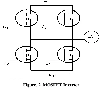
[image:2.612.354.528.146.303.2]The inverter model is designed using MOSFETs to control the induction motor. It forms the bridge of four MOSFETs which are controlled by the PWM signal generated using FPGA. PWM signal width decides the conduction of MOSFET as well as power of drive varies which controls the speed. The width of the pulse is controlled by using the software through FPGA. Figure 2 shows inverter module.
Figure. 2 MOSFET Inverter
The capacitor helps to bypass the transient current generated during the switching of PWM through inverter. This control provides power the drive. This supplied power controls the speed of drive. According to the width of firing pulse inverter MOSFETS fires and conduction of MOSFETs takes place hence as per the firing, the power is given to the system and proportional power is supplied to the drive. The Figure 3 shows the implementation of MOSFET based inverter control module.
Rectifier O/P
Figure. 3 MOSFET Based Inverter Control
The power supplied to the MOSFET based inverter through the power rectifier KBP 2510. This gives DC voltage from the AC mains. The high voltage capacitor banks are connected across the inverter which helps in rectifying and provides the bypass path to the AC. The snubber circuit consisting of inductor transistor, diode is used in series with the load to avoid the surge pulses generated during the firing of the inverter. The buffer amplifier is used to increase the signal strength of firing of the inverter. The isolator MCT2E is used for isolation purpose. Seven PWM signal is shown in the Figure 4 is used for firing is used for firing of inverter.
Antenna DTMF
Signal conditioning
Circuits
FPGA based drive
Driver circuit
Inverter
M
AC Supply Single phase
Power Rectifier
MOSFET Inverter Gate control
Signal
Capacitor banks FPGA Control
[image:2.612.326.562.417.535.2]International Journal of Emerging Technology and Advanced Engineering
Website: www.ijetae.com (ISSN 2250-2459, ISO 9001:2008 Certified Journal, Volume 7, Issue 11, November 2017)
[image:3.612.50.288.134.266.2]128 Figure. 4 PWM pulses used for firing of MOSFET
B. DTMF Control
Voice frequency signals are used in the telephone system in which the signal passing through the telephonic line. It has different tone signals represents sixteen different digits and symbols. The combination of lower group and higher group frequencies forms the single tone as output.
The DTMF may be used in two ways: Pulse dialing and Tone dialing
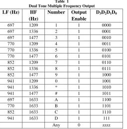
[image:3.612.44.299.464.722.2]In pulse dial the different pulses are produced and the timing to dial digit is not same as well as it takes longer time for dialing the higher digit. In case of the touch tone method, the row and column gives the frequency over which the data is presented. The time required for dialing any digit remains same. The mixing of two frequencies give the desired data as shown in the Table1.
Table 1
Dual Tone Multiple Frequency Output
LF (Hz) HF
(Hz)
Number Output Enable
D3D2D1D0
697 1209 1 1 0000
697 1336 2 1 0001
697 1477 3 1 0010
770 1209 4 1 0011
770 1336 5 1 0100
770 1477 6 1 0101
852 1209 7 1 0110
852 1336 8 1 0111
852 1477 9 1 1000
941 1209 0 1 1001
941 1336 * 1 1010
941 1477 # 1 1011
697 1633 A 1 1100
770 1633 B 1 1101
852 1633 C 1 1110
941 1633 D 1 111
Any 0 zzzz
The IC 8870 is used in the circuit for the remote operation. The remote operations are performed by using the DTMF control. Various other parameters are controlled through the DTMF circuit. The different addresses are used for controlling the different parameters. 00 address is used for the line voltage parameter 01, 02 are used for ON, OFF status while 03 address controls manages the status of the motor. In the similar manner speed, current, voltage and PWM generation parameters are managed by the various addresses. The decoding action is carried by the decoder presented in the Table 2.
Table 2 Decoder Action Performed
Number pressed by user
O/P of Decoder Action performed
0 00 x 0 00000000 AC signal check 1 00 x 1, 00000001 ON
2 0 x 02, 00000010 OFF
3 0 x 03, 00000011 Status of motor 4 0 x 04, 00000100 Speed check 5 0 x 05, 00000101 Current check 6 0 x 06, 00000110 Voltage Check 7 0 x 07, 00000111 PWM generation
III. SOFTWARE DEVELOPMENT
International Journal of Emerging Technology and Advanced Engineering
Website: www.ijetae.com (ISSN 2250-2459, ISO 9001:2008 Certified Journal, Volume 7, Issue 11, November 2017)
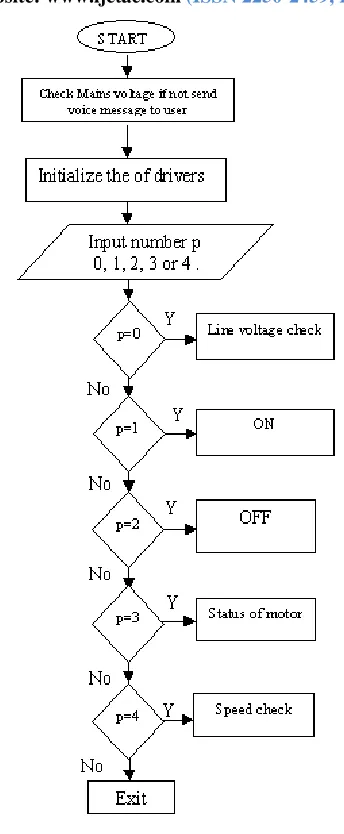
[image:4.612.80.252.131.548.2]129 Figure. 5 Flow chart of the main routine
IV. DESIGNED SYSTEM CALLIBERATION
In order to read the correct parameter data, system must be calibrated with the standard system and required corrections must be made before the data is taken for the process of operation, because, while sensing instrumental, human or environmental error may occur. Therefore, it is necessary to have a accurate reading instruments, precision meters and good source of supply. The calibration is carried for the all the measuring parameters and they are presented as –
A.Speed Calibration
To measure the speed, the disc is connected to the shaft of the motor and a small hole is drilled at its periphery. The opto-coupler has placed on the shaft and the circular disk rotates between the two ends of the coupler. Opto-coupler gives two pulses per revolution is plot of speed voltage measurement characteristics. Graph shows some irregular variation at the initial stage and then follows the linear characteristics. This non-linearity is overcome by use of software changes are applied in comparison with the standard values and new correct value is generated.
Correct speed is represented in the figure 6(b) which is done using the software.
Figure. 6(a) Sensed and voltage characteristics of the system
[image:4.612.338.552.297.474.2] [image:4.612.332.542.487.674.2]International Journal of Emerging Technology and Advanced Engineering
Website: www.ijetae.com (ISSN 2250-2459, ISO 9001:2008 Certified Journal, Volume 7, Issue 11, November 2017)
130
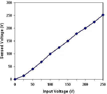
B.Voltage Calibration
Line input voltage and measured voltage form the designed circuit presented in the graphical form shown in Figure 7(a). Some error is observed n the graphical form n terms of linearity which can be corrected and the final format is presented as shown in Figure 7(b). The deviation may be due to the circuit and manufacturing discrepancies and corrected representation has linear characteristics
Figure. 7(a) Input line voltage and system detected voltage
Figure. 7(b) Corrected voltage graphical presentation
C.Current Calibration
For the current measurement simple technique is used. This technique consists of the shunt wire in series with the supply and across the shunt wire or resistance, step down transformer coil connection produces the desired voltage is proportional voltage corresponding to the input current shown as per Figure 8(a). If some difference generates in the input and output voltage output current then the correction is necessary. This can be done by the use of correction using computer. Such characteristics graphical presentation is shown in Figure 8(b).
Figure. 8(a) Graphical presentation of input and detected current.
[image:5.612.62.276.240.428.2] [image:5.612.341.544.275.442.2] [image:5.612.54.282.458.640.2] [image:5.612.336.549.465.642.2]International Journal of Emerging Technology and Advanced Engineering
Website: www.ijetae.com (ISSN 2250-2459, ISO 9001:2008 Certified Journal, Volume 7, Issue 11, November 2017)
131
V. SPEED EFFICIENCY CHARACTERISTCS
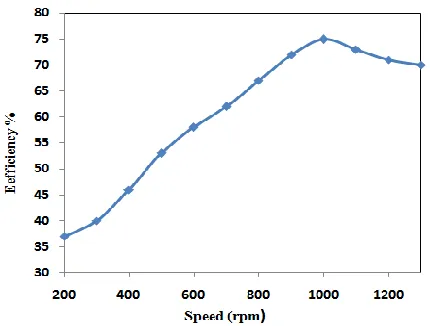
[image:6.612.61.276.253.416.2]Figure. 9 shows the speed-efficiency characteristic for seven PWM. It is observed that there is increase in efficiency with increase in speed till 1000 rpm, however beyond that the efficiency retards. This happens due to the mechanical and electrical losses in the machine. The heating loss also plays important role beyond 1000 rpm. Therefore if we compare this system with the standard drives the results are in the acceptable range.
Figure. 9 Speed efficiency characteristics
VI. CONCLUSION
The FPGA based DTMF control of the drive is possible and to control the speed the gain of the inverter driver is controlled by using the requisite PWM scheme. The DTMF helps to control the various parameters from remote place. The calibration of the system puts into the corrective mode. The system efficiency is also within the comparable limit. Hence, the desired system is helpful in many industrial control applications from the remote places.
REFERENCES
[1] M. D. Uplane, S. R. Kumbhar, M. S. Chavan, M. S. Gaikwad, Data acquisition system for simulation and online parameter estimation of induction motor using computer, J. IETE, New Delhi, Vol. 41 pp. 23-28, 2000.
[2] Lesan S., Shepherd W., “Control of Wound Rotor Induction Motor with Rotor Impedance”, IEEE, Toronto, Canada, Oct.1993, pp. 2215 – 2221.
[3] B. K. Bose, “Adjustable Speed AC drives, A technology status review”, Proc. IEEE, Vol. 70, No. 2, pp 116 - 135, Feb.1984. [4] Davey K. R., Analytic Analysis of Single and Three Phase Induction
Motors, American Electromechanics, 1998, pp.150-163.
[5] Young S., Kang G., Simulation of New Lateral Trench IGBT Employing Effective Diverter For Improving Latch Up Characteristics, Microelectronics, Vol. 32, 2001, pp. 749-753.
[6] K.A. Krishanamoorthy, G. K. Dubey and G.N. Ravankar, Converter Control with selective reduction of Line harmonics, Proc. IEEE, Vol 125,No.2, pp. 142-145,1978
[7] Soni A., Agnihotri G., Ganga A., Simulation of Protective Schemes of High Voltage Utility Motors, International Conf. on Power Transients-IPST 2002, New Oreans, USA, pp. 1-6.
[8] M. G. Ioannides, Design and implementation of PLC based monitoring control system for induction motor, IEEE Trans. Energy Convers. ,vol. 19, no. 3, pp. 469-476, Sep. 2004.
[9] Cho. Y. H., Choi Y. I., Kim H. S., Lee B. M., Han M. K., Parameter Estimation for the Static and Dynamic Model of IGBT, Proc., International Symposium on Electronics, London, May-1996, pp. 77-85.
[10] Okoli F.I, Onubogu J.O, Okezie C.C, Okorogu V.N, The Simulation of the Control of an Industrial Mixer using PLC, International Journal of Inventive Engineering and Sciences (IJIES) ISSN: 2319– 9598, Volume-1, Issue-2, January 2013,pp 2-5.
[11] Mukesh Payak and S. R. Kumbhar , Development of FPGA Based Wireless Single Phase Induction Drive, International Journal of Control Theory and Applications, , 9(17) 2016, pp. 8533-8540. [12] S. K. Rathod. M. D. Uplane, P. K. Gaikwad, S. R. Kumbhar, FPGA
based controlled Inverter motor drive, International Journal of Innovative Research In Science, Engineering and Technology, ISSN(Online): 2319-8753 ISSN (Print): 2347-6710, Vol. 6, Issue 7, July 2017, pp. 13714-13720.
[13] S. R. Kumbhar, International Journal of Latest Technology in Engineering, Management & Applied Science, Volume VI, Issue VI, June 2017 | ISSN 2278-2540, pp. 141-146
[14] Mukesh Payak, Y.K.Vijay and S. R. Kumbhar, Fault Detection of Single Phase Induction Drive Motor usol-10, No. 6, 2017, pp 243-150.
[15] B. N. Jamadar, S. R. Kumbhar, P. Joshi, S. Jagadale, D. S. Sutrawe, PIC based Speed Control of Three phase Induction moot Vis Single Phase, DAV International Journal of Science, Vol.2, Issue 1, Jan 2 2013 PP. 7-14
[16] V. R. Patil, S. R. Kumbhar, Design and Monitoring of Wireless PIC Microcontroller based Three phase Induction Drive, Special Issue of Journal of Science Information, ISSN 2229-5836, 2012, PP147-150. [17] S. R. Kumbhar, A. P. Ghatule, M. D. Uplane, Design of single phase induction motor drive and its fault detection using personal computer, International journal of research in computer Science and information technology, ISSN: 2319-5010, Vol. 1, Issue 1, 2012, pp 33-37.
[18] S. R. Kumbhar, Dr. Arjun P. Ghatule and Dr. Mahadev D. Uplane, Design of Remote Place ON-OFF Controlled Data Acquisition System for Induction Motor Drive using PIC Microcontroller, International Journal of Information Systems, ISSN : 2229 – 5429, Vol. III, Issue I, June 2012, pp. 1-5.
[19] S. R. kumbhar, B. N. Jamadar, D. V. Sutrave, PIC Microcontroller Based Speed Control of Three phase Induction Motor Using Single Phase Supply, International journal of Research in Computer Science and Information Technology, ISSN: 2319-5010, Vol.-1, Issue 1(A), Feb. 2013, pp. 37-43.
International Journal of Emerging Technology and Advanced Engineering
Website: www.ijetae.com (ISSN 2250-2459, ISO 9001:2008 Certified Journal, Volume 7, Issue 11, November 2017)
132 [21] S. R. Kumbhar and A. P. Ghatule, Microcontroller based Controlled
irrigation system for plantation, International Multi-conference of Engineers and Computer Scientists, Hongkong, ISBN 978-988-19251-8-3, 15th March 2013
[22] T. S. Dalvi, S. R. Kumbhar and A. P Ghatule, Cloud Computing in Indian Agriculture with special reference to Sangli District, International journal of Research in Computer Science and Information Technology, ISSN: 2319-5010, Vol.-2, Issue 2(A), March 2014, pp. 20-23
[23] S. K Rathod and S. R. Kumbhar, Single to Three phase PLC based external voltage control induction motor drive, International journal of Research in Computer Science and Information Technology, ISSN: 2319-5010, Vol.-2, Issue 2(A), March 2014, pp. 106-110 [24] S. S. Kumbhar and S. R. Kumbhar, Single phase multidrive control
systemusing PIC microcontroller, International journal of Research in Computer Science and Information Technology, ISSN: 2319-5010, Vol.-2, Issue 2(A), March 2014, pp. 181-184
[25] S. R. Kumbhar and A. P. Ghatule, Operators use in edge detection and determination of Actual threshold values, International journal of Research in Computer Science and Information Technology, ISSN: 2319-5010, Vol.-2, Issue 1, July 2013, pp. 35-39
[26] S. R. Kumbhar, Auto Voltage compensation for Single phase iduction motor for variable load, Vidhyabharti International interdisciplinary Research Journal, ISSN 2319-4979, Vol.2, Issue 2, pp. 80-85
[27] Sutrave D. S., Jamadar B. N., Kumbhar S. R., Gavahane P. S., Design and development of control system for Three phase induction motor using PIC micrcocontrroller, third International conference on Advances in control and optimization of dynamical system, IIT Kanpur, vol. 3 part 1. pp 807-811
[28] S. R. Kumbhar, A. P. Ghatule, Mobile operated Remote control of PLC based Induction drive using DTMF, International Journal of research in Engineering and Technology, ISSN 2321-7308, eISSN 2319-1163, Volume 3, Special issue 3, 2014, pp. 280-285.
[29] T. S. Dalvi, S. R. Kumbhar, Need of Krushi Mitra Cloud model for Agriculture with special reference to Sangli District (MS), International Journal of Research in Computer Science and Information Technology, ISSN 2319-5010, Vol. 3, Issue 1, Jul, 2014, pp 27-31.
[30] S. R. Kumbhar, A. P. Ghatule, Voltage drop Compensation in long tunnel driller and online parameter estimation. International Journal of Computer Applications, ISSN 0975-8887, pp. 9 –13.
[31] S. R. Kumbhar, Design of Sunbbers for Three Phase Induction Motor Drives, , A journal of Resarch In Electronics, ISSN 2349-8226, A Special Issue, Society for Promotion of Excellence in electronics Discipline (SPEED) 2015, pp. 223-225.
[32] S. R. Kumbhar, Poly phase inverter drive and its parameter estimation using PIC Microcontroller, A journal of Research In Electronics, ISSN 2349-8226, A Special Issue, Society for Promotion of Excellence in electronics Discipline (SPEED) 2015, pp. 223-225.
[33] T. S. Dalvi, S. R. Kumbhar, Cloud computing in agriculture for rural development with special reference to Sangli district, BVCON 2015 proceedings, ISBN No, 978-81-906932-6-6, pp161-163. 2015. [34] R. S. Pujari, S. R. Kumbhar, ICT and its role in rural development,
BVCON 2015 proceedings, ISBN No, 978-81-906932-6-6, pp.199-202. 2015.
[35] T. S. Dalvi, S. R. Kumbhar, The study of cloud computing challenges in Agriculture with special reference to Sangli district (MS), International Journal of computer applications, ISSN 0975-8887, pp 11 –13. 2015.
[36] S. S. Kumbhar, S. R. Kumbhar, Poly phase inverter drive and its parameter estimation using PIC Microcontroller, International Journal of recent advances in Engineering and Technology, ISSN (Online) 2347-2812, Vol. 3, Issue 8, 2015, pp. 20-23.
[37] T. S. Dalvi, S. R. Kumbhar, The present status and analytical view of willingness to adopt the Krushi Mitra Cloud in Sangli District, International Journal of recent advances in Engineering and Technology (IJRAET), ISSN (Online) 2347-2812, Vol. 3, Issue 8, 2015, pp. 24-26.
[38] Sutrave D. S., Jamadar B. N., Kumbhar S. R., Gavahane P. S., Design and development of control system for Three phase induction motor using PIC micrcocontrroller, Proceedings of Third International conference on Advances in control and optimization of dynamical system, IIT Kanpur, vol. 3 part 1. pp 807-811.