International Journal of Emerging Technology and Advanced Engineering
Website: www.ijetae.com (ISSN 2250-2459, ISO 9001:2008 Certified Journal, Volume 3, Issue 9, September 2013)
198
Design & Analysis of a surface propeller using FEM
M. Suneetha
1, R. Surendra Rao
2, V. Vishnu vardhan
3, Dr. G. Harinath Gowd
41PG Student, MITS, Madanapalle. Andhra Pradesh., INDIA
2 Assistant Professor, SKD Engineering College, GOOTY, Anantapur Dist.
3
Head of the Department, Intellectual Engineering College, Anantapur
4Professor, Department of Mechanical Engineering, MITS, Madanapalle. Andhra Pradesh., INDIA.
Abstract— Propeller design aims at achieving high propulsive efficiency at low levels of vibration and noise, usually with minimum cavitation. Achieving this aim is difficult with conventional propellers, as ships have become larger and faster propeller diameters have remained limited by draught and other factors. Surface piercing propeller offers an attractive alternative to high-speed crafts, which operate under limited draught. The performance of the vehicle depends upon the efficiency of the propeller. The geometric shape and its surface finish will decide the efficiency of the propeller. The material used is carbon UD and aluminium. The present research basically deals with the modeling and Analysis of the propeller using composite material of a marine vehicle having low draft. A propeller is complex 3D model geometry. CATIA modeling software is used for generating the blade model and tool path on the computer. Sectional data, pitch angle of the propeller are the inputs for the development of propeller model. Finite element analysis was carried out using ABAQUS. The propeller model developed in CATIA is converted in to IGES file and then imported to HYPERMESH for developing fine mesh of the model. As a part of the analysis static structural testing was conducted by varying material properties in pre-processing stage.
Keywords— Surface Propeller, CATIA, HYPERMESH, ABACUS.
I. INTRODUCTION
A propeller is a type of fan that transmits power by converting rotational motion into thrust. A pressure difference is produced between the forward and rear surfaces of the airfoil-shaped blade, and air or water is accelerated behind the blade. Propeller dynamics can be modeled by both Bernoulli's principle and law. A propeller is the most common propulsion on ships, imparting momentum to a fluid which causes a force to act on the ship. Three, four, are most common in marine propellers, although designs which are intended to operate at reduced noise will have more blades. The blades are attached to a boss (hub), which should be as small as the needs of strength allow - with fixed pitch propellers the blades and boss are usually a single casting.
A ship needs propulsion system to move in water, so by using a thrust – producing mechanism the ship moves. There are many thrust-Producing devices called propulsors like screw propellers, pump jet, water jet etc which producing by high speed crafts, ships, pleasure crafts and torpedoes. The speed of marine vehicle depends on the choice of propulsion system. The thrust from the propeller is transmitted to move the ship through a transmission system which consists of a rotational motion generated by the main engine crank shaft, intermediate shaft and its bearings, stern tube shaft and its bearing and finally by the propeller itself.
Propellers are be classified into 1) Three Blade propeller and 2) Four Blade Propeller.
The Three blade propeller has the following characteristics:
- The manufacturing cost is lower than other types. - Are normally made up of aluminum alloy.
- Gives a good high speed performance. - The acceleration is better than other types. - Low speed handling is not much efficient.
The Four blade propeller has the following characteristics:
- The manufacturing cost is higher than 3 blade propellers.
- 4 blade propellers are normally made up of stainless steel alloys.
- Have better strength and durability.
- Gives a good low speed handling and performance. - Has a better holding power in rough seas.
- 4 blade propeller provides a better fuel economy than all the other types.
International Journal of Emerging Technology and Advanced Engineering
Website: www.ijetae.com (ISSN 2250-2459, ISO 9001:2008 Certified Journal, Volume 3, Issue 9, September 2013)
199 II. MODELING USING CATIA
It is a multi-platform CAD/CAM/CAE commercial software suite developed by the French company Dassault’s Systems and marketed worldwide by IBM. Written in the C++programming language, The software was created in the late 1970s and early 1980s to develop Dassault'sMirage fighter jet, and then was adopted in the aerospace, automotive, shipbuilding, and other industries.
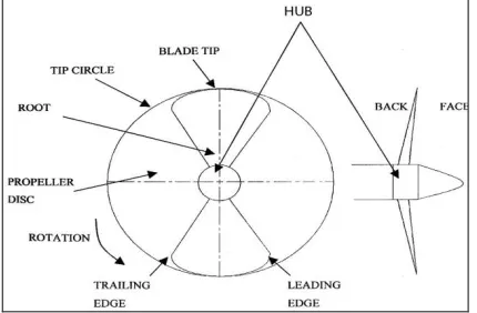
A propeller consists of a number of identical blades on a boss. The propeller is usually fitted at the aft end of the ship. The surface of a propeller blade, which faces aft is called its Face, the opposite surface being the Back of the blade. The junction of the blade to the boss is the blade root and the extremity of the blade (the point farthest from the center of the propeller) is the blade tip. The blades of a propeller; the sometimes inclined aft with respect to the axis of the rotating of the propeller; the propellers are then said to have rake. The inclination of the propeller blade in a plane normal to the propeller axis is called skew. When the propeller is rotating so as to cause the ship to move forward, the front edge (with respect to the motion) is called the leading edge of the propeller blade propeller blade, while the rear edge is called the trailing. The diameter of the circle traced out by the blade tips when the propeller is turning is called the propeller diameter (D).
[image:2.612.325.569.434.625.2]CATIA allows for creation of complete three-dimensional models of parts. The part model can be used to (i) produce fully-dimensioned engineering drawings for manufacturing the part (ii) Generate the tool path (iii) Verify tool path (iv) Generate NC part program for NC machines (v) Generates inputs for analytical processes such as Finite element analysis. These components are modeled by using the geometric entities like Points, Curves, surface, etc. The geometry of the propeller is shown in Figure 1.
Figure 1. Geometry of the propeller
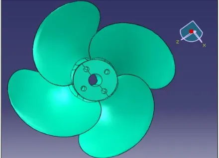
The 3D model developed using CATIA is shown in FIgure 2.
Figure 2. Model of the Surface propeller
HYPERMESH is a high performance finite element pre processor that provides highly interactive and visual environment to analyze product design performance. With the broadest of direct interfaces to commercial CAD and CAE systems, mesh provides a proven consistent analysis platform for the entire enterprise
.
The meshed surface is shown in figure 3. [image:2.612.62.277.524.665.2]International Journal of Emerging Technology and Advanced Engineering
Website: www.ijetae.com (ISSN 2250-2459, ISO 9001:2008 Certified Journal, Volume 3, Issue 9, September 2013)
200 III. INTRODUCTION TO ABACUS
The ABAQUS is an engineering simulation software. It develops general-purpose finite element analysis and computational software. While ABAQUS has developed a range of computer-aided engineering (CAE) products. ABAQUS Mechanical and ABAQUS Multi physics software are non exportable analysis tools incorporating pre-processing (geometry creation, meshing), solver and post-processing modules in a graphical user interface. These are general-purpose finite element modeling packages for numerically solving mechanical problems, including static/dynamic structural analysis (both linear and non-linear), heat transfer and fluid problems, as well as acoustic and electro-magnetic problems.
Steps in ABAQUS
To solve any problem in ABAQUS it mainly follows the following steps. These are common steps to all problems except material properties and type of analysis used.
1) Preliminary decisions
a. Analysis type b. Model c. Element type
2) Pre processing
a. Material
b. Create or import the model geometry
c.
Mesh the geometry3) Solution
a. Apply loads b. Solve
4) Post processing
a. Review results
b. Check the validity of the solution
Procedure to Analyze the Propeller:
1. Importing File to ABAQUS:
The model created in CATIA is imported into ABAQUS using the IGES/IGS file. By using the following procedure file can be imported:
[image:3.612.334.554.122.281.2]STEP I : Select file option and import using part format. STEP II : Browse the file from the selected location and open it.
Figure 4. Propeller geometry imported to ABAQUS 2. Preprocessor:
This is the first stage for Abaqus of propeller.
Select the Element type for the imported propeller.
Add the Element type required for the propeller i.e HEXA and PENTA
After defining the element type next step is to give real constants.
Select the real constant and add the thickness to it.
3. Material Properties:
Select the material module option and select material manager.
After that we have to define the material properties.
Select section manager and call material properties in this section.
Assign the section by picking the part.
4. Load Step:
Select Step module
Step Manager> Create> Load Step>
Select STATIC,
5. Loading:
Select Load Module
Load Manager>Create>Mechanical> Pressure
International Journal of Emerging Technology and Advanced Engineering
Website: www.ijetae.com (ISSN 2250-2459, ISO 9001:2008 Certified Journal, Volume 3, Issue 9, September 2013)
[image:4.612.50.290.121.270.2]201
Figure 5. Boundary Conditions Applied On the Nodes
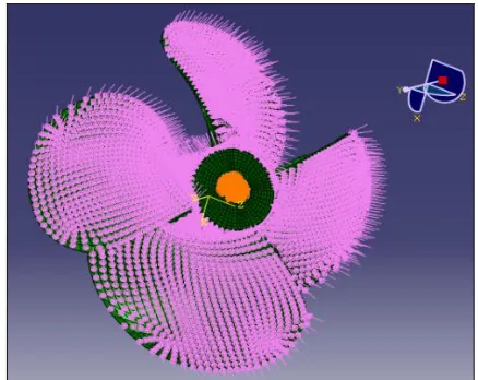
[image:4.612.333.551.123.268.2]The pressure load is applied on the blade as shown in the figure 6.
Figure 6. Pressure Loads Applied On the Propeller Blades 6. Solving
This is the second stage in the analysis of propeller. In this we will solve to get the deformed shape and stresses that are applied on the propeller.
IV. RESULTS
After Post Processing theoverlap of both deformed and un-deformed shapes are shown in figure 7.
Figure 7. Deformation of the Propeller
The analysis is carried out for two different materials and the results are compared.
Material Aluminium
Select Field Output>Step/Frame>Step Name (Pressure Load Step
Index as 1> say Ok
[image:4.612.332.560.315.667.2] Select Primary Variable as U(Spatial displacement at nodes)>Magnitude
Figure 8. Displacement Vector Sum
Select Primary Variable as U(Spatial displacement at nodes)>U22( Y-direction)
[image:4.612.58.277.322.496.2]International Journal of Emerging Technology and Advanced Engineering
Website: www.ijetae.com (ISSN 2250-2459, ISO 9001:2008 Certified Journal, Volume 3, Issue 9, September 2013)
202
[image:5.612.54.283.93.630.2] Select Primary Variable as U(Spatial displacement at nodes)>U33(Z-direction)
Figure 10. Displacement in Z-Direction
[image:5.612.336.553.122.273.2] Select Primary Variable as S(Stress component at integration points)>S(VonMisesStress)
Figure 11. Von Mises Stress
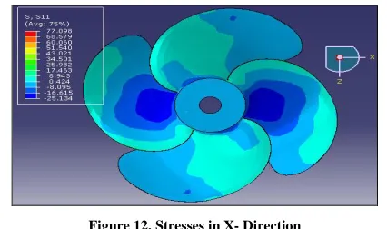
[image:5.612.61.281.131.300.2] Select Primary Variable as S(Stress component at integration points)>S11( X-direction)
Figure 12. Stresses in X- Direction
[image:5.612.61.274.496.622.2] Select Primary Variable as S(Stress component at integration points)>S22( Y-direction)
Figure 13. Stresses in Y-Direction
Select Primary Variable as S(Stress component at integration points)>S33( Z-direction)
Figure 14. Stresses in Z-Direction Composite Material
Select Field Output>Step/Frame>Step Name (Pressure Load Step
Index as 1> say Ok
Select Primary Variable as U(Spatial displacement at nodes)>Magnitude
[image:5.612.337.552.516.652.2]International Journal of Emerging Technology and Advanced Engineering
Website: www.ijetae.com (ISSN 2250-2459, ISO 9001:2008 Certified Journal, Volume 3, Issue 9, September 2013)
203
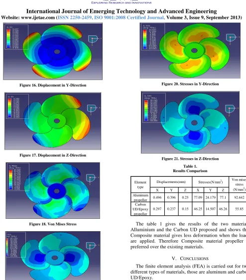
Figure 16. Displacement in Y-Direction
Figure 17. Displacement in Z-Direction
Figure 18. Von Mises Stress
[image:6.612.62.556.76.639.2]Figure 19. Stresses in X-Direction
[image:6.612.327.560.92.523.2]Figure 20. Stresses in Y-Direction
Figure 21. Stresses in Z-Direction Table 1.
Results Comparison
X Y Z X Y Z
Aluminum
propeller 0.496 0.396 0.25 77.09 24.179 77.1 92.642 Carbon
UD/Epoxy propeller
0.297 0.237 0.15 46.25 14.507 46.26 55.85 Element
type
Displacements(mm) Stresses(N/mm2) Von mises stress (N/mm2)
The table 1 gives the results of the two materials Alluminium and the Carbon UD proposed and shows that Composite material gives less deformation when the loads are applied. Therefore Composite material propeller is preferred over the existing materials.
V. CONCLUSIONS
The finite element analysis (FEA) is carried out for two different types of materials, those are aluminum and carbon UD/Epoxy.
International Journal of Emerging Technology and Advanced Engineering
Website: www.ijetae.com (ISSN 2250-2459, ISO 9001:2008 Certified Journal, Volume 3, Issue 9, September 2013)
204 1.The von-mises stress acting on the propeller produced
from aluminum is 92.642 N/mm2, corresponding deformation is 0.496mm.
2.The von-mises stress acting on the propeller produced from carbon UD/epoxy is 55.585 N/mm2 and is observed that the value is within the allowable stress limit. Deformation produced for carbon UD/epoxy material is 0.297mm.
3.Finally it is concluded that carbon UD/epoxy material can give a better performance with respect to static analysis.
REFERENCES
[1] ABAQUS, ABAQUS Version 6.5 Documentation. ABAQUS, Inc., 1080 Main Street, Pawtucket, RI 02860; 2005.
[2] Lee, Y., Lin, C., 2004. Optimized design of composite propeller. Mechanics of Advanced Materials and Structures 11, 17–30 [3] Chen, B., Neely, S., Michael, T., Gowing, S., Szwerc, R., Buchler,
D., Schult, R., 2006. Design, fabrication and testing of pitch-adapting (flexible) composite propellers. In: The SNAME Propellers/Shafting Symposium ’06. Virginia Beach, VA.
[4] Grandin Jr K. Fundmentals of the "Finite element method. New York: Macmillan, 1986.
[5] Lübke LO. Numerical simulation of the flow around the propelled KCS. In: CFDWS05, Tokyo, Japan; 2005.
[6] Lerbs, H.W., 1925. Moderately loaded propellers with a finite number of blades and an arbitrary distribution of circulation. Transaction of SNAME 60.