International Journal of Emerging Technology and Advanced Engineering
Website: www.ijetae.com (ISSN 2250-2459,ISO 9001:2008 Certified Journal, Volume 5, Issue 11, November 2015)
172
Synchronous Rotating Frame Based Controller for Three Phase
Shunt Active Power Filter
Dr. Rama Rao P.V.V.
1, B. Kali Prasanna
2, S. Veerababu
31Professor & HOD, 2&3Assistant Professor, Department of EEE, Shri Vishnu Engineering College for Women, Bhimavaram,
India
Abstract— The large scale use of power electronics equipment has led to increase in harmonics in the power system, which results in power factor reduction, decrease in
efficiency, power system voltage fluctuations and
communication interfaces.
The SAPF will suppress the harmonic content present in the line and make the current waveform sinusoidal. The most efficient ways of generating reference current are p-q theory and synchronous reference frame theory (SRF).
In this paper, the SRF strategy is used to generate current reference for compensation of the three-phase shunt active power filter (SAPF) currents under distorted and/or imbalanced source voltages in steady state. The simulation results have been done by using MATLAB/SIMULINK.
Keywords— Shunt active filter, Harmonics, STATCOM, THD, Voltage Source Inverter
I. INTRODUCTION
In modern electrical distribution systems there has been a sudden increase of single phase and three-phase non-linear loads. These non-non-linear loads employ solid state power conversion and draw non-sinusoidal currents from AC mains and cause harmonics and reactive power burden, and excessive neutral currents that result in pollution of power systems. Shunt active filters based on current controlled PWM converters are seen as viable solution. The techniques that are used to generate desired compensating current are based on instantaneous extraction of compensating commands from the distorted currents or voltage signals in time domain. Time domain compensation has fast response, easy implementation and less computation burden compared to frequency domain.
Most of the active power filter topologies use voltage source converters, which have a voltage source at the dc bus, usually a capacitor, as an energy storage device. Voltage source converters are preferred over current source converter because it is higher in efficiency and lower initial cost than the current source converters.
The higher-order harmonics can be eliminated by using converters without increasing individual converter switching rates.
There are different control strategies being used for the calculation of reference currents in active power filter namely Instantaneous Reactive Power Theory (p-q theory), Unity Power Factor method, One Cycle Control, Fast Fourier Technique etc. Here, SRF theory is used to extract the three-phase reference currents (ica*, icb*, icc*) used by the active power filters
II.SRFCONTROL METHODS
The reference currents are estimated for controller design which is based on p-q, d-q theories. The description of the conventional p-q and d-q (SRF) methods are presented, and the SRF based controller is modeled.
A) Instantaneous Active Power Theory (p-q Theory)
The instantaneous active, reactive power method, proposed by Akagi [4], for calculating the reference compensation currents required to inject into the network at the connected point of the nonlinear load. It remains one of the most popular SAPF control schemes. Network at the connected point of the nonlinear load. Since then, the theory has inspired many works dealing with active power filter compensation strategies. One of the peculiar features of a shunt APF is that it can be designed without active energy source units, such as batteries, or in other forms in its compensation mechanism. In other words, an ideal APF does not consume any average power supplied by source [5].
International Journal of Emerging Technology and Advanced Engineering
Website: www.ijetae.com (ISSN 2250-2459,ISO 9001:2008 Certified Journal, Volume 5, Issue 11, November 2015)
173
Figure 1: Power Components in P-Q theory
B) Synchronous Reference Frame Method (d-q Method)
A synchronous reference frame method for obtaining the load currents at the fundamental frequency, which will be the desired source currents. The APF reference compensation currents are then determined by subtracting the fundamental components from the load currents.
Another important characteristic of this theory is the simplicity of the calculations, which involves only algebraic calculation. The basic structure of SRF controller consists of direct (d-q) and inverse (d-q)-1 park transformations below. These can useful for the evaluation
of
a specific harmonic component of the input signals
One of the main differences of this method from p-q theory is that the d-q method requires the determination of the angular position of the synchronous reference of the source voltages; for this a PLL algorithm is used. After the transformation of load currents into the synchronous reference, a low-pass or high-pass filter is using to separate the fundamental and harmonic components. Finally, the reference currents are transformed to the three phase reference using the inverse synchronous transform. [5]
III. SHUNT ACTIVE POWER FILTER(APF)
[image:2.612.62.268.404.472.2]Shunt active filters mainly consist of two main blocks, The PWM converter (power processing) and the active filter controller (signal processing)
Figure 2: SAPF Basic compensation principle
A) Principle of operation:
The basic compensation principle of a shunt active power filter is controlled to drawn or supply a compensating current ic from or to the utility, so that it cancels current harmonics on the AC side, and makes the source current in phase with the source voltage.. So, SAPF operates mainly in two modes
1) STATCOM mode of operation:
Static Synchronous Compensator (STATCOM) is a part of the Flexible Alternating Current Transmission systems (FACTS) device family.
STATCOMs can be used for Voltage regulation at the receiver end of ac transmission lines, thus replacing banks of shunt capacitors. STATCOMs are commonly used for dynamic power factor correction (i.e., dynamic reactive power compensation) in industrial plants operating with large random peaks of reactive power demand.
2) Harmonic Compensation:
International Journal of Emerging Technology and Advanced Engineering
Website: www.ijetae.com (ISSN 2250-2459,ISO 9001:2008 Certified Journal, Volume 5, Issue 11, November 2015)
174
IV. SYNCHRONOUS REFERENCE FRAME THEORY
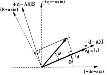
Reference frame transformation refers to transformation from b-c to d-q-0 axes. Coordinates from a three-phase a-b-c stationery coordinate system to the d-q-0 rotating coordinate system
Figure 3: Illustration of rotating reference frame concept
The voltages Vabc are transformed to d-q components such that with an added advantage of d-q theory the voltage axis is aligned in with the d-axis such that the component along the q or quadrature axis will be zero.
The same transformation applied for currents Iabc such
phase angle. Such that from figure and
From basic definitions of Active power and Reactive power
So for a given system voltage will be constant so, and .
―So, active power control indirectly means controlling of
Id component and reactive power control indirectly means
controlling of Iq component.‖
V. MATHEMATICAL MODELLING OF THE COMPENSATOR
[image:3.612.81.260.204.329.2]For the purpose of developing the controller for the compensator, mathematical modeling is proposed below. The below figure shows the compensator where VSI is connected to grid through a coupling reactor of inductance L and resistance R.
Figure 4: Schematic of SAPF Model
Where voltages generated by inverter,
are currents of inverter and are voltages of grid/source.
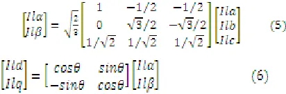
From the fig 7, Voltage equation in stationary a-b-c frame is
= … (5)
The above equation is assumed under the power system is balanced, harmonics are absent and R is small. The a-b-c frame equations can be transformed according to α-β theory.
… (6)
The α-β components transformed to d-q components
…. (7)
….. (8)
By using the equations (7), (8) the physical system which consists of converter connected to AC system is modelled. In the above equation , are PI controller outputs of respective current control loops.
A) Controller for SAPF:
The equations (3) & (4) obtained after transformation, consists of ―ω‖ term, coupled with current components such as Id, Iq. Due to this coupling term, the reference current tracking capability of controllers is not rapid enough for coupled systems.
The main objective of the controller is to improve the performance and to make controllers as independent one, a
International Journal of Emerging Technology and Advanced Engineering
Website: www.ijetae.com (ISSN 2250-2459,ISO 9001:2008 Certified Journal, Volume 5, Issue 11, November 2015)
[image:4.612.55.588.78.702.2]175
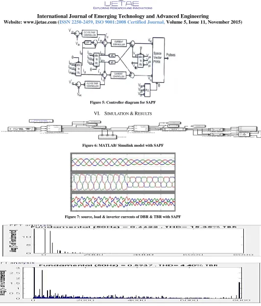
Figure 5: Controller diagram for SAPF
VI. SIMULATION &RESULTS
Figure 6: MATLAB/ Simulink model with SAPF
Figure 7: source, load & inverter currents of DBR & TBR with SAPF
International Journal of Emerging Technology and Advanced Engineering
Website: www.ijetae.com (ISSN 2250-2459,ISO 9001:2008 Certified Journal, Volume 5, Issue 11, November 2015)
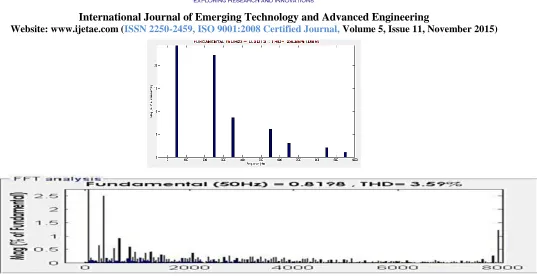
[image:5.612.52.589.94.370.2]176
Figure 9: Harmonic spectrum of DBR without & with shunt active power filter
VII. CONCLUSION
Among all other control strategies for obtaining the reference compensation currents for shunt active power filter, the SRF based controller gives better harmonic elimination and maintaining sinusoidal source currents supplying average real power to the load. This proposed controller provides real time applications relating to Digital implementation and other sophisticated controller applications. The proposed controller is designed using MATLAB/SIMULINK model and the THD obtained as according to IEEE standards i.e.…, less than 5%.
REFERENCES
[1] E.Wald F.Fuchs, Mohammad A.S.Masoum ―Power Quality in Power
Systems and Electrical Machines‖ Academic press is an imprint of Elsevier, 2008
[2] Nitin Gupta, S. P. Singh and R. C. Bansal ―A DSP Based
Performance Evaluation of Three phase Four-wire Shunt Active Filter for Harmonic Elimination, Reactive Power Compensation, Electric Power Components and Systems, Vol. 40, No. 10, pp. 1119–1148, July-2012
[3] Consalva J.Msigwa, Beda J Kundy and Bakari M.M.Mwinyiwiwa ―
Control Alagorithm for Shunt active power Filter using SRF theory Scholar waset.org/2009/14688.
[4] Rejil.c ,AnzariM and Ariun kumar.R ― Design and simulation of
Three phase shunt active power filter Using SRF
theory‖/ripublications/aeee.htm volume-3/2013
[5] P.Tripura, Y.S.Kishore Babu, Y.R.Tagore ―Space Vector Pulse
Width Modulation Schemes for Two-Level Voltage Source Inverter‖ ACEEE Int. J. on Control System and Instrumentation, Vol. 02, No. 03, October 2011.
[6] H.Akagi ―Modern active filters and traditional passive filters‖
bulletin of the polish academy of sciences technical sciences vol 54, No. 3, 2006.
[7] Poorvi M. Parmar, Prof. M.V. Makwana, ’’HARMONIC
ANALYSIS USING SHUNT ACTIVE FILTER’’, Journal of Information, Knowledge and Research in Electrical Engineering.
[8] S.Eswara Rao, Dr. B. P. Muni, JVR Vithal, SN saxena
―Development of ±500KVAR DSTATCOM for distribution utility and industrial Applications‖, corp.R&D, BHEL, hyd.
[9]―Generalised Machine theory‖ by Dr. P. S. Bimhra, Khanna
Publications.
[10] ―High power converters and AC drives‖ by binwu, IEEE press A