International Journal of Emerging Technology and Advanced Engineering
Website: www.ijetae.com (ISSN 2250-2459,ISO 9001:2008 Certified Journal, Volume 4, Issue 7, July 2014)
306
A Novel Transmit Diversity Approach for MIMO System
using Different STBC Coding Schemes
Ankit Pandit
1, Rupesh Kumar Dutta
21,2Department of Electronics and Communication, LNCT INDORE (MP)
Abstract— Multiple Input, Multiple Output (MIMO) technology is a wireless technology that uses multiple transmitters and receivers to transfer more data at the same time. In order to utilize the huge potential of multiple antenna concepts, it is necessary to resort to new transmit strategies, referred to as Space-Time Codes, which, in addition to the time and spectral domain, also use the spatial domain. This paper contains the performance analysis of Bit Error Rate (BER) in MIMO system using STBC codes. We compare OSTBC scheme with different coding schemes viz; ABBA, Jafarkhani, and Tarokh in PSK modulation. To achieve full diversity, Zero Forcing (Z-F), Minimum Mean Square Error (MMSE) equalization techniques are used. The overall performance is measured with the help of Bit Error rate.
Keywords- ABBA, BER, Jafarkhani, MIMO, MMSE, PSK, Tarokh, ZF.
I. INTRODUCTION
Wireless communication systems have traditionally used a single antenna for transmission and a single antenna for reception. These systems are known as single input single output or SISO systems. In recent years however, significant progress has been made in the area of developing systems that use multiple antennas at the transmitter and receiver to achieve better performance. Such usage can be viewed as an extension of the very popular „smart antennas‟ technology. Systems employing such technologies are known as multiple inputs multiple output or MIMO systems. WE have analysed the full diversity condition in MIMO to achieve the better BER performance.
Transmit Diversity
Transmit diversity improves the signal quality and achieves a higher SNR ratio at the receiver side; it involves transmitting data stream through multiple antennas and receiving by single antenna or more. Transmit diversity can effectively mitigate multipath fading effects as multiple antennas afford a receiver several observations of the same data stream. Each antenna will experience a different interference environment and if one antenna experienced a deep fade, then it is likely that another has a sufficient signal. Thus, transmit diversity can help improve the reliability of the data reception and data decoding as well. The most popular examples of these transmit diversity techniques include Alamouti code [1] and orthogonal codes and orthogonal codes proposed by Tarokh [2].
[image:1.595.353.505.248.344.2]Figure 1 shows the whole system for an exemplary transmits antenna system.
Figure 1: Transmit diversity
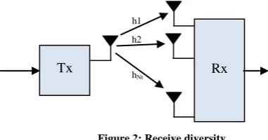
Receive Diversity
[image:1.595.316.507.451.551.2]Receive diversity are widely used in wireless communication systems; it can be achieved by receiving redundant copies of the same signal. The idea behind receive diversity is that each antenna at the receive end can observe an independent copy of the same signal. Therefore the probability that all signals are in deep fade simultaneously is significantly reduced.
Figure 2: Receive diversity
Space-Time Coding (STC) is a technique that combines coding, modulation and signal processing to achieve transmit diversity. The first STC proposed in the literature is Space-Time Trellis Code (STTC), which has a good decoding performance but decoding complexity that increases exponentially with the transmission rate. In addressing the issue of decoding complexity of STTC, Space-Time Block Code (STBC) was subsequently proposed. Alamouti [1] discovered a remarkable STBC scheme for two transmit antennas. This scheme supports linear decoding complexity for maximum-likelihood (ML) decoding, which is much simpler than the decoding of STTC. Alamouti‟s scheme is very appealing in terms of implementation simplicity. Hence it motivates a search for similar schemes for more than two transmit antennas, to achieve diversity level higher than two. As a result, Orthogonal Space-Time Block Code (O-STBC) was introduced by Tarokh [2].
Tx Rx
h 1 h 2
h
Nt
h2
Rx h1
hNt
International Journal of Emerging Technology and Advanced Engineering
Website: www.ijetae.com (ISSN 2250-2459,ISO 9001:2008 Certified Journal, Volume 4, Issue 7, July 2014)
307
O-STBC is generalizations of the Alamouti‟s scheme to arbitrary number of transmit antennas. It retains the property of having linear maximum-likelihood decoding with full transmit diversity.
In this paper we analyze the different space time coding style for transmit diversity of MIMO system and related receiving algorithms (Z-F and MMSE).
II. SPACE TIME BLOCK CODES
ABBA Code
Two Alamouti codes for two transmit antennas are used as building blocks of the ABBA code for 4 transmit antennas:
(1)
The equivalent virtual channel matrix results in:
(2) Applying a matched filter at the receiver, the non-orthogonality of the ABBA code shows up in the
Grammian matrix :
(3)
Where the channel is is gain
and is a channel dependent interference parameter:
(4)
One major limitation of the ABBA code is its loss of robustness in highly correlated channels, especially in the
case when which leads to the
collapse of all detection / decoding algorithms.
Jafarkhani Scheme
A lot of effort had been made to find orthogonal designs with highest rates in a systematic way. Therefore to reach a higher rate, one should change the structure of the orthogonal code, e.g. relaxing one of the properties of an orthogonal design. For example we can think of designing a full-diversity rate one code that does not have the property of single maximum likelihood decoding.
Increasing the order of complexity of decoding by one from separate decoding we get to pair-wise decoding; meaning that each two symbols should be detected independent of other pairs. The first such design was offered by Jafarkhani in [3] as the following matrix.
C =
(5)
Where
A = , B = (6)
The minimum rank of the A(C, E) is two for C≠E matrices. The design is called a Quasi Orthogonal Space-Time Block Code. The reason is that in the new design each column of the generator matrix is orthogonal to all the others except one, and so the name chosen Orthogonal.
Tarokh Scheme
A space–time block code is defined by a transmission matrix . The entries of the matrix are linear combinations of the variables and their conjugates. The number of transmission antennas is n and we usually use it to separate different codes from each other. For example, represents a code which utilizes two transmit antennas and is defined by:
= (7)
We assume that transmission at the baseband employs a signal constellation A with elements. At time slot 1, kb bits arrive at the encoder and select constellation
signals . Setting = for in
we arrive at a matrix C with entries linear combinations of and their conjugates. So,
while contains in-determinates C
contains specific constellation symbols (or their linear combinations) which are transmitted from n antennas for each kb bits as follows. If represents the element in the row and the ith column of C, the entries , i = 1,2,……,n are are transmitted simultaneously from transmit antennas 1,2,……,n at each time slot 1,2,……,m. So, the ith column of C represents the
transmitted symbols from the ith antenna and the row of C represents the transmitted symbols at time slot t Note that C is basically defined using , and the orthogonality of ‟s columns allows a simple decoding scheme which will be explained in the sequel. Since m time slots are used to transmit k symbols, we define the rate R of the code to be R= . For example, the rate of
International Journal of Emerging Technology and Advanced Engineering
Website: www.ijetae.com (ISSN 2250-2459,ISO 9001:2008 Certified Journal, Volume 4, Issue 7, July 2014)
308
In this work, we consider the performance of the following rate half space–time block codes:
= (8)
And
= (9)
Orthogonal STBC
An orthogonal STBC is characterized by a code matrix Gp×n where p denotes time delay or block length and n represents the number of transmit antennas. The entries of G are linear combinations of k data symbols or their conjugate, s1, s2,…,sk, , ,…… that belong to an arbitrary signal constellation. The columns of G are orthogonal to each other
= (|s1|2 + |s2|2 + ・・・+ |sk|2)In (10)
Where denotes the complex conjugate transpose of matrix A, and In is the size-n identity matrix. The code rate of G is defined as R = k/p (i.e., each codeword with block length p carries k information symbols). To motivate the developments in this manuscript, consider as an example a communication system with two transmit and one receive antennas that utilizes the orthogonal STBC. If y1 and y2 denote the received signals
at time slot 1 and time slot 2, respectively, then the received signal vector [y1 y2]
T
can be expressed as follows:
(11)
Where G2 (s1, s2) is the orthogonal
STBC, h1 and h2 denote the channel coefficients from the two transmit antennas to the receive antenna, and n1, n2 represent additive complex Gaussian noise pertinent to time slot 1 and 2, respectively. Due to the special structure of G2 (s1, s2), the received signal in (11) can be
rewritten as:
(12)
It is interesting to note that in (12) the STBC structure
is embedded in the channel matrix , while the
two data symbols appear as the elements of a 2 × 1 data input vector and the received signal at time slot 2, y2,
appears conjugated. The linearreceived signal expression in (12) is appealing as it is backward compatible with existing signal processing techniques and standards and allows, for example, the design of low complexity interference suppressing filters and channel equalizers.
Proposed Scheme
Our proposed space–time block code is defined by a Toeplitz OSTBC matrix . The entries of the matrix are linear combinations of the variables and their conjugates. Represents a code which utilizes two transmit antennas and is defined by:
(13)
III. EQUALIZATION TECHNIQUES
Zero-Forcing
Zero-Forcing (ZF) technique is the simplest MIMO detection technique, Where filtering matrix is constructed using the ZF performance based criterion. The drawback of ZF scheme is the susceptible noise enhancement and loss of diversity order due to linear filtering [4], [5]. ZF can be implemented by using the inverse of the channel matrix H to produce the estimate of transmitted vector
= r
= (Hx)
= x (14)
Where denotes the pseudo-inverse. But when the noise term is considered, the post-processing signal is given by:
= R = (Hx+n)
= x + n (15)
International Journal of Emerging Technology and Advanced Engineering
Website: www.ijetae.com (ISSN 2250-2459,ISO 9001:2008 Certified Journal, Volume 4, Issue 7, July 2014)
309
To alleviate for the noise enhancement introduced by the ZF detector, the MMSE detector was proposed, where the noise variance is considered in the construction of the filtering matrix G.
Minimum Mean Square Error
Minimum Mean Square Error (MMSE) approach alleviates the noise enhancement problem by taking into consideration the noise power when constructing the filtering matrix using the MMSE performance-base criterion. The vector estimates produced by an MMSE filtering matrix becomes
= [[(HHH + (σ2I))-1] HH] r (16)
Where σ2 is the noise variance. The added term (1/SNR = σ2, in case of unit transmit power) offers a trade-off between the residual interference and the noise enhancement. Namely, as the SNR grows large, the MMSE detector converges to the ZF detector, but at low SNR it prevents the worst Eigen values from being inverted. At low SNR, MMSE becomes Matched Filter
[(HHH + (σ2I))-1] HH≈σ2 HH (17)
At high SNR, MMSE becomes ZF:
(HHH + (σ2I))-1] HH≈ (HHH)-1 HH (18)
IV. SIMULATION RESULTS
0 5 10 15 20 25 30
10-6 10-5 10-4 10-3 10-2 10-1 100
SNRdb(dB)
B
E
R
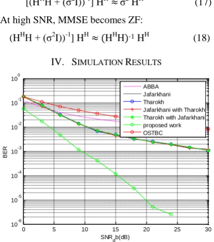
ABBA Jafarkhani Tharokh
[image:4.595.328.532.139.302.2]Jafarkhani with Tharokh Tharokh with Jafarkhani proposed work OSTBC
Figure 3: Variation in BER for different coding scheme for 4 PSK with MMSE equalizer
0 5 10 15 20 25 30
10-5 10-4 10-3 10-2 10-1 100
SNR db(dB)
B
E
R
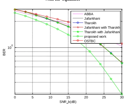
ABBA Jafarkhani Tharokh
[image:4.595.326.534.338.502.2]Jafarkhani with Tharokh Tharokh with Jafarkhani proposed work OSTBC
Figure 4: Variation in BER for different coding scheme for 4 PSK with ZF equalizer
0 5 10 15 20 25 30
10-3 10-2 10-1 100 101
SNR db(dB)
B
E
R
ABBA Jafarkhani Tharokh
[image:4.595.59.270.385.623.2]Jafarkhani with Tharokh Tharokh with Jafarkhani proposed work OSTBC
Figure 5: Variation in BER for different coding scheme for 16 PSK with MMSE equalizer
0 5 10 15 20 25 30
10-5 10-4 10-3 10-2 10-1 100 101
SNRdb(dB)
B
E
R
ABBA Jafarkhani Tharokh
Jafarkhani with Tharokh Tharokh with Jafarkhani proposed work OSTBC
[image:4.595.329.536.541.706.2]International Journal of Emerging Technology and Advanced Engineering
Website: www.ijetae.com (ISSN 2250-2459,ISO 9001:2008 Certified Journal, Volume 4, Issue 7, July 2014)
310
0 5 10 15 20 25 30
10-2 10-1 100 101
SNR db(dB)
B
E
R
ABBA Jafarkhani Tharokh
[image:5.595.329.534.131.302.2]Jafarkhani with Tharokh Tharokh with Jafarkhani proposed work OSTBC
Figure 7: Variation in BER for different coding scheme for 64 PSK with MMSE equalizer
0 5 10 15 20 25 30
10-3 10-2 10-1 100 101
SNR db(dB)
B
E
R
ABBA Jafarkhani Tharokh
[image:5.595.62.271.339.499.2]Jafarkhani with Tharokh Tharokh with Jafarkhani proposed work OSTBC
Figure 8: Variation in BER for different coding scheme for 64 PSK with ZF equalizer
0 5 10 15 20 25 30
100
SNR db(dB)
B
E
R
ABBA Jafarkhani Tharokh
Jafarkhani with Tharokh Tharokh with Jafarkhani proposed work OSTBC
Figure 9: Variation in BER for different coding scheme for 128 PSK with MMSE equalizer
0 5 10 15 20 25 30
10-2 10-1 100 101
SNRdb(dB)
B
E
R
ABBA Jafarkhani Tharokh
[image:5.595.327.535.340.505.2]Jafarkhani with Tharokh Tharokh with Jafarkhani proposed work OSTBC
Figure 10: Variation in BER for different coding scheme for 128 PSK with ZF equalizer
0 5 10 15 20 25 30
10-5 10-4 10-3 10-2 10-1 100
SNRdb(dB)
B
E
R
proposed workzf OSTBCzf proposed workmmse ostbcmmse
Figure 11: Variation in BER for OSTBC and proposed work with ZF and MMSE equalizer
V. CONCLUSION
We have implemented different STBC codes for ZF and MMSE equalizer and compared the BER performance, then found that the proposed OSTBC scheme is better than other coding schemes. Our proposed code achieves full diversity under the equalization techniques. BER measurement shows the performance analysis of MIMO system is better in MMSE equalization.
REFERENCES
[1 ] S.M. Alamouti, A simple diversity technique for wireless
communications, IEEE Journal on Sel. Areas in Com., Vol. 16, No. 8, pp. 1451-1458, Oct, 1998.
[2 ] V. Tarokh, H. Jafarkhani, A.R. Calderbank, Space-time block
[image:5.595.57.270.526.702.2]International Journal of Emerging Technology and Advanced Engineering
Website: www.ijetae.com (ISSN 2250-2459,ISO 9001:2008 Certified Journal, Volume 4, Issue 7, July 2014)
311
[3 ] H. Jafarkhani, “A Quasi-Orthogonal Space-Time Blcok Code,”
IEEE Trans. comm., vol 49, no. 1, January 2001.
[4 ] H. Bolcskei, D. Gesbert, C. Papadias, and A. J. van der Veen,
Eds., "Space-Time Wireless Systems: From Array Processing to MIMO Communications", Cambridge Univ. Press, 2006.
[5 ] H. Bolcskei and A. j. Paulraj, "Multiple-input multiple-output
(MIMO) wireless systems", Chapter in "The Communications
Handbook", 2nd edition, J. Gibson, ed., CRC Press, pp. 90.1 -
90.14, 2002.
[6 ] C. Siriteanu and S. Blostein, “Performance and complexity
analysis of eigencombining, statistical beamforming, and maximal-ratio combining,” IEEE Trans. Veh. Technol., vol. 58, no. 7, pp. 3383–3395, Sep. 2009.
[7 ] J. Proakis, Digital Communications, 4th edition. McGraw-Hill,
2001.
[8 ] Lennert Jacobs, Marc Moeneclaey, “BER Analysis of Square
OSTBCs with LMMSE Channel Estimation in Arbitrarily Correlated Rayleigh Fading Channels”, IEEE Communications Letters, Vol. 14, no. 7, july 2010.