© 2016, IRJET | Impact Factor value: 4.45 | ISO 9001:2008 Certified Journal | Page 401
Static Synchronous Compensator (STATCOM) for the improvement of
the Electrical System performance
Madhyama V. Wankhede
G. H. Raisoni College of Engineering, Nagpur, Maharashtra, India
[email protected]
---***---Abstract -
This paper investigates performance of StaticSynchronous Compensator for the transient stability improvement of the two area multi machine electrical power system. The improvement of transient stability of a two-area multi-machine power system, by using STATCOM (Static Synchronous Compensator) which is a superior Flexible AC Transmission System (FACTS) tool capable of controlling the active and reactive power flowing in a transmission line by controlling appropriate parameters. Simulations are accompanied in Matlab/Simulink environment for the two-area multi-machine power system model with and without STATCOM to analyze the effects of STATCOM on transient stability performance of the system under the different load conditions as well as under the faulty conditions. The simulation results demonstrate the effectiveness and hardiness of the proposed STATCOM on transient stability improvement of the system.
Key Words: FACTS, STATCOM, Matlab/Simulink, Two-area Two machine power system and PSS.
1. INTRODUCTION
Modern power system is a huge complex network comprising of number of generators, transmission lines, different types of loads and transformers. Because of the increasing power demand, nowadays transmission lines are more loaded than was planned when they were built. As the load on the transmission lines is increasing day by day the problem of transient stability after a serious fault can become a transmission limiting factor. Power engineers are much more concerned about transient stability problem because of the blackout in northeast United States, Scandinavia, England and Italy. The ability of a system to maintain synchronous operation in the event of large disturbances such as switching of lines or multiphase short circuit faults is called as Transient stability. The response of the output resulting system consists of the huge interruption of generator rotor angles and is affected by the non-linearity in the power angle relationship. The initial operating conditions of the system as well as the severity of the disturbance are important because stability is dependent on them [1]. Power electronics has introduced recently the use of flexible ac transmission system (FACTS) controllers in electrical power systems. The FACTS controllers operates in a very fast manner which is a very important and necessary
feature can be utilized to improve the voltage stability, and steady state and transient stability of the complex electrical power system. Therefore FACTS devices are utilized in the electrical power system which reduces the need of constructing new transmission lines which increases the efficiency of the electrical power system. The voltage control at the required bus can be done by the first generation FACTS device Static VAR Compensator (SVC) which results in the improvement of the voltage profile of power system. The main function of SVC is used to maintain the voltage at a particular bus with the help of reactive power compensation (acquired by changing the firing angle of the thyristors) [2-4]. Compared with classical shunt compensation, SVCs have been used for voltage control of high performance steady state and transient condition. By optimized reactive power control SVCs are also applied for damping power swings, improve transient stability and reduce system losses [1]. The next generation of flexible ac transmission system (FACTS) devices is Static Synchronous Compensator (STATCOM). The STATCOM is used in the electrical power system for different purposes such as line loss minimization, reactive power compensation, power oscillation damping etc. The Static Synchronous Compensator is a combination of voltage source converter in parallel with the capacitor which acts as a DC energy source link tied to the transmission line. Almost sinusoidal current of variable magnitude at the point of connection is injected by the STATCOM. This injected current is almost in 900 phase with the line voltage, which
helps in emulating an inductive or a capacitive reactance at the point of common coupling with the transmission line. Although the functions of STATCOM and SVC are same, but STATCOM has more advantages as compared to SVC which are,
Responds faster.
Space required is less as bulky passive components (such as reactors) are eliminated.
It is inherently relocatable and modular.
It can be interfaced with real power sources such as fuel cell, battery or Superconducting magnetic energy storage (SMES).
© 2016, IRJET | Impact Factor value: 4.45 | ISO 9001:2008 Certified Journal | Page 402 Under transient conditions, it is even possible to increase the
reactive current in a STATCOM if the devices are rated for transient overload whereas in SVC, the maximum reactive current is determined by rating of the passive components reactors and capacitors.
[image:2.595.308.558.69.719.2]2. STATIC SYNCHRONOUS COMPENSATOR
(STATCOM)
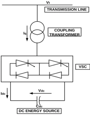
Fig. 1 shows the configuration of STATCOM, which consists of a solid state synchronous voltage source converter (VSC), a coupling transformer and a dc capacitor. The solid state synchronous voltage source converter (VSC) generates a balanced set of three sinusoidal voltages at the fundamental frequency with rapidly controllable amplitude and phase angle.
COUPLING TRANSFORMER
VSC TRANSMISSION LINE
DC ENERGY SOURCE Vdc
Cdc Idc
Iq
Vt
Fig.1 Static Synchronous Compensator (STATCOM)
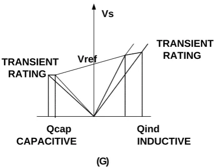
The different modes of STATCOM along with capacitor charging-capacitor discharging, phasor diagrams and V-I & V-Q characteristics are shown in the fig.2. In the capacitive mode, reactive power (Q) is supplied by STATCOM. Similarly in inductive mode, reactive power is absorbed from the system. In case of floating mode reactive power is not supplied as well as absorbed, as there is no demand or gain of the reactive power. Vs is the system voltage whereas Vc is the voltage of STATCOM.
Vc Vs
L
Q
I
(A)
I
Vs
Vc IjɷL
Vc Vs
Q I
(B)
Vs Vc
I
IjɷL
Vc Vs
L
Q=0 I
(C)
Vs
Vc
I
Vc Vs
(D)
Vs
Vc I
(E) IjɷL
α α
Vref Vs
Icap Iind
[image:2.595.86.240.321.518.2]© 2016, IRJET | Impact Factor value: 4.45 | ISO 9001:2008 Certified Journal | Page 403 Vs
Qcap Qind
Vref TRANSIENT
RATING
TRANSIENT RATING
INDUCTIVE CAPACITIVE
[image:3.595.128.560.62.419.2](G)
Fig.2 Operating principle and control characteristics of STATCOM
A. Capacitive mode B. Inductive mode C. Floating mode
D. Capacitor charging mode E. Capacitor discharging mode F. VI characteristics
G. V–Q characteristics
3. POWER SYSTEM STABILIZERS
A Power System Stabilizer is an additional block of a generator excitation controller Automatic Voltage Regulator (AVR). The PSS is added in the electrical power system to improve the overall dynamic performance, especially for the control of electro mechanical oscillations. The Power System Stabilizer consists of auxiliary stabilizing signals such as terminal frequency, shaft speed and/or power to change the input signal to the automatic voltage regulator. PSS is a very effective device of enhancing small-signal stability performance on a power system network. For large power system, PSS does not give satisfied performance under heavy load conditions or faulty conditions, therefore FACTS devices have been introduced into the system where STATCOM gives good performance.
4. MULTI MACHINE POWER SYSTEM MODEL
The system model considered for analysis is a two area multi machine system which is shown in the fig 3. And the system data is shown in the Table 1.GENERATOR1 TRANSFORMER1 BUS 1 BUS 2
Fault
STATCOM
GENERATOR2 TRANSFORMER2
BUS 3
L O A D
Fig. 3 Single line diagram
SYSTEM DEVICE SYSTEM RATING
Generator 1 1000MVA
Generator 2 5000MVA
Transformer 1 1000MVA, 13.8/500KV
Transformer 2 5000MVA, 13.8/500KV
Transmission line 1 350km
Transmission line 2 350km
Three phase load 5000MW
Table1. Data sheet for the system model
The system model consists of 3 phase hydraulic generation plant at the two ends along with the 3 phase transformers which are connected by transmission lines of 500 km. The hydraulic generation plant at the one end is of 1000 MVA capacity whereas the other hydraulic generation plant is of 5000 MVA capacity. The system model consists of two step up transformers which step ups the voltage from 13.8 KV to 500 KV. There are three buses which are connected with the help of transmission lines of 350 km long. At the third bus, three phase load is connected which is of 5000 MW capacity. The performance of the system under the different load conditions along with the different types of faults such as ground fault, three phase fault etc., is observed.
5. SIMULATION RESULTS:-
[image:3.595.43.258.97.264.2]© 2016, IRJET | Impact Factor value: 4.45 | ISO 9001:2008 Certified Journal | Page 404
5.1 CASE I: - When No fault, No STATCOM, No PSS in System
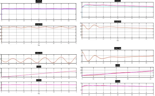
[image:4.595.44.568.217.542.2]The first condition we have taken is when the system is under the normal condition that is there is No fault, No STATCOM and No PSS in the system. Under the normal condition the system behavior is abnormal, that is we get oscillations for the whole time period because the PSS is not present in the system. The bus voltages, line power, rotor angle, rotor speeds and terminal voltages are shown in the figure 4.
0 0.5 1 1.5 2 2.5 3 3.5 4 4.5 5
0 0.5 1 1.5
V pos, seq. B1 B2 B3 (pu)
0 0.5 1 1.5 2 2.5 3 3.5 4 4.5 5
0 200 400 600 800 1000
Time
Line power (MW)
0 0.5 1 1.5 2 2.5 3 3.5 4 4.5 5
50 55 60
d_theta1_2 (deg)
0 0.5 1 1.5 2 2.5 3 3.5 4 4.5 5
1 1.02 1.04
w1 w2 (pu)
0 0.5 1 1.5 2 2.5 3 3.5 4 4.5 5
0 0.5 1 1.5
Time
Vt1 Vt2 (pu)
Fig. 4 Simulation Results when No fault, No STATCOM, No PSS in System
5.2 CASE II: - When NO FAULT, NO STATCOM, With PSS in the system
As under the normal condition the system behavior is unstable. At the instant when PSS is applied into the system, the abnormality in the system is reduced to some extent. Therefore the performance of the system is observed under the two conditions, which are,
Under the light load condition
Under the heavy load condition
5.2.1 Under the light load condition:-
Under the light load condition the behavior of the system is shown in the figure below. The system consists of PSS, but still we get the disturbances because of the reactive power demand by inductive nature of the three phase load. The bus
voltages are shown in the figure which are increased from 1 PU to 1.1 PU, 1.2 PU, 1.3PU, which is not desirable. Similarly the desired power is 1000 MW, but due to the abnormality the line power is reduced to 700 MW.
Similarly, rotor angle, rotor speeds, terminal voltages consists of abnormality even if PSS is present into the system which is shown on the figure 5.
0 0.5 1 1.5 2 2.5 3 3.5 4 4.5 5
0 0.5 1 1.5
V pos, seq. B1 B2 B3 (pu)
0 0.5 1 1.5 2 2.5 3 3.5 4 4.5 5
0 200 400 600 800 1000
Time
Line power (MW)
0 0.5 1 1.5 2 2.5 3 3.5 4 4.5 5
20 40 60
d_theta1_2 (deg)
0 0.2 0.4 0.6 0.8 1 1.2
1 1.02 1.04 1.06
w1 w2 (pu)
0 0.5 1 1.5 2 2.5 3 3.5 4 4.5 5
0 0.5 1 1.5
Time
Vt1 Vt2 (pu)
Fig. 5 Simulation Results Under the light load condition
5.2.2 Under the heavy load condition:-
© 2016, IRJET | Impact Factor value: 4.45 | ISO 9001:2008 Certified Journal | Page 405
0 0.5 1 1.5
0 0.5 1 1.5 2
V pos, seq. B1 B2 B3 (pu)
0 0.5 1 1.5
-2000 -1000 0 1000 2000
Time
Line power (MW)
0 0.5 1 1.5
0 500 1000 1500
d_theta1_2 (deg)
0 0.5 1 1.5
1 1.02 1.04 1.06
w1 w2 (pu)
0 0.5 1 1.5
0 1 2
Time
[image:5.595.43.569.84.394.2]Vt1 Vt2 (pu)
Fig. 6 Simulation Results Under the heavy load condition
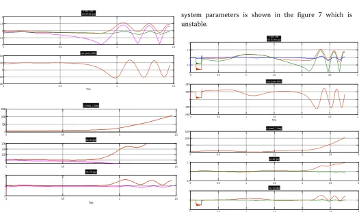
As under the heavy load condition the system becomes unstable even in the presence of PSS. Therefore we can conclude that PSS is not only sufficient to survive the electrical power system for heavy load condition. For more accuracy we need a device which can survive in every possible load conditions as well as under the faulty conditions.
Therefore, FACTS devices have been introduced in the electrical power system which are having abilities to survive the electrical power system under the different load conditions. STATCOM is one of the FACTS device which is used in the electrical power system for reducing the abnormality into the electrical power system which has faster response.
5.3 CASE III:- Under the faulty condition without STATCOM
[image:5.595.309.565.561.710.2]The system is analyzed under the faulty condition, when PSS is present in the system but there is no STATCOM. The fault type is three phase fault which is occurred in the system from 0.1 to 0.18 second. The system behavior is shown in the figure 7. At the time of fault the system will try to survive as PSS is present in the system, therefore it survives for 2.5 seconds but due to 3 phase fault the system will get collapsed which is shown in the figure 7. The nature of the
system parameters is shown in the figure 7 which is unstable.
0 0.5 1 1.5 2 2.5 3
0 0.5 1 1.5 2
V pos, seq. B1 B2 B3 (pu)
0 0.5 1 1.5 2 2.5 3
-2000 -1000 0 1000 2000
Time
Line power (MW)
0 0.5 1 1.5 2 2.5 3
0 500 1000 1500
d_theta1_2 (deg)
0 0.5 1 1.5 2 2.5 3
0.9 1 1.1
w1 w2 (pu)
0 0.5 1 1.5 2 2.5 3
0 1 2
Time
Vt1 Vt2 (pu)
Fig. 7 Simulation Results Under the faulty condition without STATCOM
5.4 CASE IV: - Under the faulty condition with STATCOM
As under the faulty condition the system behavior is fully unstable even in the presence of PSS. Therefore, STATCOM is applied into the system which is well to do in reducing the instability into the system as shown in the figure 8. As shown in the figure the system will become stable when the fault occurs into the system because of the application of STATCOM into the system.
0 0.5 1 1.5 2 2.5 3
0 0.5 1 1.5
V pos, seq. B1 B2 B3 (pu)
0 0.5 1 1.5 2 2.5 3
0 500 1000 1500
Time
© 2016, IRJET | Impact Factor value: 4.45 | ISO 9001:2008 Certified Journal | Page 406
0 0.5 1 1.5 2 2.5 3
0 50 100
d_theta1_2 (deg)
0 0.5 1 1.5 2 2.5 3
0.99 1 1.01 1.02
w1 w2 (pu)
0 0.5 1 1.5 2 2.5 3
0 0.5 1 1.5
[image:6.595.40.292.104.233.2]Time Vt1 Vt2 (pu)
Fig. 8 Simulation Results Under the faulty condition without STATCOM
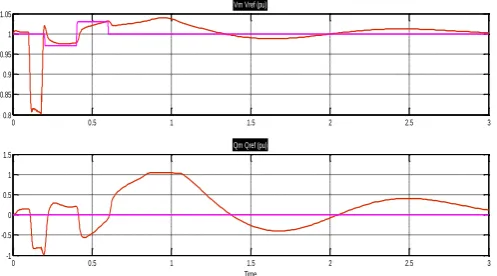
The nature of the STATCOM voltage and the reactive power is shown in the figure 9. When 3 phase fault occurs into the system, the system voltage drops to few extent. The STATCOM provides that amount of voltage to the system which is shown in the figure 9. As shown in the figure STATCOM balances the amount of voltage which is required by the system to become stable.
Similarly the nature of reactive power of the STATCOM is shown in the figure 9. As the fault occurs into the system the reactive power suddenly drops that is reactive power required by the load is more. STATCOM provides this amount of reactive power to the load and balances the amount of reactive power required by the load to become stable which is shown in the figure 9.
0 0.5 1 1.5 2 2.5 3
0.8 0.85 0.9 0.95 1 1.05
Vm Vref (pu)
0 0.5 1 1.5 2 2.5 3
-1 -0.5 0 0.5 1 1.5
Time
Qm Qref (pu)
Fig. 9 Simulation Results showing the nature of the STATCOM voltage and the reactive power
6. .CONCLUSION
This Paper deals with the applications of Static Synchronous Compensator for the performance improvement of the Electrical Power System. The detailed model of STATCOM was implemented and tested in MATLAB/Simulink environment. The verification of the STATCOM under the
steady state condition is tested in the MATLAB/Simulink environment. The system behavior is observed under the various conditions with STATCOM and without STATCOM. The behavior of the system parameters are then observed. The system parameters are the bus voltages in per unit, line power in MW, rotor angle in degree, rotor speeds in per unit and terminal voltages in per unit. The system model is applicable for voltage stability analysis. The effects of STATCOM installed in power transmission path are analyzed in this paper and the conclusion as follows:
Even in the presence of PSS the system behavior under the heavy load condition as well as in faulty condition is fully unstable. The STATCOM improves the performance of the electrical power system under the heavy load condition as well as in the faulty conditions.
The STATCOM gives superior performance for the power measurement, bus voltages and rotor angle and terminal voltages of the multi-machine system. The best performance has been obtained by introducing FACTS devices that is STATCOM which compensate reactive power, it’s concluded that by introducing FACTS device system behavior, voltage stability and transmission capability improves considerably.
REFERENCES
[1] Prity Bisen and Amit Shrivastava,
“Comparison between SVC and STATCOM FACTS Devices for Power System Stability Enhancement”,
International Journal on Emerging Technologies , pp 101-109
[2] K. R. Padiyar, “FACTS CONTROLLERS IN
POWER TRANSMISSION AND DISTRIBUTION” ,
NEW AGE INTERNATIONAL PUBLISHERS, pp 173-177
[3] Prabha Kundur,“Power System Stability
And Control”, TATA McGRAW-HILL EDITION, pp 335
[4] Arindam Chakraborty,1Shravana K.
Musunuri,Anurag K. Srivastava, and Anil K. Kondabathini, “Integrating STATCOM and Battery Energy Storage System for Power System Transient Stability: A Review and Application”, Hindawi Publishing Corporation Advances in Power Electronics
[5] B. Singh, R. Saha, A. Chandra, K. Al-Haddad, ”Static
[image:6.595.40.289.493.631.2]