AIRCRAFT FLIGHT DYNAMICS ANALYSIS
OUTMAN MOHAMED ALAZOMUI
ABSTRACT
CONTENTS
TITLE i
DECLARATION ii
ACKNOWLEDGEMENT iii
ABSTRACT iv
CONTENTS vi
LIST OF TABLES ix
LIST OF FIGURES x
CHAPTER 1 INTRODUCTION 1
1.1 Introduction 1
1.2 Back ground 2
1.3 Problem statements 3
1.4 Thesis objective 4
1.5 Scope of study 4
CHAPTER 2 LITERATUER REVIEW 6
2.1 Overview Flight Equation of Motion 6
2.2 Flight Controls System 7
2.3 Aircraft Control Surfaces 8
2.4 Aerodynamic forces and drag polar 10 2.5 Controlling the motion of flight 11
2.5.1 Elevator 12
2.5.2 Ailerons 15
2.5.3 Rudder | yaw 17
2.6 Center of gravity 21 2.7 Coordinate systems and equations of' motion 22
2.7.1 particle motion 22
2.7.2 Coordinate System (Flat Nonrotating Earth) 22 2.7.3 Description of coordinate system 23
2.8 Flight dynamics. 24
2.8.1 Stability and control analyses 24 2.8.2 Basic concepts about airplane stability and control 25 2.8.3 Possible types of motions following a disturbance. 26 2.8.4 Static stability and dynamic stability 27 2.8.5 The definitions of static and dynamics stability 28
2.8.5.1 Static Stability: 28
2.8.5.2 Dynamic Stability: 28
2.9 Lateral stability behavior 31
CHAPTER 3 METHODOLOGY 33
3.1 The Equations of Motion of an Aircraft 33
3.1.1 Introduction 33
3.2 Governing Equation of Flight Motions 34 3.4 Simplified form of the Governing Equation
of flight Motion 39
3.4.1 Longitudinal Equations 40
3.4.2 Lateral-Directional Equations 41 2.8.1 lateral-Directional transfer function 45
CHPTER 4 DISCUSSIONS AND RESULTS 51
4.1 Introduction 51
4.1.1 Summarized the lateral – directional flight motion 51 4.2 The required data for lateral-directional
flight motion analysis 52
4.3 Lateral stability analysis Behaviour of propeller
driven aircraft Cessna-182 aircraft 53 4.3.1 Technical Data of Cessna 182 53 4.3.2. The aerodynamic data for lateral stability
4.3.3. Result of Cessna -182 lateral stability analysis 56 4.4. Lateral Stability Analysis Behaviour of Propeller
Driven Aircraft Beech 99 aircraft 59
4.4.1 Technical Data of Beech 99 59
4.4.2. The aerodynamic data for lateral stability
analysis Beech 99 60
4.4.3 Result of Lateral Stability Analysis Beech 99 62 4.5 Lateral Stability Analysis Behaviour of Aircraft
Learjet 24 aircraft 64
4.5.1 Technical Data of Learjet 24 65 4.5.2 The aerodynamic data for lateral stability
analysis Learjet 24 66
4.5.3 Result of Lateral Stability Analysis Learjet 24 68 4.6 Lateral Stability Analysis Behaviour of jet
engine driven Aircraft Lockheed F-104 aircraft 70 4.6.1 Technical Data of Lockheed F-104 71 4.6.2 The aerodynamic data for lateral stability
analysis Lockheed F-104 71
4.6.3 Result of Lateral Stability Analysis Lockheed F-104 73
CHAPTER 5 CONCLUSION AND THE FUTURE WORK 96
5.1 CONCLUSION 96
5.2 THE FUTURE WORK 97
REFERENCES 98
LIST OF TABLES
2.1 The function of controls surfaces 7 2.2 Elevator size of different aircraft 11
2.2 (continued) 12
2.3 Aileron size for different aircrafs 14 2.4 The rudder size for several aircrafts 17
2.5 Static and dynamic stability 25
2.6 lateral –directional roots of the general aviation airplane 40
4.1 The Cessna -182 geometry data 48
4.2 The Cessna -182 flight condition data 48 4.3 The mass and inertial data of Cessna 182 48 4.4 The lateral-Directional Stability Derivative of Cessna 182 49 4.5 The lateral-Directional control derivatives of Cessna 182 49
4.6 The Beech 99 geometry data 53
4.7 The Beech 99 flight condition data 54 4.8 The mass and inertial data of Beech 99 54 4.9 The lateral-Directional Stability Derivative of Beech 99 54 4.10 The Lateral-Directional Control Derivatives of Beech 99 55
4.11 The Learjet 24 geometry data 59
LIST OF FIGURES
1.1 Stability the longitudinal flight mode and lateral
flight mode 3
2.1 primary control surfaces on typical light aircraft 7 2.2 aerodynamic forces acting on an aircraft 8
2.3 four forces of flight 9
2.4 aircraft control surfaces 9
2.5 elevator and pitch moveent 10
2.6 Top-view of the horizontal tail and elevator. 11
2.7 ailerons and roll movement 13
2.9 rudder and yaw movement the 15
2.10 Directional control via rudder deflection (top view) 16 2.11 Vertical tail and rudder geometry 16
2.12 center of gravity 18
2.13 General rectangular-coordinate system 20 2.14 Types of motion following a disturbance 22
2.15 Cessna 182 aircraft. 28
3.1 free response (lateral-directional) of the general
aviation airplane 40
3.2 Unit-step response (lateral-directional) of the
general aviation airplane: Roll angle 44 4.1 Shows a three dimensional view drawing of Cessna 182. 47 4.2 Aileron deflection under a single doublet impulse mode 50
4.3 A side slip angle β response 51
4.4 A roll angle Φ response 51
4.5 A yaw angle Ψ response 52
4.6 Shows a three dimensional view drawing of Beech 99. 53 4.7 Aileron deflection under a single doublet impulse mode 55
4.8 A side slip angle β response 56
4.9 A roll angle Φ response 56
4.11 Shows a three dimensional view drawing of Learjet 24 58 4.12. Aileron deflection under a single doublet impulse mode 61
4.13 A side slip angle β response 61
4.14 A roll angle Φ response 62
4.15 A yaw angle Ψ response 62
4.16 Shows a three dimensional view drawing of
Lockheed F-104. 64
4.17 Aileron, and rudder deflection under a single doublet
impulse mode 75
4.18 A sideslip angle β response 75
4.19 A roll angle Φ response 76
4.20 A yaw angle Ψ response 77
4.21 A sideslip angle β response 77
4.22 A roll angle Φ response 78
4.23 A yaw angle Ψ response 79
4.24 Aileron, and rudder deflection under multiple doublet impulses mode 81
4.25 A sideslip angle β response 81
4.26 A roll angle Φ response 82
4.27 A yaw angle Ψ response 83
4.28 A sideslip angle β response 83
4.29 A roll angle Φ response 84
4.30 A yaw angle Ψ response 85
4.31 Aileron, and rudder deflection under a single doublet mode 85
4.32 A sideslip angle β response 86
4.33 A roll angle Φ response 87
4.34 A yaw angle Ψ response 88
4.35 A sideslip angle β response 88
4.36 A roll angle Φ response 89
4.37 A yaw angle Ψ response 90
4.38 A sideslip angle β response 90
4.39 A roll angle Φ response 91
4.41 A roll angle Φ response 93
4.42 Yaw angle Φ response 94
4.43 A yaw angle Ψ response 94
4.44 A roll angle Ψ response 95
CHAPTER 1
INTRODUCTION
1.1 Introduction
The aircraft flight behavior can be split into two flight modes: longitudinal flight mode and lateral flight mode [1] [2] [3]. The longitudinal flight mode concern with the flight behavior in the vertical plane, namely with the aircraft movement in the horizontal and vertical direction with flight direction change due to the aircraft rotation with respect to the lateral axis. The lateral flight mode related to the aircraft behavior in the lateral plane. The heading, banking and sliding are part of flight behavior in the lateral flight mode [1].
behavior of two class of aircraft model: propeller driven airplane and jet engine aircraft [1][2].
1.2 Back ground
There is a broad area of research behind using programming languages to calculate many different concepts and variables of flight dynamics in aircrafts. The programming language MATLAB is used in many cases, and has helped contribute to this vast field of research [1][2].
There is an incremental rate of success and many new observations have come to play after using matlab to find these different estimates within flight dynamics [2]. At the beginning of the study of any subject, it is helpful to know its definition, scope and special features. It is also useful to know the benefits of the study of the subject, background expected, approach, which also indicates the limitations, and the way the subject is being developed. In this chapter these aspects are dealt with [2].
Flight dynamics deals principally with the response of aerospace vehicles to perturbations in their flight environments and to control inputs. In order to understand this response, it is necessary to characterize the aerodynamic and propulsive forces and moments acting on the vehicle, and the dependence of these forces and moments on the flight variables, including airspeed and vehicle orientation. [3].
Type equation here.
Figure 1.1 Stability the longitudinal flight mode and lateral flight mode [3]
1.3 Problem statements
The aircraft motion basically can be split in two form of motions: the longitudinal motion and the lateral- directional motion. In the second type of motion, the aircraft is controlled by the movement of the aileron, rudder and engine thrust. These three elements represent the driving force how the aircraft flies in the lateral-directional direction. The present work will carry out investigation the flight behavior in that two directions due to the operations of aileron and rudder independently or simultaneously combine with the change of engine thrust.
1.4 Thesis objective
The objectives of the research work are develop computer code written in MATLAB programming language in order to allow one to evaluate the dynamics stability behavior in the lateral- directional direction. This developed computer code will be used to evaluate the lateral and directional behavior over four type aircraft models. The first two aircraft model belongs to the class of a propeller driven aircraft as (Beech 99 aircraft, Cessna 182 aircraft) and while the other two aircraft model are jet engine aircraft as (Learjet 24 aircraft, Lockheed F-104 aircraft). Here the aileron and rudder movement are modeled by introducing their movement in the form a single or multiple doublet impulses.
In combining with thrust, such aileron and rudder movement will determine the aircraft behavior in term of horizontal flight speed u, aircraft‟s yaw angle Ψ, bank angle ф, the rotational velocity in roll and yaw and aircraft position in respect to the prescribed inertial coordinate system.
1.5 Scope of study
(i) Understanding coordinate system applied to the airplane namely the earth coordinate system, aircraft body axis coordinate system and the aircraft stability coordinate system;
(ii) Derivation the governing equation of flight motion in general and in specific flight motion;
(iii) The implementation of the developed computer code for analyzing four types aircraft model;
CHAPTER 2
LITERATUER REVIEW
2.1 Overview Flight Equation of Motion
to run various operating conditions. This will enable the study of the response and stability characteristics various aircraft parameters.
However to arrive on truly in developing flight simulator, one to follow certain steps, one have to be able to evaluate the aircraft behavior in linear as well as in nonlinear of the aircraft flight of motion. The linear form of the equation‟s aircraft flight of motion is derived from the nonlinear equation of flight motion by introducing small perturbation from flight equilibrium condition. The equation of flight motion in linear form can be defined to describe the flight motion in longitudinal direction or in the lateral – directional motion. It is necessary to be noted that aircraft in flight is free to rotate in three dimensions: pitch, nose up or down about an axis running from wing to wing, yaw, nose left or right about an axis running up and down; and roll, rotation about an axis running from nose to tail. These three axes are called as lateral, vertical, and longitudinal axis. These axes move with the vehicle, and rotate relative to the Earth along with the craft. The longitudinal motion is the motion of aircraft with respect to the vertical plane only and the rotation just occur only with respect to the lateral axis. While lateral motion is considered as the movement of the aircraft in horizontal plane with aircraft allow to rotate with respect the vertical or longitudinal axis. In this two types of motion, longitudinal and lateral motion, in respect to the rotation motion can be managed by aircraft control surfaces. These aircraft control surfaces combined with other devices generate a system a flight Control System.
2.2 Flight Controls System
2.3 Aircraft Control Surfaces
To control the airplane‟s trajectory, it can be done by changing the external surfaces of the aircraft. Such external surfaces are elevators, stabilators, canards, elevons, tailerons, ailerons, rudders, and thrust vectoring nozzles. These external surfaces are often called as primary surfaces. Any operation applied to the primary surface will produce aircraft movement in pitch, roll, and yaw motion. Secondary flight control surfaces augment the primary surfaces by modifying the lift and drag characteristics of the wings and airplane. These secondary surfaces include wing flaps (usually on the trailing edge but sometimes used on the leading edge), wing slats, spoilers, and speed brakes. The recent terminology for primary flight controls is “flight control effectors,” as the effector may not be a conventional control surface. For example, NASA‟s F-15 ACTIVE research aircraft is said to have nine flight control effectors: left and right canards, left and right ailerons, rudder (the two rudders move together and are treated as one effector), left and right stabililators, and pitch or yaw TV (thrust vectoring) [2].
Figure 2.1: primary control surfaces on typical light aircraft [5]
Table 2.1 The function of controls surfaces[6].
Control surface Movement Axis
Pitch Elevator Nose up /down Lateral
Roll Aileron Wings up /down Longitudinal
Yaw Rudder Nose left/right Vertical
2.4 Aerodynamic forces and drag polar
[image:19.595.122.504.298.456.2]The resultant or vector aerodynamic force is produced by the motion of the aircraft through the atmosphere. the resultant aerodynamic force is resolved into two components along the wind-axes as shown in figure 2.2. the component in the opposite direction to the aircraft‟s velocity vector is called the drag and given the symbol D . the drag resists the motion of the aircraft. the component perpendicular to the aircraft velocity is called lift and given the symbol L . it is the lift that keeps the aircraft in the air [6][7].
Figure 2.2 aerodynamic forces acting on an aircraft[6]
Figure. 2.3 four forces of flight [6]
A force can be thought of as a push or pull in a specific direction. it is a vector quantity, which means a force has both a magnitude (amount) and a direction for this lesson we will deal specifically with fixed-wing airplanes. other aircraft, such as hot air balloons and helicopters, use the same basic principles but the physics are very different [10][11].
2.5 Controlling the motion of flight
Figure. 2.4 aircraft control surfaces[6]
2.5.1. Elevator
Pitch as the name implies, the elevator helps “elevate” the aircraft. it is usually located on the tail of the aircraft and serves two purposes. the first is to provide stability by producing a downward force on the tail. airplanes are traditionally nose-heavy and this downward force is required to compensate for that. the second is to direct the nose of the aircraft either upwards or downwards, known as pitch, in order to make the airplane climb and descend figuer 2.5[14].
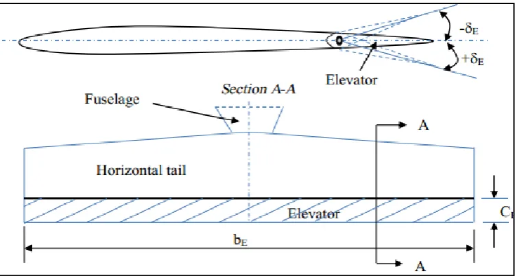
[image:21.595.121.519.515.719.2]Elevator is a primary control surface placed on the trailing edge of the horizontal tail or canard. longitudinal control and long itudinal trim are two main functions of the elevator; and it has minor influence on the longitudinal stability. elevator is flap-like and is deflected up and down. with this deflection, the camber of the air foil of the tail is changed, and consequently tail lift coefficient (clh) is changed. the main objective of elevator deflection is to increase or decrease tail plane lift and hence tail plane pitching moment [6].
Figure 2.6 Top-view of the horizontal tail and elevator.
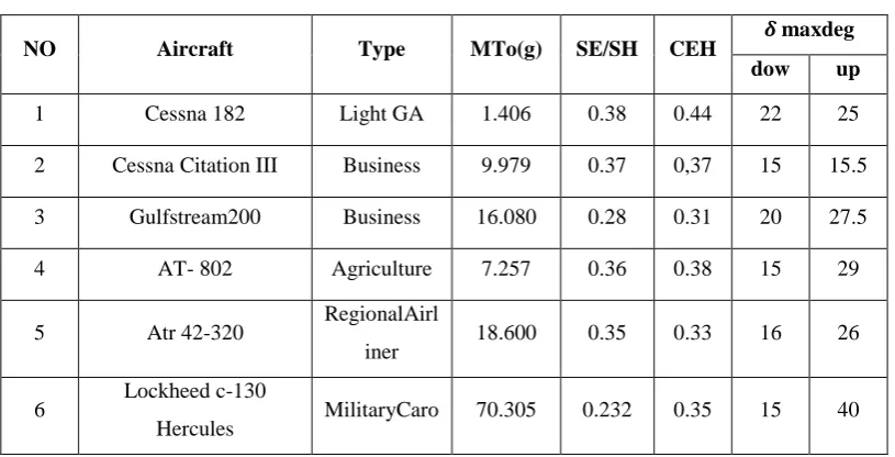
Table 2.2 Elevator size of different aircraft[6][12]
NO Aircraft Type MTo(g) SE/SH CEH maxdeg dow up
1 Cessna 182 Light GA 1.406 0.38 0.44 22 25
2 Cessna Citation III Business 9.979 0.37 0,37 15 15.5
3 Gulfstream200 Business 16.080 0.28 0.31 20 27.5
4 AT- 802 Agriculture 7.257 0.36 0.38 15 29
5 Atr 42-320 RegionalAirl
iner 18.600 0.35 0.33 16 26
6 Lockheed c-130
Hercules MilitaryCaro 70.305 0.232 0.35 15 40
Table 2.2 (continued)
7 Fokker F-28-4000 Transport 33.000 0.197 0.22 15 25
8 Fokker F-100B Airliner 44.450 0.223 0.32 22 25
9 McDonnell Douglas
DC- 8 Transport 140.600 0.225 0.25 10 25
10 McDonnell Douglas DC
9-40 Transport 51.700 0.28 0.30 15 25
11 McDonnell Douglas DC
10-40 Transport 251.700 0.225 0.25 16.5 27
12 McDonnell
DouglasMD-11 Transport 273.300 0.31 0.35 20 37.5
13 Boeing 727-100 Transport 76.820 0.23 0.25 16 26
14 Boeing 727-100 Transport 50.300 0.224 0.25 20 20
15 Boeing 727-200 Transport 247.20 0.30 0.32 25 30
16 Boeing 727-200 Transport 377.842 0.185 0.23 17 22
17 Airbus A-300B Transport 165.000 0.295 0.30 - -
18 Airbus 320 Transport 78.000 0.31 0.32 17 30
19 Airbus A340-600 Airliner 368,000 15 30
20 lOckheed L-1011 Tristar Transport 231.000 0.215 0.23 0 25
[image:23.595.115.519.332.734.2]2.5.2 Ailerons
[image:24.595.135.503.366.575.2]The aileron is introduced as part of the aircraft configuration is to make the aircraft can roll. This devices are located at the rear of the wing, one on each side. They work opposite to each other, so when one is raised, the other is lowered. Their job is to increase the lift on one wing, while reducing the lift on the other. By doing this, they roll the aircraft sideways, which allows the aircraft to turn. This is the primary method of steering a fixed-wing aircraft figuer(2.7)[7].
Figure 2.7 ailerons and roll movement[6]
and simultaneously to produce a rolling moment about x-axis. therefore, the main role of aileron is the roll control; however it will affect yaw control as well. Roll control is the fundamental basis for the design of aileron[14] .Figure show the wing top view drawing which indicate the location of the aileron on the wing. While Figure … shows the aileron deflection angle which allow it can be done up and down deflection. Table … shows typical dimension of aileron size for various type of aircraft.
[image:25.595.106.503.444.591.2]Figure … A-Top-view of the wing and aileron[14]
Table 2.3. aileron size for different aircrafs[14]
NO Aircraft Type (kg)
B
(m) /
C
Span ratio (deg)
/b/2 /b/2 up Dow
1 Cessna 182 Light GA 1.406 11 0.2 0.46 0.95 20 14
2 CessnaCitatio
n III Business jet 9.979 16.31 0.3 0.56 0.89 12 12.5
3 AirTractorAT
802 Agriculture 7.252 18 0.36 0.4 0.95 17 13
4 Gulfstream
200 Business jet 16.080 17.7 0.22 0.6 0.,86 15 15
5 Fokker 100A Airliner 44.450 28.08 0.24 0.6 0.94 25 20
6 Boeing
777-200 Airliner 247.200 60.9 0.22 0.32 0.76
28
30 10
7 Airbus
340-600 Airliner 368.000 63.45 0.3 0.64 0.92 25 20
8 Airbus
A340-600 Airliner 368.000 63.45 0.25 0.67 0.92 25 25
2.5.3 Rudder | yaw
are often slower at turning an aircraft than the ailerons, but they can turn the aircraft without rolling it and are useful for small adjustments during takeoff, landing and other flights. Sometimes a pilot uses both the rudder and the ailerons together while turning in order to produce a smoother flight. As shown in the Figure 2.9 [14].
Figure. 2.9 rudder and yaw movement the[14]
Figure 2.10 Directional control via rudder deflection (top view)[13]
there are interferences between rudder and aileron, and they are often applied simultaneously. Thus, the lateral and directional dynamics are frequently coupled. thus, it is a good practice to design aileron and rudder concurrently. Rudder, similar to elevator, is a displacement control device, while the aileron is a rate control device. The fundamentals of design of elevator and rudder are similar, but since their applications are different, the design of rudder is generally more complicated. However rudder deflections to the right and to the left are the same, but up and down elevator deflections are different
[image:28.595.130.517.450.659.2]In the design of the rudder, four parameters must be determined. they are: (i) Rudder area (sr); (ii) Rudder chord (cr);
(iii) Rudder span (br);
(iv) Maximum rudder deflection ( rmax); and
[image:29.595.130.513.245.721.2](iv) Location of inboard edge of the rudder (bri);
Table 2.4 show the typical size rudder for differents type of aircraft[14].
NO Aircraft Type (kg) (deg)
1 Cesna 182 Light GA 1.406 0.38 0.42
2 Cesna 650 Business jet 9.979 0.26 0.27
3 Gulfstream 200 Business jet 16.080 0.3 0.32
4 Air tractor AT-802
Regional
airlines 18.600 0.61 0.62
5 LockheedC-130E
Hercules Minitary cargo 70.305 0.239 0.25 35
6 DC-8 Transport 140.600 0.269 35
7 DC-10 Transport 251.700 0.145 38
8 Boeing 737-100 Transport 50.300 0.25 0.26
9 Boeing 777-200 Transport 247.200 0.26 0.28
10 Boeing 747-200 Transport 377.842 0.173 0.22
11 Lockheed C-5A Cargo 381.000 0.191 0.2 -
12 Fokker 100A Airliner 44.450 0.23 0.28
13 Embraer ERJ 145 Regional jet 22.000 0.29 0.31 15
2.5.4 Rudder design requirements
The design requirements of rudder are primarily driven by directional control and directional trim. directional control is governed mainly through yaw rate (r); While directional trim is often governed by maximum rudder deflection. Faa has a number of regulations for directional control; All of which must be addressed by a rudder designer.
2.6 Center of gravity
[image:30.595.121.527.495.687.2]The center of gravity, also known as cg, is the effective point whereby all weight is considered to be. The cg is also the same point where the axes of flight meet figure 2. 11 This point isn‟t fixed on any aircraft, but moves forwards or backwards along the longitudinal axis, depending on how the aircraft is loaded. It is vital that its center of gravity remain within certain limits however, as an aircraft that is too nose- or tail-heavy will either not fly, or be so difficult to control that it becomes too dangerous to try. These limits are referred to as its operational envelope[4].
2.7 Coordinate systems and equations of' motion:
In order to describe the motion of a dynamic system it is n ary to define a suitable coordinate system and formulate equations for the motion in accordance with the physical laws governing the system. The diagrams and discussion that follow consider the motion of a particle (point mass) and the more complicated motion of a rigid body.
2.7.1 particle motion
Coordinate systems and equations that conveniently describe the motion of a point mass are presented in the following pages. rectangular, spherical, and cylindrical coordinate systems are presented. Preferred axis orientation and notation indicated and used are consistent, insofar as possible, with the reference literature.
2.7.2 COORDINATE SYSTEM (FLAT NONROTATING EARTH )
2.7.3 Description of coordinate system
In defining the coordinate system applied in the Flight Dynamic study is normally use a rule as follows:
(i) Origin of rectangular coordinates x, y, z: arbitrary, often a point on the surface of the earth;
(ii) Fundamental plane: usually the xy-plane; tangent to the surface of the earth at the origin;
(iii) Positive x•axis: arbitrary, often selected along initial heading or direction of motion.
(iv) Positive z-axis: arbitrary, often oriented in sense to denote altitude above the surface of earth or the xy-plane;
[image:32.595.116.513.415.603.2](v) Positive rotation in fundamental plane: from x-axis to y-axis; i.e., right-hand system as depicted in the Figure 2.13;
2.8 Flight dynamics.
Flight dynamics deals principally with the response of aerospace vehicles to perturbations in their flight environments and to control inputs. In order to understand this response, it is necessary to characterize the aerodynamic and propulsive forces and moments acting [17][18].
Flight dynamics: It‟s a branch of dynamics dealing with the motion of an object moving in the earth‟s atmosphere. The study of flight dynamics will enable us to (a) obtain the performance of the airplane which is described by items like maximum speed, minimum speed, maximum rate of climb, distance covered with a given amount of fuel, radius of turn, take-off distance, landing distance etc., (b) estimate the loads on the airplane, (c) estimate the power required or thrust required for desired performance, (d) determine the stability of the airplane i.e. whether the airplane returns to steady flight conditions after being disturbed and (e) examine the control of the airplane. Flight dynamics is a basic subject for an aerospace engineer and its knowledge is essential for proper design of an airplane [18].
2.8.1 Stability and control analyses
REFERENCES
1. Air craft dynamics from modeling to simulation, Professor Marcello R. Napolitano - 2012
2. Airplane flight dynamics and automatic flight controls - Jan Roskam – part I - 2009
3. Anderson, Jr. J.D. “Introduction to flight” McGraw Hill 2005.
4. Bandu N. pamadi Performance stability, Dynamics,and control of Airplanes second edition (2008)
5. CF-104 Starfighter, 1961-1986, CFB Baden-Soellingen, 1986. 6. Chetayev, N.G. “The stability of motion”, Pergamon 1961.
7. Clearwater, John, Canadian Nuclear Weapons, Dundurn Press, Toronto, 1998.
8. Dianwei, Q., Jianqiang, Y., Dongbin, Z. & Hua, X. Dynamic Analysis and Model Transformations of Longitudinal Flight of Hypersonic Aircrafts, at. Paper read at Innovative Computing Information and Control, 2008. ICICIC '08. 3rd International Conference on: 487-487. 18-20 June 2008.
9. Dommasch, D.O. Sherby, S.S. and Connolly, T.F. “Airplane aerodynamics” Pitman (1967).
10. Engineering Flight Simulator Using MATLAB, Python and FLIGHTGEAR Istas F. Nusyirwan Department of Aeronautical Engineering, Faculty of Mechanical Engineering Universiti Teknologi Malaysia [email protected].
11. Fairhall, David (25 January 2000). "John W R Taylo.
13. Hall, W. Earl, and Narendra K. Gupta. "System identification for nonlinear aerodynamic flight regimes." Journal of Spacecraft and Rockets 14.2 (1977): 73-80.
14. Hansen, James R. The Bird is on the Wing: Aerodynamics and the Progress of the American Airplane. No. 34. Texas A & M University Press, 2004.
15. http://www.free-online-private-pilot-ground school.com/aircraft-ucture.html
16. http://www.wingsoverkansas.com/history/a199/
17. Jameson, Antony. "Aerodynamic design via control theory." Journal of scientific computing 3.3 (1988): 233-260.
18. Jaroszewicz, Adam, et al. "Biomimic sensors guided flight stability and control for flapping wings autonomous micro air vehicle (entomopter)." AIAA Paper 664 (2007)
19. Jump up to:ab Grady, Mary (22 July 2012). "Cessna Unveils Jet An Engine For Skylane". AVweb. Retrieved 24 July 2012.
20. Marcello Napolitano (Aircraft Dynamics: From Modeling to Simulation) October 2011, ©2012
21. Miele, A. “Flight mechanics Vol. I” Addison Wesley (1962).
22. Nasa “Principle of Flight, http://www.answers.com/topic/flight-controls
23. NAxes / Control Surfaces ASA.
http://flight.nasa.gov/pdf/axes_control_surfaces_5-8.pdf
24. Pickler, R., and Milberry, L., Canadair - The First 50 Years, CANAV Books, Toronto, 1995.
25. R. K. Heffley & W. F. Jewell, Aircraft Handling Qualities Data, NASA CR-2144, December 1972
26. Reynerson, Charles. "Aerodynamic Disturbance Force and Torque Estimation for Spacecraft and Simple Shapes Using Finite Plate Elements– Part I: Drag Coefficient." 29th Annual AAS Guidance and Control Conference. 2007.
27. Sadraey, Mohammad. "Design of Control Surfaces." Aircraft Design: A Systems Engineering Approach: 631-753.(2012)
29. See “MU-2B Series Airplane Safety Evaluation Report,” FAA, December 2005; page 20.
30. Shames, I.H. and Krishna Mohana Rao, G. “Engineering mechanics – statics and dynamics”, 4th Edition, Dorling Kindersley (India), licensees of Pearson Education (2006).O LONG BEACH CA, 1965.
31. The lander, J. A. Aircraft Motion Analysis. DOUGLAS AIRCRAFT CMiele, A. “Flight mechanics Vol I” Addison Wesley (1962).
![Figure 1.1 Stability the longitudinal flight mode and lateral flight mode [3]](https://thumb-us.123doks.com/thumbv2/123dok_us/8769140.898014/12.595.137.498.69.276/figure-stability-longitudinal-flight-mode-lateral-flight-mode.webp)
![Table 2.1 The function of controls surfaces[6].](https://thumb-us.123doks.com/thumbv2/123dok_us/8769140.898014/18.595.119.518.221.562/table-function-controls-surfaces.webp)
![Figure 2.2 aerodynamic forces acting on an aircraft[6]](https://thumb-us.123doks.com/thumbv2/123dok_us/8769140.898014/19.595.122.504.298.456/figure-aerodynamic-forces-acting-aircraft.webp)
![Figure. 2.3 four forces of flight [6]](https://thumb-us.123doks.com/thumbv2/123dok_us/8769140.898014/20.595.128.513.77.282/figure-forces-flight.webp)
![Figure 2.5 elevator and pitch moveent[6]](https://thumb-us.123doks.com/thumbv2/123dok_us/8769140.898014/21.595.130.484.79.231/figure-elevator-and-pitch-moveent.webp)
![Figure 2.7 ailerons and roll movement[6]](https://thumb-us.123doks.com/thumbv2/123dok_us/8769140.898014/24.595.135.503.366.575/figure-ailerons-and-roll-movement.webp)
![Figure … A-Top-view of the wing and aileron[14]](https://thumb-us.123doks.com/thumbv2/123dok_us/8769140.898014/25.595.134.505.223.373/figure-view-wing-aileron.webp)
![Table 2.3. aileron size for different aircrafs[14]](https://thumb-us.123doks.com/thumbv2/123dok_us/8769140.898014/26.595.109.531.111.444/table-aileron-size-different-aircrafs.webp)
