© 2017, IRJET | Impact Factor value: 5.181 | ISO 9001:2008 Certified Journal | Page 653
Automated Storage & Retrieval System
Girish Dalvi1 Sanjay Rukhande1
1 Assistant Professor, Department of Mechanical Engineering, FCRIT, Vashi, Navi Mumbai
E-mail: [email protected], [email protected]
---***---Abstract— Inindustrial design ,Effective space utilization is of prime importance. The need of an efficient and compact material handling system( MHS) in vertical direction is arising day by day. This MHS may be used to transfer the material at higher rate than some existing material handling system.
In this paper, The concept which eliminates the process of manually carrying the items, the need of the workers carrying the items and to maximize vertical space utilization is suggested. The design of an electronically operated vertical storage system is carried out and tested successfully. The design principle is based on the adaptation of vertical carousel system. The ‘Automated Shelves’ is a motor-driven vertical storage equipment that brings shelves up and down so that they can be easily available for the user. Design drawings are prepared and based on functionality, durability, cost and local availability, the components/materials selections is done. The system performance was tested on fabricated model. It has wide applications in material handling for industrial, domestic and commercial purpose.
Keywords— vertical carousel system ; automated Shelves; material handling equipment
I. INTRODUCTION
Automated shelves is a material handling equipment. Various manufacturing processes are carried out on multiple floors. For example while manufacturing wafers, soaps, biscuits and other cookies and also on various assembly lines different processes are carried out at multiple stations. These stations are built on multiple floors for optimizing the space utilization. Also the finished goods are stored at a higher level on racks. Thus Organizations are trying to utilize every inch of space. In wholesale stores, there is limited storage space available. Business owners try to capitalize on their existing space to accommodate maximum goods. Due to this, they incure losses due to damage of goods. Also, they have to employ people specifically to handle the goods which are stored at the places which are not easily accessible. This paper presented the design of an efficient system which will transfer the material between lower to higher level. A system is designed in such a way so as to maximize the utilization of vertical air space and
[image:1.595.360.529.306.477.2]reduce the floor space consumption. The purpose of this work was to design and fabricate an automated vertical material handling system in order to ease the process of storing and handling the products stored at inaccessible heights. The system is designed for the storage of shoes in the stores. The capabilities of the proposed system are not limited to the storage of shoes but also designed to carry books or similar sized products when applied for commercial or domestic use.
Fig.1.Vertical Carousel Storage System used in industry
[1]
Figure 1 shows the Vertical Carousel Storage System used in industry. The major parts of the system are the main frame, electronic brake AC motor, the chain drive for motor power transmission, the transmission shaft, main chain drives for the shelves, chain to shelf attachment, shelves and control system. These parts are fabricated / selected and then assembled following the design specifications.
II.
METHODOLOGY
© 2017, IRJET | Impact Factor value: 5.181 | ISO 9001:2008 Certified Journal | Page 654
The automated shelves consists of following components:
1) Main Frame
2) Electromagnetic Brake AC Motor
3) Chain drive for motor power transmission 4) Transmission Shaft
5) Main Chain drive for Shelves 6) Shelf to Chain Attachment 7) Shelves
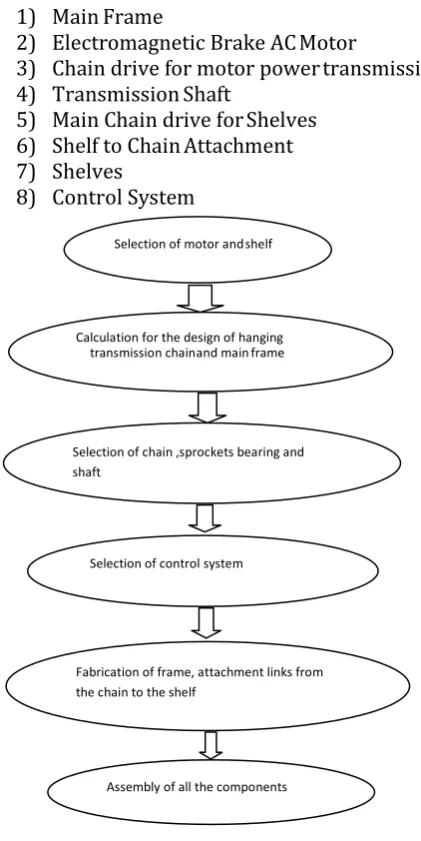
[image:2.595.46.257.126.547.2]8) Control System
Fig.2 Methodology for Automated shelves
III.
Functional aspects
Functional aspects of various components used in the assembly is illustrated as below.
a.
Electromagnetic brake AC Motor
The main function of the motor is to drive and stop the whole vertical conveyer system according to the user requirement. If the motor requires to be stopped instantaneously, electromagnetic brake ac motor is used. Since the electromagnetic brakes exert holding power even while the power is off, they are ideal for use as emergency brakes and in vertical load applications. The electromagnetic brake motor is employed if the load should be maintained.
Specifications of motor selected:
Motor type: Electromagnetic Brake AC motor Rated power: 0.1 hp and Output RPM: 25 rpm
b.
Metallic Frame
The metallic frame supports all the elements of the system. The sprockets of the chain drive are to be mounted on the frame. Material Used for the shelf is MS Hollow Square Tubing. Dimension of material is 50 x 50 mm.
Frame Dimensions after the design calculations are as follows:
i.Length = 900 mm
ii.Width = 960 mm
iii.Height = 1750 mm
c.
Shelves
The shelves will be carrying the load i.e. all the products will be stored in them. Material selected for shelf is plastic so as to make the shelf lighter. The base of the shelves is 600 x300 mm2. The height of the shelf is 200mm. The self-weight of the shelf is 0.6 kg. Eight such shelves are used. The maximum load that each shelf carries is 4 kg.
d.
Chain Drive
Procedure for the design of hanging transmission chain [2] is used and based on the design calculation following chain is selected.
Table I Specifications of roller chain
ISO Chain
No Pitch P (mm) Breaking load
(kgf)
08B-1 12.7 1820
Specifications of the sprocket selected are shown in table II.
Selection of motor and shelf
Calculation for the design of hanging transmission chain and main frame
Selection of chain ,sprockets bearing and shaft
Selection of control system
Fabrication of frame, attachment links from the chain to the shelf
© 2017, IRJET | Impact Factor value: 5.181 | ISO 9001:2008 Certified Journal | Page 655 Table II Specifications of the sprocket
Dimension Notatio
n Value
Pitch Circle Diameter D 97.28
Root Diameter Df 91.48
Tooth side radius rx 12.7
Tooth width bf1 7.44
e.
Control System
The control system facilitates automation to the material handling system. It consists of a micro-controller (Arduino UNO Board), a colour sensor (TCS 3200) and an input module. The control system comprises of four main components:
1) Arduino microcontroller and interface 2) Color sensor TCS 3200
3) Arduino Board ATmega328P 4) Input Module
The TCS3200 programmable color light-to-frequency converters that combine configurable silicon photodiodes and a current-to-frequency converter on a single monolithic CMOS integrated circuit. Figure 3 shows the Pin Diagram of TCS 3200 sensor. In the TCS3200, the light-to-frequency converter reads an 8 x 8 array of photodiodes. Sixteen photodiodes have blue filters, 16 photodiodes have green filters, 16 photodiodes have red filters, and 16 photodiodes are clear with no filters. In the TCS3210, the light-to-frequency converter reads a 4 x 6 array of photodiodes. Six photodiodes have blue filters, 6 photodiodes have green filters, 6 photodiodes have red filters, and 6 photodiodes are clear with no filters. The four types (colors) of photodiodes are inter digitated to minimize the effect of non-uniformity of incident irradiance. All photodiodes of the same color are connected in parallel. Pins S2 and S3 are used to select which group of photodiodes (red, green, blue, clear) are active. Photodiodes are 110 μm x 110 μm in size and are on 134-μm centers.
Fig.3. Pin Diagram of TCS 3200 sensor
The flowchart for the function of the control system is
shown in figure 4.
F
IG
.4.
B
LOCK DIAGRAM OF
C
ONTROL
S
YSTEM
IV.
CONSTRUCTION AND
WORKING
Frame is the main skeletal support for the entire system. It consists of three tie bars on each side for rigidity. The top and the bottom tie bars have plummer blocks on it for mounting of sprockets. Main chain drive consists of four sprockets on each side, two on the bottom and two on top. Sprockets on each side are driven by single strand roller chain. For mounting of shelves on the chain attachment links are used. One side of the link is inserted in the roller pin hole of the chain and the other end in the holes drilled on the shelves.
© 2017, IRJET | Impact Factor value: 5.181 | ISO 9001:2008 Certified Journal | Page 656 The eight shelves are assigned unique colours. These
colours are assigned to their individual number on the input module. When a specific number button is pressed on the input module, microcontroller will send Start command to the motor. It will also simultaneously command the sensor to detect the specific colour. When the shelf with the desired colour comes in front of the colour sensor, it will send a signal to the microcontroller which in turn will stop the motor. This will result in the desired shelf stopping in front of the user and its contents becoming accessible. Figure 5 shows the The block diagram for working system of automated shelves.
Fig.5 The block diagram for working system
V.
FABRICATION and testing
a. Fabrication Process
The fabrication process for components is explained as follows:
1] Fabrication of frame- Hollow MS square bars of 50mm side and thickness of 3mm is used for fabricating the frame. 4 bars of length 1.75 m are cut by using abrasive cutting machine. Height of the frame is 1.75m. Width is 0.96m and the length is 0.9m. For mounting of sprockets, two bars of length 0.86 are welded on both sides of the frame. A bar of length 0.8m along the length was joined at the center to connect to two vertical structures. Holes of diameter 10 mm were drilled for placing Plummer blocks on the frame.
2] Welding of sprockets- Sprockets are welded on MS shaft of 20mm diameter and 12 mm length. These shafts are mounted on Plummer blocks and thus form a part of the chain drive. 12 sprockets were welded in all. 8 sprockets are used to attach to the chain driving the shelves. 2 sprockets transmit torque from transmission shaft to the main chain drive. A sprocket of ½ inch pitch, 60mm diameter is welded on the transmission shaft. A sprocket is mounted on the motor shaft by a screw locking. The sprocket on transmission shaft is driven using the sprocket at motor.
3] Mounting of Plummer blocks- Plummer blocks are mounted on the holes drilled on the frame at their respective positions. Five plummer blocks are mounted on each side. One for supporting the sprockets on the transmission shaft while four to mount the sprockets driving the chain containing shelves.
4] Chain- ISO 08B1 chains of length 3.6m of ½ inch pitch are used to form chains that carry shelves on both the sides. Two chains of length 1.23 m are used to connect transmission shaft to the driven sprockets. A chain of length0.4 m is used to connect motor sprocket to the transmission sprockets.
5] Attachment Links-16 links of steel of 5mm diameter & 70mm length are cut using abrasive cutting machine. These links are used for attaching the chain to the shelves. One side of the link is inserted in the roller pin hole of the chain and the other end in the holes drilled on the shelves. These links are inserted at equal distances so as to accommodate the shelves at equal intervals. This ensures that the shelves don’t tilt during rotation.
6] Frame for motor- A frame for placing the motor is made from MS angels. A plate is drilled with holes of 8mm diameter to bolt the motor to the frame.
© 2017, IRJET | Impact Factor value: 5.181 | ISO 9001:2008 Certified Journal | Page 657
b. Component Specification list
[image:5.595.313.515.78.308.2]The components are designed and fabricated. The component specifications are shown in table III.
Table III Component Specification list
Sr.
No Component Specification
1 Motor
Brake single phase AC induction 0.1 HP, 0.36 amp, 220/230V, 25 RPM
2 Frame MS, 5mm square bar
3 Shelves Plastic
4 Sprockets ½ inch pitch, 100mm dia. (12 no) , ½ inch pitch, 60mm dia. (2 no)
5 Chain IS0 O8B1 (10m)
6 Steel Rod 5mm diameter
7 Transmission
Shaft
Hollow MS round bar of 20 mm diameter
8 Plummer
Block Axial load Plummer block of 20 mm diameter (10 no)
9 Arduino Uno Atmel 8-bitAVRRISC-based microcontroller
10 Colour
sensor TCS 3200
11 Solid State Relay
Input-3V DC, Output- 230V AC, 3A
12 Input Module 3 x 3 keypad
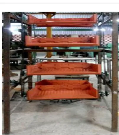
[image:5.595.37.288.200.572.2]Final Assembly of the system is shown in figure 6. The system is tested for the designed load and work satisfactory.
Fig.6. Assembly of the automated shelves system
VI.
Result and conclusion
The automated storage and retrival system for the selected application is designed, analyzed and fabricated. The system is tested and is found to work satisfactorily. It takes twenty five seconds for the shelf to complete one full rotation. The speed of the shelf was found 14.4 cm per second.
In MHS, The automated shelves is an efficient system which will transfer the material from higher to lower level. It can be used in wide applications for material handling for domestic, industrial as well as commercial purpose. It can be easily tailored to the applications individual needs. It optimizes the use of vertical space and also reduces the time and effort needed to bring the items kept at elevated height.
REFERENCES
[1] Sam Flanders, “Industrial Carousels- A Versatile Technolgy for Distribution Applications”, Document #WMC-WP-2883, March 4 2002.
[2] Makato Kanehira, Tomofumi Otani, “Complete Guide to Chain”,(Handbook), U.S Tsubaki, Inc, 1997
© 2017, IRJET | Impact Factor value: 5.181 | ISO 9001:2008 Certified Journal | Page 658 Transportation of Materials To and From
Mezzanine”, Electronic Thesis and dissertations, Paper 1387,(2011)
[4] Brook Crompton, “Brake Motors Catalogue”. 2010E Issue 1.
[5] Aji Roy, “Object Sorting Robotic Arm Based on Colour Sensing”, International Journal of Advanced Research in Electrical, Electronics and Instrumentation Engineering, Vol. 3, Issue 3, March 2014.
[6] JörgOser, Christian Landschützer, “Drive And Motion Design In Material Handling Equipment”
[7] Garg Uttam, BhowadRugved, Rahul Chorghe, Yadav Sachin, “Vertical Material Handling System”, International Journal Of Mechanical Engineering And Technology (IJMET), Volume 6, Issue 2, February 2015
[8] Russell D. Meller∗ and John F. Klote, “Throughput
Model For Carousel/VLM Pods”,ISSN: 0740-817X print / 1545-8830 online,
February 2004
[9] Manas Lad, Prabhat Mahamuni, Prachi Mandve, Savio Sequeira, Sanjay Rukhande, “ Design and Fabrication of Automated Shelves”, IJIRT, 143382, April 2016 | IJIRT | Volume 2 Issue 11 | ISSN: 2349-6002, pg 85-89
[10]Web-Link-
http://www.orientalmotor.com/applications/ conveyor-belt.html
[11]Web-Link, code-for-using-a-tcs3200-with-arduino- and-a-question
[12]Web Link- http://storagemotion.com/
[13]Web-Link-http://www.valinonline.com/images/support_ docs Oriental-Motor-Electromagnetic-Brake-Motors.pdf
[14]WebLink-http://www.dfrobot.com/wiki/index.php/ TCS3200 _Color_Sensor_(SKU:SEN0101)
[15]Web-Link-https://www.arduino.cc/en/Main/arduino Board Uno
![Fig.1.Vertical Carousel Storage System used in industry [1]](https://thumb-us.123doks.com/thumbv2/123dok_us/8178214.809968/1.595.360.529.306.477/fig-vertical-carousel-storage-used-industry.webp)