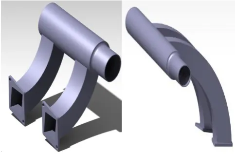
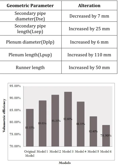
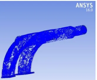
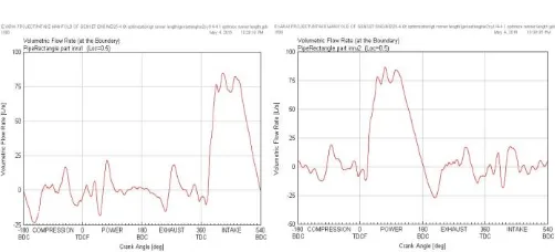
Design, Analysis and Optimization of an Intake Manifold of Two Cylinder Stationary Diesel Engine
Full text
Figure
Related documents
A problemática desta investigação traduz-se no objetivo da Universidade de Aveiro, nas pessoas do investigador, do orientador e do coorientador em cooperação com a Tuna
Using a pair of Casio smart phones, the technology was demonstrated at the 2012 Consumer Electronics Show in Las Vegas to exchange data using light of
At each generation of selection 20 pairs of flies were measured for wing and thorax length in each of the selected inbred lines, and the selection procedure was
Previously, we demonstrated that the immune response against HSV-1 is dependent on TLR2 and TLR9 expression and on IFN gamma production in the trigeminal ganglia (TG) of infected
Analisis ini akan menguji empat hipotesis penelitian yang telah disusun dengan menggunakan perangkat analisis sebagai berikut: Pearson Correlation (mengukur sejauh
Senzorické hodnocení prsní svaloviny zaznamenalo statisticky vysoce průkazný rozdíl (p < 0,01) při hodnocení křehkosti (maso z kusů s delší dobou výkrmy byla hodnocena
Nanosuspension technology can be used to enhance the solubility of the poorly soluble drugs in aqueous as well as lipid media and also to improve the stability
