© 2018, IRJET | Impact Factor value: 6.171 | ISO 9001:2008 Certified Journal | Page 877
EXPERIMENTAL STUDY OF STRUCTURAL BEHAVIOUR OF DOUBLE SKIN
HOLLOW–CFST UNDER AXIAL COMPRESIVE LOADING AT DIFFERENT
HOLLOWNESS RATIOS
Goutam Varma
1,
Dr.Pankaj Singh
2,
Niraj Soni
3,
Kapil Kushwah
4,
Mayur Singi
5,
Vinod Goud
61,3,4,5 Research Scholar S.R.K. University Civil Engineering
2 Professor S.R.K. University Civil Engineering
6 Research Scholar SVCE Civil Engineering
---***---ABSTRACT: The purpose of this experimental study is to investigate the behavior of the double-skinned concrete filled
steel tubular (DSCFT) columns on the strength, stiffness and ductility performance. The diameter-thickness (D/t) ratio and the hollowness ratio were chosen as main parameters in designing the specimens. A total of 36 specimens were tested under axial compressive load. Test results concluded that the DSCFT columns can effectively provide strength and deformation capacity even with a large D/t ratio. We have studied the variation in structural properties of Double Skin Hollow CFST at different hollowness ratios. Total 36 no. of specimens were prepared and tested in axial compressive loading with different hollowness ratio.
INTRODUCTION:
Double-skinned Hollow concrete filled steel tubular (DSH-CFST) columns consisting of two concentric circular thin steel tubes with filler between them have been investigated for different applications the use of fully concrete filled steel tubes (DSH-CFST) has become widespread in the past few decades.
They have Better structural performance than those of bare steel or bare reinforced concrete. The steel hollow section acts as Formwork as well as reinforcement for the concrete. Concrete eliminates or delays the local buckling of steel hollow section, and increases significantly the ductility of the section. DSH-CFST construction has proven to be economic in material as well as providing for rapid construction and thus additional cost savings. In recent years, it was proposed by several researchers that concrete filled double skin steel tubes (DSH-CFST) be studied for their strength as a column or a beam. Advantages of DSH-CFST over CFST include: increase in section modulus; enhancement in stability; lighter weight; good damping characteristics and better cyclic performance. It is expected that the DSH-CFST.
Columns can obtain a higher fire resistance period than the CFST columns, due to the inner tubes of the composite columns being protected by the sandwiched concrete during fire. It is thus expected that concrete filled double skin steel tubes (DSH-CFST) have a potential of being used in building structures Steel members have the advantages of high tensile strength and ductility, while concrete members may be advantageous in compressive strength and stiffness.
A variation of the concrete filled tubular column is the double-skin tubular column (DSH-CFST), consisting of two generally concentric tubes with the space between filled with concrete. To the best knowledge of the authors, such double-skin tubes were first reported in late 1980s (Shakir-Khalil and Illouli 1987). Since then, much research has been conducted on these columns, both on double skin steel tubular columns (Shakir-Khalil 1991; Wei et al. 1995; Yagishita 2000; Zhao et al. 2002; Tao et al. 2003) and double-skin FRP tubular columns (Fam and Rizkalla 2001). The inner void reduces the column weight without significantly affecting the bending rigidity of the section and allows the easy passage of service ducts.
© 2018, IRJET | Impact Factor value: 6.171 | ISO 9001:2008 Certified Journal | Page 878
Double Skin Hollow CFST
In modern structural construction, Double Skin Hollow CFST columns have gradually become a central element in structural systems like buildings, bridges and so forth.
Double Skin Hollow CFST columns have become so widespread owing to their axially compressed nature making them superior to conventional reinforced concrete and steel structural
OBJECTIVES OF THE STUDY
1. The main objective this experimental work is to study structural behavior of double skin hollow CFST in axial compressive loading condition.
2. To compare the structural properties of the two types of Double Skin Hollow CFST and solid CFST. 3. To improve the ductility of Double Skin Hollow CFST to take heavy the earthquake loads.
4. To study the variation in structural properties of Double Skin Hollow CFST at different hollowness ratios
METHODOLOGY
The hollow sections are to be filled with concrete on site. For sections filled under factory conditions, the same basic requirements need to be met; however, the more closely controlled conditions in the factory could have advantages, particularly when high strength concretes are being used. It must be emphasized that the concrete plays an important structural role and it will only do this if a good standard of concrete design, concreting procedure, control and site supervision is used.
In many cases, grout is an acceptable alternative to concrete for filling hollow sections and in most cases the following recommendations also apply to grout filling.
Good control over concrete materials and testing is required, especially for higher strength mixes. The testing of materials for concrete, and of the concrete itself, should be in accordance with the standards and regulations generally accepted or laid down in the country in which the work is to be carried out. General information on concrete and concreting may be found in textbooks on the subject.
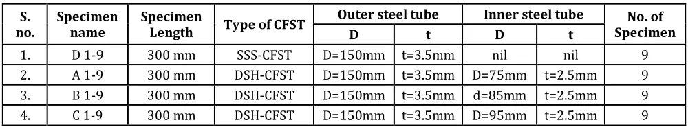
[image:2.596.48.556.493.587.2]In this experimental work we will use the four sizes of steel tubes with following dimensions.
Table no. 1 Specimen Grouping
The concrete should have the following properties:
(i) Sufficient workability to ensure proper compaction.
(ii) Sufficient cohesiveness to reduce the likelihood of segregation and bleeding. (iii) Curing for the specified 28-days
After preparing test specimens we will test them in axial compression testing machine. Then we will draw all the curves on the basis of test results to compare strength of all four types of CFST.
EXPERIMENTAL WORK
The experimental work was carried out in two stages. In first stage, properties of various materials were determined and in second stage cylinder were prepares and tested.
S.
no. Specimen name Specimen Length Type of CFST
Outer steel tube Inner steel tube No. of Specimen
D t D t
© 2018, IRJET | Impact Factor value: 6.171 | ISO 9001:2008 Certified Journal | Page 879
Testing of various materials for parametric study:
1. Cement:
Ordinary Portland cement (Birla uttam OPC-43 grade cement) having average compressive strength (7days) 45.32 N/mm2
used. Compressive strength of cement was determined as per procedure given in Indian Standard (IS) code.
2 Sand:
The coarse sand obtained from Narmada River, which is normally used in Indore region has been used in this study. The following of sand were determined as per procedure given in IS code.
Course aggregate
Course aggregate (crushed ballast) passing through 40mm sieve and retained on 4.75 sieve were used in this study. Following properties of aggregate were determined as per procedure given in IS code.
Summary of material properties
(1) Cement:
Since, Portland pozzulana cement gives low rate of hydration hence, in present study ordinary Portland cement (Birla uttam OPC-43 grade cement) having average compressive strength (7 days)of 45.32 N/mm2 is used.
(2) Coarse sand:
Sand used in present study is fineness modulus of 2.75 and specific gravity of 3.45.
(3) Coarse aggregate:
Locally available having fineness modulus of 5.6 and specific gravity.
(4) Water:
Waterused for the purpose of mixing and curing.
(5) Mix proportion (M20)
Testing of cube:
Six concrete cubes were prepared mix proportion 1:2.21:4.02and water-cement ratio 0.51. Cubes were cured in water and 28 days compressive strength was determine by digital compressive strength testing machine.
Table no. 2 Test results Compressive strength of Cube
S.no. Average Compressive strength (N/mm2 ) 7 days 28 days
1. M-20 grade concrete for trial 14.73 22.06
2. M-20 grade concrete for filling in tubes 14.25 22.3
Testing of steel:
To determine tensile strength of steel tubes a tensile test has been done on basis of the guide lines given by IS-1977 code for steel testing.
Table 2 Results of tensile test
The average tensile strength is found as 502.855 N/mm2
Serial no. Specimen no. Tensile strength in N/mm2 % elongation
1. S-1 548.57 23.06
2. S-2 457.12 22.3
© 2018, IRJET | Impact Factor value: 6.171 | ISO 9001:2008 Certified Journal | Page 880
[image:4.596.36.566.121.248.2]Testing of Specimen
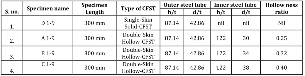
Table 3 Details of specimens
Total 36 no. of specimen has been prepared.
Table 4 (for h/t, d/t, and hollow ness ratios)
Testing of specimen under axial Compressive loading:
Concrete filled steel tubes under axial loading condition the specimen were casted and tested for axial compression testing machine. Load is applied on both steel and concrete core through thick steel plate. The experimental setup is shown in photograph below, two dial gauge (DL1 & DL2) are used to record the axial deformation valve at a particular load and
D-Mac gauge is also used to determine axial deformation and to verify the reading of dial gauges.
The test was done by keeping the specimen centrally on the location marks of compression testing machine (2000 KN capacity) and load was applied gradually, uniformly and without jerk. The rate of loading was kept constant and reading was taken for every 50 KN incremental. The load was increased at this rate until the specimen failed
S. no. Specimen name Specimen Length Type of CFST Outer steel tube Inner steel tube ness ratio Hollow
D t D t
1. D 1-9 300 mm Single-Skin Solid-CFST D=150mm t=3.5mm nil nil Nil
2. A 1-9 300 mm Hollow-CFST D=150mm Double-Skin t=3.5mm D=75mm t=2.5mm 0.25
3. B 1-9 300 mm Hollow-CFST Double-Skin D=150mm t=3.5mm d=85mm t=2.5mm 0.32
4. C 1-9 300 mm Hollow-CFST D=150mm Double-Skin t=3.5mm D=95mm t=2.5mm 0.40
S. no. Specimen name Specimen Length Type of CFST
Outer steel tube Inner steel tube Hollow ness ratio
h/t d/t h/t d/t
1. D 1-9 300 mm Single-Skin Solid-CFST 87.14 42.86 nil nil Nil
2. A 1-9 300 mm Hollow-CFST Double-Skin 87.14 42.86 122 30 0.25
3. B 1-9 300 mm Hollow-CFST Double-Skin 87.14 42.86 122 34 0.32
[image:4.596.39.559.299.429.2]© 2018, IRJET | Impact Factor value: 6.171 | ISO 9001:2008 Certified Journal | Page 881
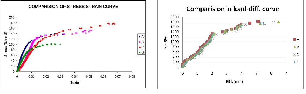
RESULTS AND DISCUSION
Comparison b/w stress strain curve of all four types of CFST (A, B, C, D) Comparison b/w load-diff. curve of all four types of CFST (A, B, C, D)
COMPARISION OF STRESS STRAIN CURVE
0 20 40 60 80 100 120 140 160 180 200
0 0.01 0.02 0.03 0.04 0.05 0.06 0.07 0.08
Strain
S
tr
e
s
s
(
N
/m
m
2
)
A B C D
[image:5.596.42.558.268.427.2]
Results summary
Table 5 for axial load
Table 6 for Compressive stresses S.
no. Specimen name Specimen details Hollowness ratio
Load Obtained Experimentally
in KN
Load Obtained from K.Kwedaras
equation in KN
Percentage deviation
1. D Single-Skin Solid-CFST nil 1770 931 52%
2. A Hollow-CFST Double-Skin 0.25 1800 959 53%
3. B Hollow-CFST Double-Skin 0.32 1810 944 52%
4. C Hollow-CFST Double-Skin 0.40 1830 924 50%
S. no. Specimen name Specimen details Hollowness ratio Stress in N/mm2 % increase in stress w.r.t. SSS-CFST
1. D Single-Skin Solid-CFST nil 100 -
2. A Hollow-CFST Double-Skin 0.25 137 37%
3. B Hollow-CFST Double-Skin 0.32 151 51%
© 2018, IRJET | Impact Factor value: 6.171 | ISO 9001:2008 Certified Journal | Page 882
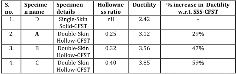
Table 7 for Ductility
CONCLUSIONS:
1. Superposing the concrete and steel strength can predict the ultimate axial strength of DSH-CFST Conservatively. It is illustrated that steel tube can improve the confinement of the concrete, and the In-filled concrete can delay the occurrence of local buckling of the steel tube with a large D/T ratio.
2. The DSCFT columns can have an optimal strength performance if the applied axial load is less than 30%, 38%, 45%, and 36%, the axial capacity for the tube type A, B, C, and D, respectively.
3. It concluded that the inner tube acts as if it stands alone, but can develop its full yielding strength for the presence of the sandwiched concrete; and the outer tube and sandwiched concrete exhibit the same behavior as a fully filled CFST column without the presence of the voids. In other words, the confined state of the concrete is the same as that in the CFST column if the hollow section ratio is not too large.
4. It concluded that on increase hollowness ratio axial compressive stress and ductility is increased in comparison of solid steel tube
5. Performance of CFSTs In linear range in compressive loading can be arranged in decreasing order on the basis of test results as follows A>D>B>C
6. Performance of CFSTs In non linear range in compressive loading can be arranged in decreasing order on the basis of test results as follows C>B>A>D
7. It is concluded that Performance of Double-Skin Hollow-CFST A at hollowness ratio 0.25 is better than all types of CFSTs, on further increasing hollowness ratio Performance of Double-Skin Hollow-CFSTs, B and C is lowers in linear range and increased in non linear range.
REFERENCES:
1. SEWEL, J. S. Columns for buildings. Engineering News, 1992, 48(17), p. 36–39
2. ZHONG, S.; and ZHANG S. M. A new method from China to determine load-carrying capacity for CFST members. In Proc of the Engineering Foundation Conference: Composite Construction in Steel and Concrete II, Potosi, Missouri, USA, 14-19 June 1998. Ed by D. Darwin and D. Dale Buckner, p. 499–511.
3. ZHONG, S. Application and research achievement of concrete filled steel tubular (CFST) structures in China. In Proc of the 8th International Conference on Steel Concrete Composite and Hybrid Structures, Harbin, China, 12–14 Aug 2006, p. 24–29
4. ZHONG, S.; and ZHANG, S. Application and development of concrete-filled steel tubes (CFST) in high rise buildings. Advances in Structural Engineering, 1999, 2(2), p. 149–159.
5. ZHONG, S.; CHENG, H. T.; and ZHANG S. The continuity of behaviors for circular, square and octagonal forms for concrete filled steel tube (CFST) members under axial compression.
S.
no. Specimen name Specimen details Hollowness ratio Ductility % increase in Ductility w.r.t. SSS-CFST
1. D Single-Skin
Solid-CFST nil 2.42 - 2. A Double-Skin
Hollow-CFST 0.25 3.12 29% 3. B Double-Skin
Hollow-CFST 0.32 3.56 47% 4. C Double-Skin