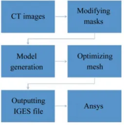
http://dx.doi.org/10.4236/jsea.2015.81001
The Establishment of Three-Dimensional
Model of Human Knee Joint
Ziyue Liu, Fuzhong Wang
Department of Physics, Tianjin Polytechnic University, Tianjin, China Email: [email protected]
Received 13 December 2014; revised 28 December 2014; accepted 6 January 2015
Copyright © 2015 by authors and Scientific Research Publishing Inc.
This work is licensed under the Creative Commons Attribution International License (CC BY).
http://creativecommons.org/licenses/by/4.0/
Abstract
Objective: To discuss a method to establish a three-dimensional model of healthy human knee joint, which can be used for further knee joint biomechanics analysis and simulation. Methods: CT scan and medical image three-dimensional reconstruction software (Mimics) were used to obtain the knee joint three-dimensional finite element model (FEM) according to reverse engineering theory. Results: FEM of knee joint with complete bone structure was established by Mimics. Conclusion: Three-dimensional FEM was established according to CT images exports as IGES file. The model can be used for knee joint biomechanics finite element analysis to provide references and propos- als for the clinical diagnoses of knee joint illness, and the design of artificial knee joint prosthesis.
Keywords
Knee Joint, Mimics, Three-Dimensional Model
1. Introduction
re-Computer (CPU: Intel Core™ i5-2430 2.40 GHz*2, RAM: 8.00 GB, GPU: GT-540M, OS: win7), CT images, Mimics medical image three-dimensional rebuilding software, Ansys 11.0 finite element analysis software. The CT images come from the database of visible human project of the US national library of medicine. 800 1 mm scanned healthy woman lower limbs CT images were downloaded as Dicom format. Mimics was programmed in 1992 and widely used in digital medical field. The initial propose was to apply CT scan images in rapid pro-totyping manufacturing. With the growing improvement, it is now widely used in Computer-Aided Mechanical Engineering, including medical three-dimensional modeling based on medical images, computer-aided design, finite element and hydromechanics analysis, rapid prototyping manufacturing, visual operation planning, anth-ropotomy measurement analysis, etc. Ansys is a powerful engineering stimulation software widely used in many fields including structural mechanics, multiphysics, fluid dynamics, explicit dynamics, electromagnetics, and hydrodynamics.
2.2. Experiment Method
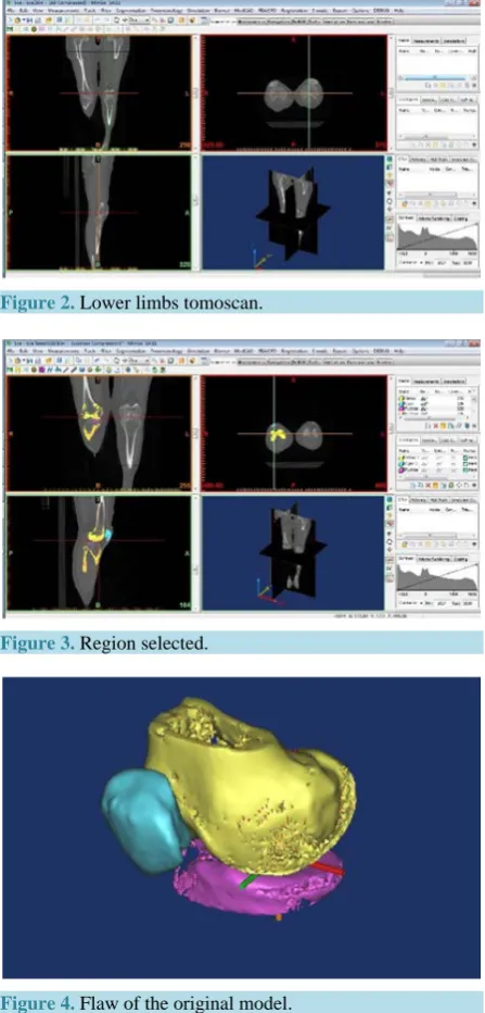
1) Input the data of the model: import the 800 Dicom CT images to Mimics. Original axial view, coronal plane and vertical plane from the scanned data was observed as Figure 2.
2) Rebuild the three-dimensional model: image thresholding segmentation was the first step of the modeling procedure and mask was obtained. Since it is the knee joint that need modeling, we selected the object region by “region growing” in the toolbar, shown as Figure 3, distal femur, patella, tibial plateau of the right leg was se-lected. The default gray value of the bone is only reference, the auto generated mask may not cover all the bone in the region. There would be a lot of small cracks, bumps and pits, shown as Figure 4. We need to modify the mask until all the area is covered completely. At last “smooth object” option was used to optimize the model produced, the knee joint model is shown as Figure 5.
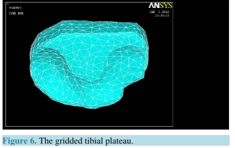
3) Preliminary treatment of the finite element analysis: before the analysis, the model needed to be meshed to finite element grid model, this was obtained by FEA module in Mimics. The grid was optimized by remesh module. The finite element model (Figure 6) was obtained for further research.
4) Apply material properties to the model:
The parameters in Table 1 were preferred from previous literature [5].
[image:2.595.250.378.573.702.2]5) Loads and boundary conditions: approximately 40% of the body weight is applied to each knee when standing. In this paper, we consume the total weight is 60 Kg, so 235 N was applied on the mechanical axis of
Figure 2. Lower limbs tomoscan.
[image:3.595.201.427.560.707.2]Figure 3. Region selected.
Figure 4. Flaw of the original model.
Figure 6.The gridded tibial plateau.
Table 1. Material properties of the components of the knee joint model.
Material Young’s modulus (MPa) Poisson’s radio (μ)
Femur 12,000 0.3
Tibia 6900 0.49
Patella 12,000 0.3
the top femur. The boundary condition was set that tibia and femur were kept fixed in all direction. The model was solved by Ansys 11.0.
3. Results
In this paper, we established the model of a healthy human knee joint, and conducted biomechanics analysis to it.
Figure 7 shows the Von Mises stress distribution of the tibial plateau.
Von Mises stress was chosen to evaluate the stress index in this analysis. It is a combined stress defined ac-cording to the 4th strength theory reflecting the average stress level each dot inside the material, and one of the most objective indices in finite element analysis [5]. The maximum of the Mises stress locates in the contact re-gion of femoral condyle and tibial plateau. The maximum stress is 25 MPa at the edge of the tibial plateau. The result is corresponded with clinical cases that injury of inner side meniscus and tibial plateau is more common and the maximum of the Von Mises stress accord with other researches [6]. This means that the model estab-lished can be used to present the authentic status of human knee joint.
4. Discussion
In this research, we built the knee joint model including distal femur, patella, and tibial plateau precisely based on the CT images of human lower limbs. This method can be used to establish knee joint model fast and accu-rately, and the file is suitable to directly transfer to finite element analysis software (Ansys) for biomechanics simulation.
However, the soft tissue of the knee joint (ligament, joint capsule, synovial fluid, etc.) was not obtained. This is due to the fact that CT image cannot provide the soft tissue outline as clear as the bone tissue [7]. To accom-plish this part, one way is to depict the soft tissue according to the anatomy structure of knee joint on the CT- conducted model which may contribute to the untruthfulness of the model because of the lack of accuracy. Another method is to use MRI image which can show soft tissue clearly [8]. We will integrate our present work with MRI image in the future.
[image:4.595.197.433.86.235.2]Figure 7. The Von Mises stress distribution of the tibial plateau.
traditional specimen test and clinical research cannot solve. Since 1960s, finite element method has widely ap-plied in biomechanics analysis. It had successfully utilized in hip joint, knee joint, spine, shoulder, etc. [10]. The finite element analysis is a strong addition and useful tool in the study of biomechanics and it will become the development trend in the future.
References
[1] Zhang, S.N. and Lu, A.Y. (2005) Animal Model of Musculoskeletal Motion Injury Research. Chinese Journal of Sports Medicine, 31, 185-188.
[2] Zhang, H.P. and Song, J.R. (2010) Establishment and Application of Animal Experimental Models of Acute Skeletal Muscle Injury. Journal of Clinical Rehabilitative Tissue Engineering Research, 11, 458-463.
[3] Zhao, T., Weng, L., You, Y.-H., et al. (2013) The Appearance of X-Ray and MR Imaging in Osteochondral Fracture of Knee Joint after Acute Injury. Chinese Journal of Radiology, 37, 985-988.
[4] Teng, Y., Wang, Z., Li, D.C., et al. (2008) Fabrication of Custom-Made Artificial Semi-Knee Joint Based on Rapid Prototyping Technique: Three-Dimensional Reconstruction of Femoral Condyle. Chinese Journal of Reparative and Reconstructive Surgery, 41, 257-260.
[5] Niu, Y.F. (2012) The Impact of Cartilage Hardening of the Knee Articular Cartilage to the Stress Distribution of Knee Joint. M.Sc. Thesis, Tianjin Polytechnic University, Tianjin.
[6] Chantarapanich, N., Nanakorn, P., Chernchujit, B., et al. (2009) A Finite Element Study of Stress Distributions in Normal and Osteoarthritic Knee Joints. Journal of the Medical Association of Thailand, 17, 223-226.
[7] Gíslason, M.K., Stansfield, B. and Nash, D.H. (2010) Finite Element Model Creation and Stability Considerations of Complex Biological Articulation: The Human Wrist Joint. Medical Engineering and Physics, 34, 246-249.
[8] Luring, C., Hufner, T., Perlick, L., et al. (2006) The Effectiveness of Sequential Medial Soft Tissue Release on Coronal Alignment in Total Knee Arthroplasty: Using a Computer Navigation Model. Journal of Arthroplasty, 21, 428-434.
http://dx.doi.org/10.1016/j.arth.2005.05.031
[9] Manda, K., Ryd, L. and Eriksson, A. (2011) Finite Element Simulations of a Focal Knee Resurfacing Implant Applied to Localized Cartilage Defects in a Sheep Model. Journal of Biomechanics, 44, 794-801.
http://dx.doi.org/10.1016/j.jbiomech.2010.12.026