ORIGINAL RESEARCH ARTICLE
DESIGN OF A PNEUMATICALLY DRIVEN ROBOTIC WORKBENCH FOR REHABILITATION
1,2
Roberta Goergen,
2Marcia Regina Maboni Hoppen Porsch,
2Antonio Carlos Valdiero,
2Luiz Antônio Rasia,
3Maurício Oberdörfer,
3Jocarly Patrocínio de Souza
and
4Rogério Sales Gonçalves
1
Federal Institute of Education, Science and Technology Farroupilha,
Campus
Panambi, R. Erechim, 860 -
Planalto, Panambi - RS/Brazil
2
Regional University of the Northwest of the State of Rio Grande do Sul, R. Pref. Rudi A. Franke,
540 - Arco-Íris, Panambi - RS/Brazil
3
University of Passo Fundo, BR 285, São José, Passo Fundo/RS, Brazil, CEP: 99052-900
4
Federal University of Uberlândia/Brazil, School of Mechanical Engineering, Av. João Naves de Ávila 2121
Campus Santa Monica CX 593, Uberlândia – MG/Brazil
ARTICLE INFO ABSTRACT
This paper addresses the application of robots to aid in the physical rehabilitation of patients. The objective is to present the design of a pneumatically driven robotic workbench with force control for rehabilitation of upper and lower limbs. Recently, the research in the mechatronic systems field is being developed to assist the physical rehabilitation of people who have suffered some form of serious physical injury. Robotic manipulators make it possible to carry out tasks repeatedly in a controlled and reliable way, which has been demonstrated in the literature as a determinant factor for the increase of the motor skill and improvement in the performance of functional activities. For interaction between the robot and the human, pneumatic actuators with controllable stiffness are used to avoid injury to the patient and damage to the equipment. It is perceived that due to the compressibility of the air, it is more advantageous and safer in applications involving the risk of accidents and the need to limit the forces of interaction with the environment. The chosen methodology consists of the analysis of needs, design and modelling of systems. This work aims to contribute to the development of innovative robotic manipulators used in upper and lower limb rehabilitation therapies.
Copyright © 2018,Roberta Goergen et al. This is an open access article distributed under the Creative Commons Attribution License, which permits unrestricted
use, distribution, and reproduction in any medium, provided the original work is properly cited.
INTRODUCTION
The science of rehabilitation shows that repeated movements of human limbs can help the patient regain function in the injured limb. There are three types of mechanical systems used for movement rehabilitation: robots, cable-based manipulators, and exoskeletons (Gonçalves and Carvalho, 2012; Barbosa et al., 2018). Advances in the technologies applied to robotics and automation are increasing and their applications in the medical sectors have increased in the last decades.
*Corresponding author:1,2Roberta Goergen
1Federal Institute of Education, Science and Technology Farroupilha, Campus Panambi, R. Erechim, 860 - Planalto, Panambi - RS/Brazil
2Regional University of the Northwest of the State of Rio Grande do Sul, R. Pref. Rudi A. Franke, 540 - Arco-Íris, Panambi - RS/Brazil
The robots are now a useful tool in the rehabilitation of upper and lower limbs. This fact stimulates the development of new structures. In this paper, the major contribution is the application of pneumatic robots to aid in the physical rehabilitation of patients. The main objective of this work is to develop the simple design and low cost of a pneumatically driven robotic workbench with force control for rehabilitation of upper and lower limbs. The Technology Assistive has contributed immensely to the design and deployment of interfaces to aid physically handicapped people to combat their disabilities. The alternate interfaces assist individuals in leading a normal life and perform expected activities. (Dubey
et al. 2014). Today pneumatic drives are widely used to
perform various industries motion tasks. They have the
ISSN: 2230-9926
International Journal of Development Research
Vol. 08, Issue, 08, pp. 22408-22413, August,2018
Article History:
Received 17th May, 2018
Received in revised form 21st June, 2018
Accepted 18th July, 2018 Published online 31st August, 2018
Available online at http://www.journalijdr.com
Key Words:
Rehabilitation Robots; Force Control; Pneumatic Actuators; Assistive Technology.
Citation: Roberta Goergen, Marcia Regina Maboni Hoppen Porsch, Antonio Carlos Valdiero, Luiz Antônio Rasia, Maurício Oberdörfer, Jocarly Patrocínio de Souza and Rogério Sales Gonçalves. 2018. “Design of a pneumatically driven robotic workbench for rehabilitation”, International Journal of Development Research, 8, (08), 22408-22413.
advantages of low purchase price and robust design, but show high energy consumption in comparison with electric drives. Existing energy saving measures lead to the reduction of energy consumption, but at the same time they cause the increase of the life cycle costs. All in all, the selection of pneumatic drives has been done regarding their functionality, efficiency and costs. In Rakova and Weber (2016) the novel exonomy approach is presented for the selection of the most cost-effective pneumatic drive solution. The dynamic model of a force controlled system depends not only on the actuator but also on the manipulated object. Generally, the object dynamics are unknown and frequently change, and it therefore is difficult to identify the actual dynamics of the system. To enhance the controller performance for the pneumatic system, Kaitwanidvilai and M. Parnichkum (2005) proposed a hybrid adaptive neuro-fuzzy model. Ben-Dov and Salcudean (1995) used graphite piston glass cylinders to minimize the effects of friction in power control applications of a special pneumatic actuator for applications in robotic claws because friction dynamics is very important in a pneumatically driven robotic model. The paper is organized in the following sequence of sections: materials and methods are described, the brief description of rehabilitation need analysis and state-of-the-art survey of the main results obtained from the use of robotic manipulators for rehabilitation are presented, the results with the proposed design of a pneumatically driven robotic workbench for rehabilitation and experimental identification of friction dynamics in the pneumatic actuator are shown. Lastly, remarking conclusions are summarized.
MATERIALS AND METHODS
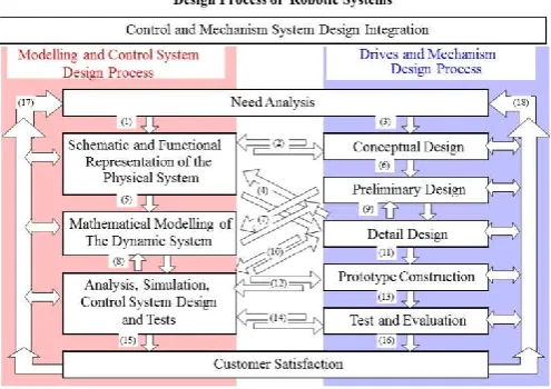
In order to increase the probability of success of new pneumatically driven robotic workbench with force control for rehabilitation, the design process was planned carefully and executed systematically. In particular, an engineering design method must integrate the many different aspects of designing in such a way that the process becomes logical and comprehensible (Valdiero and Rasia, 2016). To that end, the design process of robotic system must be broken down, first into phases and then into distinct steps, each with its own working methods. It is with these aims in mind that several authors (Pahl and Beitz, 2013; Valdiero and Rasia, 2016) split the design process into main phases that can be translated as Need Analysis; Conceptual Design; Preliminary Design; Detail Design; Prototype Construction; Test and Evaluation; and Final Documentation of Robot Drives and Mechanism as shown in Figure 1. According to Valdiero and Rasia (2016), from the Needs Analysis phase, the modelling and controller design methodology can be divided into the three main phases proposed by Nise (2007) and illustrated in Figure 1: schematic and functional representation of the physical system; mathematical modelling; and analysis, simulation, controller design and tests. Schematic and functional representation of the physical system (5) is based on the requirements and performance specifications (1) required of the controller, the conceptual design of the mechanical system (2) as well as detailed information (4) of the mechanical components, the description of the physical system. A functional block diagram or a schematic representation of the electrical and mechanical components can be constructed for better visualization. This phase results in knowledge of the physical system. Mathematical modelling of the dynamic system is formulated from the knowledge of the physical system (5), physical laws (from Kirchhoff, Newton, energy balance, among others) and
[image:2.595.310.558.436.611.2]treatment tools (linearization, Laplace transform, among other mathematical methods), obtaining the system representations in the state variables form, non-linear and linear models, transfer functions, among other representation forms of the dynamic behavior of the system (flow-signal diagram, etc.). This phase interacts with the preliminary design (7) of the machine elements and obtains an estimate of the nominal parameters of the modeled system. Analysis, simulation, controller design and tests steps have as input the modelling (8) obtained in the previous phase, where can be used linear and non-linear control techniques, sensitivity analysis, stability analysis, CACSD (Computer Aided Control System Design) tools and test instrumentation in order to obtain a controller with satisfactory and safe performance. This phase has relations with the detailed design (10), the construction (12) and the prototype tests (14), through which the system parameters are measured, the sensors and other physical components of the control system are specified, besides the controller gains settings. That is, at this stage the development, implementation and validation of the proposed controllers takes place. If the test results are satisfactory for both the controller (15) and the mechanical (drives and mechanism) system (16), then the user-field tests are performed, and in this final phase, indicators of customer satisfaction are important information, which must be feedback into the process, (17) and (18), for design improvements. The activities are being developed at the Innovation Center for Automatic Machines and Servo Systems (NIMASS/UNIJUÍ Campus Panambi), which has adequate computational and experimental infrastructure for the construction of a bench of tests to verify and to validate the performance of the modelling and force control on pneumatic actuators.
Figure 1. Design Methodology of smart machines and robots (adapted from Valdiero and Rasia, 2016)
Need Analysis of Rehabilitation and Survey: Rehabilitation medicine aims to treat or lessen the disabilities caused by chronic diseases, neurological sequelae, traffic and work accidents. Rehabilitation is a global and dynamic process oriented towards the physical and psychological recovery of the person with disabilities, with a view to their social reintegration (Carvalho and Gonçalves, 2010). The Figure 2 illustrates the main motions at the level of the shoulder. During the last two decades, the use of robotic instruments for upper-limb rehabilitation has increased as robot-based rehabilitation provides an accurate evaluation of motor recovery and automates simple tasks that burden health professionals such as physiotherapists and occupational therapists.
Figure 2. Upper-limb rehabilitation movements: (a) Vertical flexion-extension, (b) Horizontal flexion-extension, (c) Adduction
abduction. Adapted Hernandez et al
Nowadays, as the number of people that require physical rehabilitation has increased, the need has arisen to create low cost home-based robotic instruments that are simple, acceptable and provide easy monitoring, smart assessment, and adaptable training (Lioulemes et al., 2017)
decade, several lower-limb rehabilitation robots have been developed to restore mobility of the affected limbs. These systems can be grouped according to the rehabilitation principle they follow in Figure 3. During the
the use of robotic instruments for upper-limb rehabilitation has increased as robot-based rehabilitation provides an accurate evaluation of motor recovery and automates simple tasks that burden health professionals such as physiotherapis occupational therapists. Nowadays, as the number of people that require physical rehabilitation has increased, the need has arisen to create low-cost home-based robotic instruments that are simple, acceptable and provide easy monitoring, smart assessment, and adaptable training (Lioulemes
Over the last decade, several lower-limb rehabilitation robots have been developed to restore mobility of the affected limbs. These systems can be grouped according to the rehabilitation principle they follow in Figure 3.
Hernandez et al. (2017) present an optimized design of a cable driven parallel manipulator that is intended in rehabilitation or exercise of patients with shoulder problems like illness, traumatic events or for the elderly who need to exercise their limbs. Cable based parallel manipulators have characteristics that make them suitable for rehabilitation exercise purposes like large workspace, re-configurable architecture, portability and low cost. Plitea et al. (2017) propose a nove
parallel robot design, whose name is ASPIRE. A simple but effective solution for shoulder rehabilitation. Kinematics and workspace are analyzed as well as motion simulations are thoroughly presented to show the feasibility and effectiveness of the proposed solution. Guo showed the design of optimize structure for the external skeletal upper limb rehabilitation robot to assist the stroke patients to recovery the motion
22410 International Journal of Develop
limb rehabilitation movements: (a) Vertical extension, (c)
Adduction-et al. (2017)
Nowadays, as the number of people that require physical rehabilitation has increased, the need has arisen to create
low-based robotic instruments that are simple, acceptable and provide easy monitoring, smart assessment, and ., 2017). Over the last limb rehabilitation robots have been developed to restore mobility of the affected limbs. These systems can be grouped according to the rehabilitation During the last two decades, limb rehabilitation has based rehabilitation provides an accurate evaluation of motor recovery and automates simple tasks that burden health professionals such as physiotherapists and occupational therapists. Nowadays, as the number of people that require physical rehabilitation has increased, the need has based robotic instruments that are simple, acceptable and provide easy monitoring, smart
sment, and adaptable training (Lioulemes et al., 2017). limb rehabilitation robots have been developed to restore mobility of the affected limbs. These systems can be grouped according to the rehabilitation
n optimized design of a cable driven parallel manipulator that is intended in rehabilitation or exercise of patients with shoulder problems like illness, d to exercise their limbs. Cable based parallel manipulators have characteristics that make them suitable for rehabilitation exercise purposes configurable architecture, portability propose a novel spherical parallel robot design, whose name is ASPIRE. A simple but effective solution for shoulder rehabilitation. Kinematics and workspace are analyzed as well as motion simulations are thoroughly presented to show the feasibility and effectiveness Guo showed the design of optimize structure for the external skeletal upper limb rehabilitation robot to assist the stroke patients to recovery the motion
function, according with the physiological structure of the human body. This rehabilitation robot can be used by patients, not only in the hospitals for rehabilitation, but also be used when patients are not in hospitals, which bring great convenience for hemiplegic patients.
model of the human knee, based on me
provide orthopedic surgeons information that relates forces at the anterior cruciate ligament graft (ACL) with its fixing position, was developed by Ponce
position must be defined at the preoperative planning p the ligament replacement surgery. Wu
their paper a 3-degree-of-freedom (3DOF) lower limb rehabilitation robot (LLRR) has been developed for the motion recovery, with aiming to assist stroke patients who suffer from motor dysfunction after stroke and reduce the stress of physiotherapists. Kweon and Kim proposed a new lower limb rehabilitation platform for tailor
Neuroex system working on a lower limb rehabilitation.
Figure 3. Robotic system types for lower treadmill gait trainers, (b) foot
overground gait trainers, (d) stationary gait and ankle trainers Adapted Díaz
Existing control techniques for
ignore robot dynamics by assuming a perfect inner control loop or are limited to rigid-joint robots. The dynamic stability of compliantly-actuated rehabilitation robots, consisting of the dynamics of both robot and compliant
theoretically grounded. In this way Xiang
presented an iterative learning impedance controller for rehabilitation robots driven by series elastic actuators (SEAs), where the control objective is specified as a desired impedan model. Many researchers have done work on pneumatic
International Journal of Development Research, Vol. 08, Issue, 08 pp. 22408-22413, August
function, according with the physiological structure of the ehabilitation robot can be used by patients, not only in the hospitals for rehabilitation, but also be used when patients are not in hospitals, which bring great convenience for hemiplegic patients. A static and spatial model of the human knee, based on mechanism theory, to provide orthopedic surgeons information that relates forces at the anterior cruciate ligament graft (ACL) with its fixing position, was developed by Ponce et al. (2017). This fixing position must be defined at the preoperative planning phase of the ligament replacement surgery. Wu et al. (2016) show in freedom (3DOF) lower limb rehabilitation robot (LLRR) has been developed for the motion recovery, with aiming to assist stroke patients who suffer from nction after stroke and reduce the stress of Kweon and Kim proposed a new lower limb rehabilitation platform for tailor-made exercise planning. The Neuroex system working on a lower limb rehabilitation.
Figure 3. Robotic system types for lower-limb rehabilitation: (a) treadmill gait trainers, (b) foot-plate-based gait trainers, (c) overground gait trainers, (d) stationary gait and ankle trainers
Adapted Díaz et al. (2017)
Existing control techniques for rehabilitation robots commonly ignore robot dynamics by assuming a perfect inner control joint robots. The dynamic stability actuated rehabilitation robots, consisting of the dynamics of both robot and compliant actuator, is not theoretically grounded. In this way Xiang et al. (2017) presented an iterative learning impedance controller for rehabilitation robots driven by series elastic actuators (SEAs), where the control objective is specified as a desired impedance Many researchers have done work on pneumatic
[image:3.595.324.549.284.618.2]robotic systems for rehabilitation. The pneumatic technology can potentially meet the requirements of rehabilitation robots because they have a high power-to-weight ratio, are mechanically compliant because of the inherent compliance of air, and are force controllable (Morales et al.
et al. 2010).
RESULTS
[image:4.595.308.562.53.152.2]The proposed design foresees the programming of the reference movement trajectories by a physiotherapist, in addition to the appropriate limits for the load forces applied to the limbs during the exercises. As seen from Figure 4, the robotic system for rehabilitation of upper and lower limbs is composed of following components: mechanism, pneumatic system and control system.
Figure 4. The pneumatically driven robotic workbench with force control for rehabilitation of upper and lower limbs
The control system consists of hardware, software, sensors and man-machine interface devices, which allow the implementation of control strategies, operation commands and data acquisition. The mechanism consists of a set of rigid links joined by revolute joints and mounted on a fixed base in the chair, whose function is to perform the desired movements in the rehabilitation exercises. Figures 5 and 6 show the simple design of a pneumatically driven robotic workbench for rehabilitation of upper and lower limbs that it was designed on CAD (Computer Aided Design) software.
each mechanism joint is performed by a pneumatic servo positioner comprising a double-acting cylinder and simple rod, and a five-way directional servo valve.
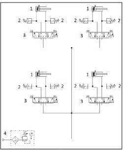
Figure 7 presents the representation of the pneumatic scheme of the robot, designed according to ISO 1219
2012). Table 1 describes the basic elements of the pneumatic robot drive system, according to the numerical indication of the Figure 6. For each limb i (upper or lower) to be exercised with an angular movement i of the mechanism, it is necessary to apply a load force fLi provided by the pneumatic system. The mechanical system of the robotic workbench is shown in Figure 4, where the main loads and parameters involved in each limb rotation dynamics are gravity torque
fLi, the moment of inertia I0i of the rotating mass (mechanism and limb) around the rotation axis, the angular acceleration of the platform and the distance r from the turning center to the point of application of the force. Applying the sum of the torques (∑Toi), we have Equation (1).
22411 Roberta Goergen et al.
robotic systems for rehabilitation. The pneumatic technology can potentially meet the requirements of rehabilitation robots weight ratio, are cause of the inherent compliance of
et al., 2011; Wolbrecht
[image:4.595.306.556.195.305.2]The proposed design foresees the programming of the reference movement trajectories by a physiotherapist, in appropriate limits for the load forces applied to the limbs during the exercises. As seen from Figure 4, the robotic system for rehabilitation of upper and lower limbs is composed of following components: mechanism, pneumatic
Figure 4. The pneumatically driven robotic workbench with force control for rehabilitation of upper and lower limbs
The control system consists of hardware, software, sensors and machine interface devices, which allow the rategies, operation commands and The mechanism consists of a set of rigid links joined by revolute joints and mounted on a fixed base in the chair, whose function is to perform the desired movements in s 5 and 6 show the simple design of a pneumatically driven robotic workbench for rehabilitation of upper and lower limbs that it was designed on The actuation of each mechanism joint is performed by a pneumatic servo acting cylinder and simple rod,
Figure 7 presents the representation of the pneumatic scheme of the robot, designed according to ISO 1219-1 standard (ISO, basic elements of the pneumatic robot drive system, according to the numerical indication of (upper or lower) to be exercised of the mechanism, it is necessary provided by the pneumatic system. The mechanical system of the robotic workbench is shown in Figure 4, where the main loads and parameters involved in each limb rotation dynamics are gravity torque Tgi, load force ating mass (mechanism and limb) around the rotation axis, the angular acceleration
from the turning center to the point of application of the force. Applying the sum of the
[image:4.595.37.291.244.395.2]Figure 5. Robot prototype design with pneumatic actuation for lower limb rehabilitation
Figure 6. Robot prototype design with pneumatic actuation for upper limb rehabilitation
Figure 7. Pneumatic circuit of the robotic workbench
i oi gi Li
oi
r
f
T
I
T
In that manner, we have Equation (2), which represents the dynamics of the rotating mechanism coupled with pneumatic actuator.
pi Ligi i
oi
T
r
f
r
F
I
where Mi is the displaced mass in pneumatic actuator, the cylinder piston acceleration,
et al. Design of a pneumatically driven robotic workbench for rehabilitation
Robot prototype design with pneumatic actuation for lower limb rehabilitation
Robot prototype design with pneumatic actuation for upper limb rehabilitation
Pneumatic circuit of the robotic rehabilitation workbench
………..(1)
In that manner, we have Equation (2), which represents the dynamics of the rotating mechanism coupled with pneumatic
atri i
i
y
F
M
..…………(2)is the displaced mass in pneumatic actuator,
y
i is the cylinder piston acceleration, Fpi is the pneumatic force [image:4.595.308.559.336.642.2]given by Equation (7), and Fatri is the friction force in pneumatic actuator. The kinematic relation between linear movement yi by the pneumatic actuator rod and the angular movement i by the rotating platform can be obtained through the methodology proposed by Valdiero (2012), and is shown in Equation (3):
i i
ii i i i i
i L L L L L
y 2 1 2 3
2 2
1 2 cos
)
(
……..(3)where the constructive parameters L1i, L2i , L3i and i are described in detail in Valdiero (2012). Pneumatic force Fpi is each pneumatic actuator and it is given by Equation (4):
bi i ai i
pi
A
p
A
p
F
1
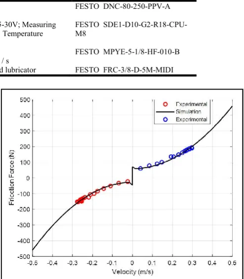
2 (4)where A1i and A2i are the transversal section areas in the chambers of the pneumatic cylinder i , and pai and pbi are the respective pressures in these chambers, whose values can be measured by means of pressure transducers. The study of pneumatic position servo systems is complex when compared with others position servo drives types, because air is very compressible and the friction force Fatri has a highly non-linear behaviour. Friction is a multifaceted non-linear phenomenon that exhibits many non-linear characteristics. They are composed by well-known and classic static friction (stiction), Coulumb friction, viscous friction and drag friction, that compose the simpler models based in static maps. Otherwise, they are composed by more complex dynamic phenomena known as Stribeck friction, rising static friction, frictional memory and presliding displacement (Valdiero, 2012). It is important to emphasize that, in general the friction characteristics are dependent of velocity, temperature, movement direction, lubrication and the wear between contact surfaces, and even position and movement history. It is possible to determinate easily the static parameters of the friction model through experimental tests carried out with constant velocity. These static parameters can be obtained through an experimental curve that represents a static map, plotting steady state velocity with corresponding friction force. This static map (Figure 8) was obtained through many experiments carried out with velocity values being changed from around null velocity to maximum system value. These experiments were fulfilled with test apparatus configured as an open loop system, when a constant pneumatic valve opening possibilities that pneumatic actuator moves with constant velocity. In this case, acceleration values zero and friction force is equivalent to the resulting force produce in actuator by pneumatic force, given by Equation (4) subtracted from the load force required to drive the robotic mechanism.
[image:5.595.92.504.78.169.2]The identification of steady state friction (Fatri,ss) is important because we can consider at constant speed that the result of the forces in the pneumatic actuator is:
Figure 8. Static friction-velocity map in steady state to pneumatic actuator with experimental values of the robot prototype for
rehabilitation
ss atri pi
Li
F
F
f
, ………(5)The Equation (5) is useful in force control with friction compensation of the pneumatically driven robotic workbench. As shown in Figure 4, the physiotherapist prescribes the desired movement trajectories for the exercise and the force limits that can be applied to the limbs. Then, from the signals of the angular displacement sensors and the force transducers mounted on the mechanism, the closed-loop control system performs the compensation calculations and sends the control signals to the pneumatic servo valves with the aim of maximizing the performance of the robot for rehabilitation.
Conclusions
This article deals with the application of pneumatic robots to assist in the physical rehabilitation of patients. The objective of this work is the design of a robotic rehabilitation workbench with low cost pneumatic drive. In the design of a pneumatically operated robotic machine, it is important to experimentally to identify the friction dynamics in pneumatic actuators, since they exhibit a non-linear behavior at low speeds, as shown in this article. As future work, the authors plan to build a prototype for testing and practical implementation.
Acknowledgments
[image:5.595.310.557.91.374.2]This study was financed in part by the Coordenação de Aperfeiçoamento de Pessoal de Nível Superior – Brasil (CAPES) – Finance Code 001. The authors also would like to thank CNPq (National Council for Scientific and
Table 1. Description of system component
Item Description Specifications Manufacturer/ Catalog Number 1 Differential Pneumatic Cylinder Diameter: 80 mm.
Course: 250 mm
FESTO DNC-80-250-PPV-A 2 Pressure Sensor Supply Voltage: 15-30V; Measuring
Range: 0 ... 10 bar; Temperature Range: 0 ... 50° C
FESTO SDE1-D10-G2-R18-CPU-M8
3 Proportional directional valve 5/3, closed center.
Rated flow: 0.7 m3 / s FESTO MPYE-5-1/8-HF-010-B
4 Air conservation unit Filter, regulator and lubricator FESTO FRC-3/8-D-5M-MIDI
Technological Development) and Finep (Funding Authority for Studies and Projects) by financial support at the Innovation Center for Automatic Machines and Servo Systems (NIMASS) in UNIJUÍ University. And Federal Institute Farroupilha.
REFERENCES
Barbosa, A. M, Carvalho, J. C. M. and Gonçalves, R. S. 2018. Cable-driven lower limb rehabilitation robot. Journal of the Brazilian Society of Mechanical Sciences and Engineering,
40:245.
Ben-Dov, D., and Salcudean, S. E. 1995. A force-controlled pneumatic actuator. IEEE Transactions on Robotics and
Automation, 11(6), 906-911.
Carvalho, J. C. M. and Gonçalves, R. S. 2010. Development of a Cable Driven Parallel Structure for Rehabilitation of Shoulder Movements. In: VI National Congress of Mechanical Enginering, Campina Grande, Brazil.
Díaz, I., Gil, J. J. and Sánchez, E. 2011. Lower-Limb Robotic Rehabilitation: Literature Review and Challenges, Journal of Robotics, Article ID 759764, 11 pages
Dubey, A. K., Mewara, H. S., Gulabani, K. and Trivedi, P. 2014. "Challenges in design &; deployment of assistive technology," International Conference on Signal
Propagation and Computer Technology (ICSPCT 2014),
Ajmer, pp. 466-469. doi: 10.1109/ICSPCT.2014.6884992 Gonçalves, R.S. and Carvalho, J. C. M. 2012. Robot Modeling
for Physical Rehabilitation. Service Robots and Robotics Design and Application. IGI Global, p. 154-175. DOI: 10.4018/978-1-4666-0291-5.ch009
Guo, S., Gao, J., Guo, J., Zhang, W., and Hu, Y. 2016. Design of the structural optimization for the upper limb rehabilitation robot. In Mechatronics and Automation (ICMA), 2016 IEEE International Conference on (pp. 1185-1190).
Hernandez, E., Valdez S. I., Carbone, G. and Ceccarelli, M., 2018. Design Optimization of a Cable-Driven Parallel Robot in Upper Arm Training-Rehabilitation Processes. In: Carvalho J., Martins D., Simoni R., Simas H. (eds) Multibody Mechatronic Systems. MuSMe Mechanisms and Machine Science, vol 54. Springer, Cham.
ISO 1219-1 2012. Fluid power systems and components - Graphical symbols and circuit diagrams - Part 1: Graphical symbols for conventional use and data-processing applications.
Kaitwanidvilai, S. and Parnichkum, M. 2005. “Force control in a pneumatic system using hybrid adaptive neurofuzzy model reference control” Mechatronics, vol. 15, no. 1, pp. 23–41. https://doi.org/10.1016/j.mechatronics.2004.07.003 Kweon, H. and Kim, Y. 2017. Tailor-Made Lower Limb
Rehabilitation Platform. In Computer Science and Intelligent Controls (ISCSIC), 2017 International
Symposium on (pp. 92-94). IEEE.
Lioulemes, A., Theofanidis, M., Kanal, V., Tsiakas, K., Abujelala, M., Collander, C., Townsend, W. B., Boisselle, A. and Makedon, F. 2017. MAGNI Dynamics: A Vision-Based Kinematic and Dynamic Upper-Limb Model for Intelligent Robotic Rehabilitation, International Journal of Biomedical and Biological Engineering, World Academy of Science, Engineering and Technology, Vol:11, No:4, pp. 158-167
Morales, R., Badesa, F. J., García-Aracil, N., Sabater, J. M., and Pérez-Vidal, C. 2011. Pneumatic robotic systems for upper limb rehabilitation. Medical & biological
engineering & computing, 49(10), 1145.
Nise N. S. 2007. Control Systems Engineering, John Wiley & Sons.
Pahl G. and Beitz W. 2013. Engineering design: a systematic approach. Springer Science & Business Media.
Plitea, N., Vaida, C., Carbone, G., Pisla, A., Ulinici, I. and Pisla, D., 2018. On the Kinematics of an Innovative Spherical Parallel Robot for Shoulder Rehabilitation. In: Carvalho J., Martins D., Simoni R., Simas H. (eds) Multibody Mechatronic Systems. MuSMe Mechanisms and
Machine Science, vol 54. Springer, Cham
Ponce, D., Mejia, L., Ponce, E., Martins, D., C.R.M. Roesler, and J.F. Golin, 2018. Kinetostatic Model of the Human Knee for Preoperative Planning: Part A. In: Carvalho J., Martins D., Simoni R., Simas H. (eds) Multibody Mechatronic Systems. MuSMe Mechanisms and Machine Science, vol 54. Springer, Cham
Rakova, E. and Weber, J. 2016. Exonomy Analysis for the Selection of the Most Cost-Effective Pneumatic Drive Solution. ASME. Fluid Power Systems Technology, 9th FPNI Ph.D,. Symposium on Fluid Power.
Valdiero A. C. 2012. Modelagem matemática de robôs hidráulicos. Ijuí: Unijuí.
Valdiero A. C. and Rasia L. A. 2016. Gestão de projetos de pesquisa e desenvolvimento de produtos mecatrônicos. In: Desafios em engenharia industrial. Ijuí: Unijuí, pp. 89–106. Valdiero A. C., Ritter C.S., Rios C. and Rafikov M. 2011. NonLinear Mathematical Modeling in Pneumatic Servo Position Applications, Hindawi Publishing Corporation. Mathematical Problems in Engineering. pp. 1-16.
Wolbrecht, E. T., Reinkensmeyer, D. J., and Bobrow, J. E. 2010. Pneumatic control of robots for rehabilitation. The
International Journal of Robotics Research, 29(1), 23-38.
Wu, J., Gao, J., Song, R., Li, R., Li, Y. and Jiang, L. 2016. The design and control of a 3DOF lower limb rehabilitation robot, Mechatronics, Volume 33, Pages 13-22, https://doi.org/10.1016/j.mechatronics.2015.11.010. Xiang L., Yun-Hui L. and Haoyong Y. 2018. Iterative learning
impedance control for rehabilitation robots driven by series elastic actuators, Automatica, Volume 90, Pages 1-7, https://doi.org/10.1016/j.automatica.2017.12.031.