http://dx.doi.org/10.4236/ica.2014.53013
A Reference-Pulse Generator for Motion
Control System
Nguyen Hoang Giap1, Jin-Ho Shin2, Won-Ho Kim2
1Department of Intelligent System Engineering, Graduate School of Dong-eui University, Busan, Korea 2Department of Mechatronics Engineering, Dong-eui University, Busan, Korea
Email: [email protected], [email protected], [email protected]
Received 17 May 2014; revised 22 June 2014; accepted 5 July 2014
Copyright © 2014 by authors and Scientific Research Publishing Inc.
This work is licensed under the Creative Commons Attribution International License (CC BY). http://creativecommons.org/licenses/by/4.0/
Abstract
This paper introduces a reference-pulse interpolator motion control system, which can be applied for computer numerical control (CNC) machine tools. The interpolation is calculated in DSP and the independent pulse generator modules are performed in FPGA, which can generate precise reference velocity profile and eliminate the path error of reference pulse interpolation. The pro-posed methodology has many advantages over existing reference-pulse interpolator controller, such as: real-time, extensibility, high flexibility and high precision motion profile planning.
Keywords
Motion Control, Reference-Pulse Interpolator, CNC Machine
1. Introduction
planning, and the control loop is implemented in the FPGA. In [8], a System-on-a Programmable-Chip (SoPC) with an embedded processor is implemented in FPGA to carry out motion profile generation and position con-trol algorithm, while current vector concon-trol is performed in FPGA. This technology enables software and hard-ware co-design to be parallel processing, hence increases the system performance and flexibility [8]-[10]. How-ever, all of above combinations are just developed in closed-loop control types.
Open-loop motion controller type generates reference signals, which is generally used for CNC systems such as water-jet cutting, machine tools, laser-beam cutters and welders. The reference signals from the controller can be transmitted as a sequence of reference pulse or as binary word in a sampled-data system [11]. The interpola-tor and signal generainterpola-tors are normally implemented in PC-based system with assembly language in order to save memory data and improve computing speed [11] [12]. In this system, the digital differential analyzer (DDA) method [11] [13] or stairs approximation method [12] [14] is used in hardware interpolators. Although the pro-gram design of geometric path planning is simple in PC-based control, the restriction of interpolation execution time of PC-based system makes it difficult to expand multi-axis motion system. Moreover, the design of inter-polator and pulse generation based on one interrupt clock employed in these methods causes path error and cannot generate constant instantaneous velocity [12]. In [12], a simple motion control approach is proposed by using two separate interrupt interval times at each interpolation step to generate constant velocity along geome-tric path. Although the precision is improved, this method still has error of half basic length unit.
In this paper we propose a new structure to overcome those drawbacks. Firstly, DSP is used to employ com-plicated calculation of the geometric path planning and motion profile generation. The order of velocity profile can be expanded to reduce jerk and vibration residue. Secondly, the binary velocity data of individual axis ob-tained from DSP are sent simultaneously to FPGA through Universal Host Port Interface (UHPI) at each sam-pling clock. A Master-Slave Wisbone interface (MSWI)module is designed in FPGA to communicate with DSP and pulse generator module through a First-In-First-Out (FIFO) memory buffer controller. Pulse generator mod-ules with high speed clock designed in FPGA receive the velocity data from DSP and generate output pulse in-dependently for each axis. The combination of interpolation calculation in DSP and independent pulse generator module in FPGA, along with the synchronous communication hardware structure, makes it possible to design a synchronous motion control system and eliminate the path error of reference pulse interpolation.
2. Design of Synchronous Motion Control System
2.1. Architecture of Synchronous Motion Control System
The reference pulse motion controller generates a sequence of pulses representing position and velocity to be controlled, which is usually based on an iterative technique controlled by an interrupt clock.
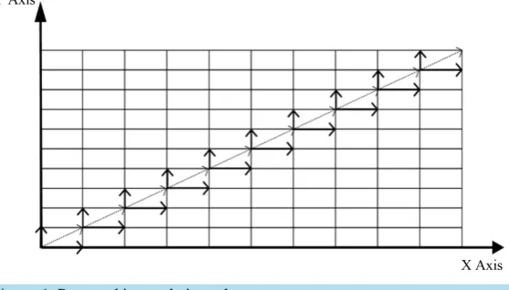
[image:2.595.162.441.554.713.2]In order to overcome the drawbacks of this kind of motion control, we proposed a new synchronous interpola-tion hardware and software structure, where the mointerpola-tion of each axis is independent with the system clock rate as shown in Figure 1. Consequently, the constant instantaneous velocity along the geometric path is generated and the error of pulse generator is eliminated.
The proposed controller is developed based on a high performance DSP and an FPGA. The geometric path planning and motion profile generation are calculated by DSP. At each interrupt clock, the interpolated velocity data of each coordinate are transferred to the pulse generator module through the MSWI. The MSWI module, designed in FPGA includes a Wishbone bus arbitration, a Wishbone master interface, a Wisbone slave interface for internal SRAM memory control, and Wishbone slave interfaces for connecting with the pulse generator module s through a FIFO buffer memory controller.
The FIFO buffer memory controller includes a timer and a shift register control. The signal i_clk and
r_clk_full represent the input clock and output for timer, respectively. The frequency of r_clk_full signal is equivalent to the clock interrupt of DSP. This timer ensures the velocity data to be transferred between DSP and pulse generator module of FPGA synchronously. Memory buffer contains velocity data r_data to gradually transfer to the pulse generator module at every sampling clock. Then these velocity data are accumulated in the pulse generator module to generate reference pulse. A shift register in the stack occurs when there exists veloci-ty input data i_wr_data from the host controller and i_time_trigger signal is active. The i_time_trigger signal indicates that the buffer memory is not empty and timer signal i_clk is active.
The bus arbitration in MSWI is used to inter-connect the bus control signals between master and slave module. This structure enables the interpolator velocity data to be transferred from DSP to pulse generator module s si-multaneously, and the corresponding pulse outputs generated for all coordinates are synchronous at each interval clock.
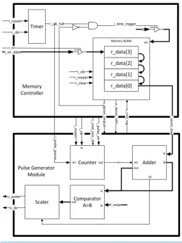
[image:3.595.165.432.357.713.2]Pulse generator module is connected with the Wishbone slave interface through a FIFO buffer memory con-troller as shown in Figure 2. This design protects the binary velocity data from the host concon-troller to be over-flowed. Consequently, the proposed controller is capable of generating synchronous and precise reference pulse signal for motion control system.
Figure 2. Pulse generator module.
2.2. Pulse Generator Module
Pulse generator module generates a sequence of signals o_pulse and o_dir representing reference position and moving direction of motion system, respectively. At each sampling time, the binary velocity data i_speed_data
are stored in memory buffer for pulse generation process.
Since the pulse signal is equivalent to one basic length unit (BLU), the pulse frequency is proportional to ve-locity, and the number of pulse is equivalent to the integration of velocity over time unit as in Equation (1):
0 d
t
P=
∫
BVU V t× (1)CLK
RANGE f BVU
f
= (2)
where P denotes the number of reference pulse output, BVU represents the basic velocity unit which is propor-tional to the frequency fclk of timer signal i_clk, and V is the reference velocity (pulse/sec), fRANGE is the
frequen-cy unit defines the input factor for Comparator block. Equation (1) can be rewritten in discrete type as:
0 N n RANGE nV P f =
=
∑
(3)CLK
n= f t (4)
where n is the output of Counter block.
The Counter and Adder block in pulse generator module acts as the velocity integrator. The integrator value
0 N n= nV
∑
is compared with fRANGE factor in the Comparator block. An output pulse o_pulse is toggle when0 2
N
RANGE n= nV ≥ f
∑
.3. Geometric Path Planning and Motion Profile Generation
Motion planning, including geometric path planning G(p) and motion profile generation p(t), plays an important role in machine control. With the rapid development of microprocessor technology, motion planning becomes flexible to employ [10]. In this section, we will discuss about the effective method to design a DSP-based mo-tion planning module that can be applied for reference pulse generator.
3.1. Motion Profile Generation
Motion profile is expressed as a parametric function of time p(t), which provides the corresponding desired po-sition and velocity at each instant. S-curve trajectory or seven-segment trajectory is used in motion control sys-tem to provide a smooth motion profile by adopting a continuous, linear piece-wise acceleration profile. In this manner, the resulting velocity is composed by linear segment connected by parabolic blends. Since the jerk is characterized by a step profile, the stress load by this motion profile is reduced.
The seven main parts of S-curve profile can be determined from the input coordinate motion data, as follows: 1st, 3rd, 5th, and 7th segments:
( )
2 30 0 0 max
1 1
2 6
p t = p +p t + p t + j t (5)
( )
20 0 max
1 2
p t = p +p t + j t (6)
2nd, and 6th segments:
( )
20 0 max
1
2
p t = p +p t + p t (7)
( )
0 max4th segments:
( )
0 maxp t =p +p t (9)
( )
maxp t = p (10)
where p t
( )
denotes the instant position, p0 is initial position, pmax is maximum velocity, and pmax ismaximum acceleration of geometric path, respectively.
3.2. Geometric Path Planning
Generally, geometric path planning including linear interpolation is common applied in industrial manufacture. Geometric path planning generates the reference position G p
( )
and velocity command G p( )
for individual coordinate which is used for reference pulse generator. The geometric path can be considered as a parametric vector function which represents the trajectory when the motion profile p t( )
moves over some interval of coordination as following:( )
X( )
Y( )
Z( )
G p = G p G p G p (11)
Linear interpolant is a straight line between two given points
(
GX0,GY0)
and(
GX1,GY1)
. For a value GXin the interval
(
GX0,GX1)
, the value GY along the straight line is calculated from the following equation:0 1 0
0 1 0
Y Y Y Y
X X X X
G G G G
G G G G
− −
=
− − (11)
The design of linear interpolation function in microprocessor is straightforward. The displacement of linear trajectory can be calculated as following:
(
) (
2)
21 0 1 0
l X X Y Y
p = G −G + G −G (12)
The interpolated position
(
GX,GY)
and velocity(
GX,GY)
of reference path can be presented as following:0 cos
X X l
G =G +p θ (13)
0 cos
X X l
G =G +p θ (14)
0 sin
Y Y l
G =G +p θ (15)
0 sin
Y Y l
G =G +p θ (16)
It can be seen from the above calculations, the instantaneous position and velocity data of individual axis can be implemented comprehensively in DSP by some calculations of motion profile generation and geometric path planning process.
4. Experimental Results
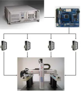
The overall motion control system shown in Figure 3consists of an embedded motion control board, a host PC to communicate with the board, 4 servo drivers to drive 4 AC motors of gantry mechanical system. In this expe-riment, only a vertical axis and a horizontal axis are used for linear move. The developed embedded motion control board, showed in Figure 4, includes a high performance DSP TMS320F2812 operating at 150 MHz and an FPGA XC3S1000 that has 1M system gates, 17,280 logic cells, and 391 I/O pins. The summary of the device utilization characteristic for the circuit of the FPGA is given in Table 1. The line driver 75ALS174A is used to convert the reference single-end pulse/dir signal from the FPGA to differential-end signal. The servo driver is set to operate in position mode. A quadrature encoder module (QEM) is designed in FPGA to observe the actual position of mechanical system. The line receiver is used to convert differential-end signal from rotary encoder of motor to single-end signal for QEM. The velocity profile data is send periodically from DSP to FPGA at the sampling clock frequency of 2 KHz. The pulse generator module in FPGA is able to generate pulse at maximum speed of 4 Mpps. The motion control board implemented in this paper can control system with up to 4 axes.
Figure 3. Multiple axis motion control system.
Figure 4. Developed motion control board.
Table 1.Device utilization summary.
Device Utilization Summary
Logic Utilization
Total Used %
Total Number Slice Registers 15,360 3594 23
Number of 4 input LUTs 15,360 5738 37
Number of occupied Slices 7680 3518 45
Total Number of 4 input LUTs 15,360 5975 38
Number of bonded IOBs 333 219 65
Number of BUFGMUXs 8 3 37
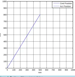
BLU of pulse generator module is 0.0001 mm. Figures 6-8, present the velocity profile, position profile and geometric path planning generated by linear interpolation. The actual position and velocity of each axis are ga-thered by QEM module from servo drivers to compare with the result of proposed reference pulse generators.
Figure 5.Reference pulse of X and Y axis along linear path using proposed controller.
Figure 6.Single axis velocity of linear interpolation.
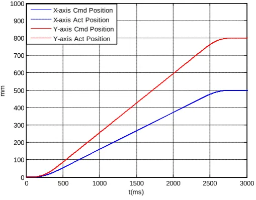
Figure 7.Single axis position of linear interpolation.
0 500 1000 1500 2000 2500 3000
0 50 100 150 200 250 300 350 400
t(ms)
mm/
s
X-axis Cmd Velocity X-axis Act Velocity Y-axis Cmd Velocity Y-axis Act Velocity
0 500 1000 1500 2000 2500 3000
0 100 200 300 400 500 600 700 800 900 1000
t(ms)
mm
[image:7.595.172.423.282.478.2] [image:7.595.171.426.507.706.2]Figure 8.Position of linear interpolation.
generated from two axes are uniform and synchronous. The velocity profiles in Figure 6and the position track-ing in Figure 7validate the calculation of motion profile generation in the DSP.
The experimental results prove the synchronous performance of developed controller applied in an industrial motion system. The flexibility and the open design of the motion board make it easy to develop and configure advanced motion control algorithm.
5. Conclusion
In this paper, we introduced a new synchronous reference pulse interpolator methodology for motion control system. The combination of proposed interpolation calculation in DSP and independent pulse generator module in FPGA can generate precise reference velocity profile and eliminate the path error of reference pulse interpo-lation. Therefore the proposed motion controller is applicable in high precision motion control system like CNC machine, planning machine, robot control.
Acknowledgements
This work was supported by Dong-Eui University Foundation Grant (grant number 2014AA492).
References
[1] Desborough, L. and Miller, R. (2002) Increasing Customer Value of Industrial Control Performance Monitoring— Honeywell Experience. In: Rawlings, J.B., Ogunnaike, B.A. and Eaton, J.W., Eds., 6th International Conference Chemical Process Control, AIChE Symp., Series 326, New York, AIChE.
[2] Volpe, R. (1993) Task Space Velocity Blending for Real-Time Trajectory Generation. Proceedings of IEEE Interna-tional Conference on Robotics and Automation, Atlanta, GA,2-6 May 1993, 680-687.
http://dx.doi.org/10.1109/ROBOT.1993.291880
[3] Macfarlane, S. and Croft, E.A. (2003) Jerk-Bounded Manipulator Trajectory Planning: Design for Real-Time Applica-tions. IEEE Transactions on Robotics and Automation, 19, 42-52. http://dx.doi.org/10.1109/TRA.2002.807548
[4] Meckl, P.H., Arestides, P.B. and Woods, M.C. (1998) Optimized S-Curve Motion Profiles for Minimum Residual Vi-bration. Proceedings of the 1998 American Control Conference, Philadelphia, PA, 21-26 June 1998, 2627-2631. [5] Kung, Y.-S., Tseng, K.-H. and Tai, T.-Y. (2006) FPGA-Based Servo Control IC for X-Y Table. Proceedings of IEEE
International Conference on Industrial Technology,Mumbai,15-17 December 2006, 2913-2918.
0 100 200 300 400 500 600 700 800 900 1000
0 100 200 300 400 500 600 700 800 900 1000
mm
mm
[6] Cho, J.U., Ngoc, Q.L. and Jeon, J.W. (2009) An FPGA-Based Multiple-Axis Motion Control Chip. IEEE Transactions on Industrial Electronics, 56, 856-870. http://dx.doi.org/10.1109/TIE.2008.2004671
[7] Shao, X., Shun, D. and Mills, J.K. (2006) A New Motion Control Hardware Architecture with FPGA-Based IC Design for Robotic Manipulators. Proceedings of IEEE International Conference on Robotics and Automation, Orlando, FL, 15-19 May 2006, 3520-3525.
[8] Xu, J., You, B. and Ma, L. (2008) Research and Development of DSP Based Servo Motion Controller. Proceedings of the 7th World Congress on Intelligent Control and Automation,Chongqing,25-27 June 2008, 7720-7725.
[9] Naouar, M.W., Monmasson, E., Naassani, A.A., Belkhodja, I.S. and Patin, N. (2007) FPGA-Based Current Controllers for AC Machine Drives—A Review. IEEE Transactions on Industrial Electronics, 54, 1907-1925.
http://dx.doi.org/10.1109/TIE.2007.898302
[10] You, B., Li, D. and Liu, S. (2007) Design of DSP-Based Open Control System for Industrial Robot. Proceedings of the IEEE International Conference on Automation and Logistics, Jinan, 18-21 August 2007, 1585-1590.
[11] Koren, Y. and Masory, O. (1981) Reference-Pulse Circular Interpolators For CNC Systems.Journal of Manufacturing Science and Engineering, 103, 131-136. http://dx.doi.org/10.1115/1.3184454
[12] Lho, T.J. and Kim, J.Y. (2000) A Study on Development of a PC-Based Software Interpolator for Two-Axis CNC Systems. TIT Research Journal, 3, 103-121.
[13] Koren, Y. (1976) Interpolator for a Computer Numerical Control System. IEEE Transactions on Computers, C-25, 32-37. http://dx.doi.org/10.1109/TC.1976.5009202
currently publishing more than 200 open access, online, peer-reviewed journals covering a wide range of academic disciplines. SCIRP serves the worldwide academic communities and contributes to the progress and application of science with its publication.