Error Identification and Correction for Memory
Application using Majority Logic Decoder and Detector
D.Subalakshmi
P G Scholar Department of EEE Kongu Engineering College
Major. P.S.Raghavendran,
Assistant Professor (Sr.G) Department of EEE Kongu Engineering College
ABSTRACT
Nano-memory is a new memory storage technology which may be used for memory applications such as aerospace, nano-bioengineering, etc. It provides smaller, faster and lower energy device. This technology blends together tiny carbon nano-tubes with conventional semiconductor. During encoding and decoding process, the error may occur in the codeword which results in the mismatching or loss of information. Error detection and correction are main issues in the memory which needs to be identified and corrected. The proposed method will identify the error and correct the error in the memory application using Majority Logic Decoder and Detector (MLDD). MLDD corrects the error based on number of parity check equation. This technology reduces the N-iteration to three N-iteration, if the codeword doesn’t contain any fault. It reduces the memory access time when there is no fault in data read. However it reduces the decoding time that increase memory application. This method uses decoder to detect the failure which minimizes the area and power consumption.
Keywords
Codeword, Iteration, MLD, MLDD.
1.
INTRODUCTION
In the present circumstances Complementary Metal-Oxide Semiconductor (CMOS) technology has rapidly proceeds to nano memory [2]. In memories, there may be mismatch of information or loss of information during encoding and decoding process. Since memories are one of the most commonly used type of circuits, it is important to protect them against error. Error Correcting Codes (ECCs) have been used for correcting the codeword in the memory. Static Random-Access Memory collapse rates are amplified extensively, as a result posing a main reliability concern for many applications [12].
Memories are most sensitive components to soft errors. Memory cells can be upset by less charge; there may be higher upset rate in past technologies [9]. Nano memory architectures used the memory central part and nano wire crossbars [3]. Error Correcting Codes are commonly used on memories. Codeword is parity bits and are appending with the data bits. Codeword is writteninto and read from the memories [6]. The Hamming codes and Hsiao codes are used to correct the single bit-flip and double bit-flips in the memory, area and performances are high [7] [11]. For multiple errors, codes needed more parity bits in the above methods and hence not efficient [1] [4] [5].
Bose-Chaudhuri-Hocquenghem (BCH)is authoritative random error correcting codes. It is used in the communication system. The demerits of these codes are redundancy requirement and complex decoding so they are not used in
high speed memory application [8]. Berlekamp-Massey, Euclidian and weight decoding algorithms require multi-cycles decoding, which is not adequate for embedded memories [10].Syndrome vectors are simple and power decoder. It detects the error in the codeword and corrects it. The drawback is that, for N-bits it will process N iteration. MLD is simple decoder and complexity. The demerits of the MLD are that performances of the system are reduced because it takes N-iteration for N-bit codeword [8].
This paper is organized as follows Section II discusses the overview of MLD method and syndrome vector. Section III presents the ML decoder and detector (MLDD). Section IV shows the results and discussion. Conclusion is made in Section V.
2.
MAJORITY LOGIC DECODER
Error control refers to mechanism to detect and correct the errors that occur in the codeword. The most common techniques for error control are as follows
• Error detection.
• Positive acknowledgement. • Retransmission after time-out. • Acknowledgement and retransmission.
MLD work is based on number of parity check equation. The ML decoder obtains the results after the iteration for the N-bit codeword. The codeword does not contain any error but it will take N-iteration. It will increase in the execution of the codeword process as well as power consumption. Figure 1 is the Schematic of MLD method. For this ML decoder, the codeword will be of 73 bit, it will process for 73-iteration and finally the output will be delivered. If the codeword does not contain any error, the ML decoder will process for 73 iteration and error in the codeword. The ML decoder iteration is useful for correcting the error in the codeword but mostly the error will not be in the jeopardy.
ML decoder is straightforward and capable of correcting the random errors in the codeword based on parity check equation. In this ML decoder, it consists of three modules. They are as follows
Fig. 1. Schematic of MLD method.
The input codeword bits are stored in the cyclic shift register and shifted to all the registers. It circulates all codeword bits of the register around both MSB and LSB ends with no loss of information. The schematic of the MLDD method is shown in Fig. 2. The cyclic shift register consists of two modules as follows:
• D flip-flop • Multiplexer
The in-between bits in each register are used to analyze the results from XOR matrix. In the Nth cycle, the results have attained the final register, and make the output bits. The codeword are corrupted by soft error which results in the wrong codeword. The codeword is passed to the shift register; the decoding process begins by calculating the parity check equation in the XOR matrix. The resulting values are forwarded to the majority gate module for calculating the correctness. If the number of 0’s is lesser than number of 1’s, that indicates the current bit of the codeword is wrong. To mitigate this problem, trigger signal is passed to correct the codeword. Otherwise there is no extra operation is needed which means the current bit is error-free.
The codeword in the register are rotated and the above process is taken place to check all the codeword. If there are N bits, the ML decoder process takes N iteration.
This algorithm needs N iteration for N bit codeword input. The main demerits are that performances of the MLD scheme based on the codeword size.
3.
SYNDROME VECTOR
Syndrome vector method overcomes the demerits of Majority Logic Decoder (MLD) method. The faulty codeword are decoder, by adding the fault detector which calculates the syndrome value. This will not affect the performances of the system because most of the codeword are error-free. The main drawback of this system increases the complexity to the design.
Based on parity check equation, the XOR matrix calculates the syndrome value. This increases the complexity of the syndrome value vector based on the size of the codeword. An error in the codeword is identified when the syndrome vector value is ‘1’, then the ML decoder is used to correct the wrong
4.
MAJORITY LOGIC DECODER AND
DETECTOR
The modified version of MLD that overcomes the disadvantages of Majority Logic Decoder and syndrome vector with Majority Logic Decoder method. MLDD is straightforward, power decoder and capable of correcting several random bit-flips that depending in the number of the parity check equation.
In the MLDD method, the 73-bit codeword input is encoded and decoded. If codeword does not contain any error, then the output will be processed in three iterations. Figure 2 shows the memory system schematic with MLDD. The advantages of this method are as follows
• High speed operation. • Low power consumption. • Execution time is reduced.
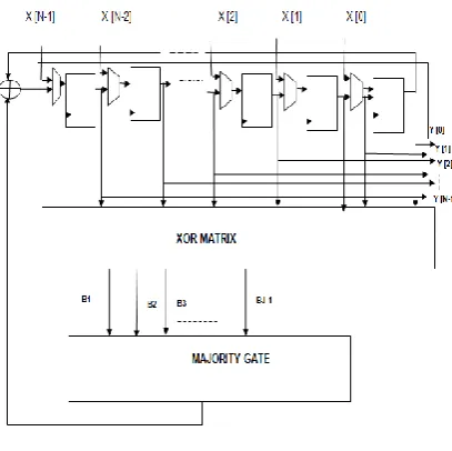
Fig. 2 Memory system schematic with MLDD.
In MLDD method, bit codeword is used. There will be 73-iteration, if there is error in codeword. Otherwise the output will be obtained after three iteration. Schematic of MLDD method shown in Figure 3 MLDD modules are as follows
• Cyclic shift register. • XOR-matrix. • Majority gate • Control unit.
[image:2.595.321.553.366.544.2]Fig. 3 Schematic of MLDD method.
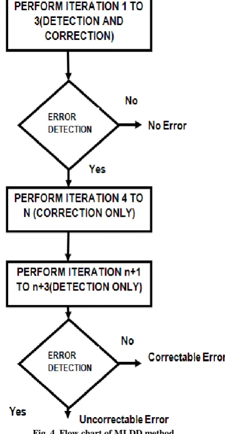
The algorithm for MLDD method is to detect the error and correct. The flow chart for MLDD method as shown in figure 4.
• Iteration from 1 to 3 will be performed for detection of the error in the codeword.
• If the codeword is error free then output will be obtained in three iteration. Otherwise iteration is continued to detect and correct the error in the codeword.
• Iteration from 4 to N will be preformed to correct the error in the codeword.
• Performances N+1 to N+3 iteration are to detect the error in codeword.
• If the error is detected then it will corrected. Otherwise retransmission will be processed
The cyclic shift register consists of two modules as follows
• D flip-flop
• Multiplexer
In the MLDD method, the cyclic shift register, shifts the 73-bit codeword depends on selection line input and XOR value [13]. The input codeword is given to cyclic shift register setting the selection line is zero, then the input codeword is progressed to output. If the selection line is one, the cyclic shift register shift the given input codeword based on the XOR value.
In the XOR-matrix, codeword are arranged based on set polynomial, such that all the bits are arranged in matrix form. Difference set is defined as a collection of integers chosen from the set such that no two of the ordered difference modulo are identical.The XOR-matrix output generated as one, and then the codeword has error. It helps to detect the error in the codeword. Majority gate produces the result based on the XOR-matrix. It depends on the maximum counted value and corresponding value. If the XOR-matrix maximum value is one, which means majority gate output will be one. This implies that the first bit codeword input does not contain error. But error may be presented in other bits.
Fig. 4. Flow chart of MLDD method.
Control unit is main module in MLDD method; it helps to produce the output in three iteration when there is no error in the memory system. Control unit triggers the tri-state buffer to produce the output in the three iteration. In the three iteration the OR gate assess the content from the recognized register. When the result is ‘0’ the Finite State Machine sent out the finish signal indicating that the processed codeword is error-free. In other case, if the output will be non-zero then iteration is continued and error is detected and corrected. Tri-state buffer initially stores the codeword. If the finish signal is passed to the tri-state buffer after three iteration, then output is displayed.
5.
RESULT AND DISCUSSION
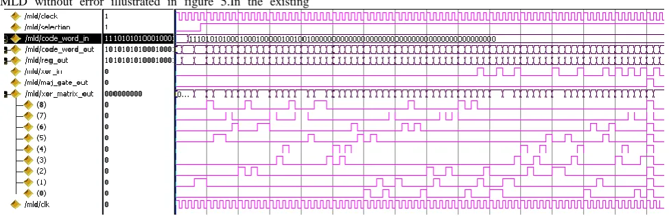
[image:3.595.56.289.84.282.2]is enabled, then right shifted as the value ‘0’ or ‘1’ depends on the XOR-matrix value. The XOR-matrix is used to detect the error in codeword. If there is no error in codeword then the
[image:4.595.63.525.70.175.2]output is depends on the matrix value. If the XOR-matrix value has maximum number of zero, then majority gate output will be zero. Otherwise output will be one.
Fig. 6 MLD method without error
MLD is used to detect and correct the error in the memory. In these existing methods the main drawback is iteration count is not reduced, when codeword does not contain error/fault. MLD without error illustrated in figure 5.In the existing
methods, syndrome vector and MLD method, the given codeword is without error, it will process till 73 iteration.MLD with error illustrated in figure 7.
Fig. 7 MLD method with error.
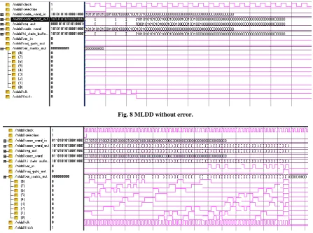
In this proposed MLDD method, the process of finding the error is same. The main aim is to reduce the iteration when codeword is faultless. The cyclic shift register, majority gate, XOR-matrix are identical as in MLD and syndrome. The various modules are Control unit, FSM, Counter, Tri-state buffer.
[image:4.595.59.546.239.367.2] [image:4.595.54.542.413.571.2]Fig. 8 MLDD without error.
Fig 9 MLDD with error.
5.1
Performances
The performances of the both MLD and MLDD method are illustrated. The number of data bits and parity bits are shown in table I.
T
ABLEI:
D
IFFERENCES
ETC
YCLICC
ODESN Data bit Parity bit
7 3 4
21 11 10
73 45 38
273 191 82
1057 813 244
To know the possible cases, all combination of bit flips is shown in Table II. The errors, detected in one iteration, has been improved which is illustrated in table III. In this method upto four bit error can be detected and corrected. The number of combination is shown in Table II. The codeword N=73 bits can be correcting upto four bit. Based on our design, the probability of finding the errors upto four bits in the first three iteration is less. Modifications may be done to improve the performances.
TABLE II: NO OF COMBINATION
M N No of combination
2
7 21
21 2100
73 2,630
5.2
Area
The performances of the proposed MLDD method is faster when compared to existing method MLD and MLD with syndrome vector.
The existing method MLD method needs less area compared to MLD with syndrome vector and MLDD method.
The performances of MLD with syndrome vector are high when compared to MLD method.
The proposed MLDD method, the speed is increased when compared to MLD and MLD with syndrome vector.
[image:5.595.311.544.454.529.2] [image:5.595.57.278.520.630.2]Iteration N Percentage
1 73 91.5
2 73 99.35
3 73 100
The whole decoding process is done to detect and correct the fault in the codeword. If it is assumed that the codeword has no error, the proposed method speed is increased in ideal condition. The results of two bit-flips are shown in Table III.
The area of the MLDD method is reduced with N bit codeword, when compared to MLD method. The MLDD method itself detects and corrects the error in the codeword. The MLDD method is not dependent on the size of the codeword.
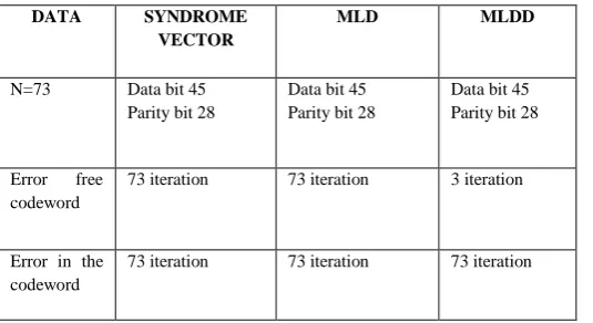
[image:6.595.50.285.225.320.2]The complexity of the MLDD method is less as compared to MLD with syndrome vector. The problem in MLDD method is that extra three iterations are required to shift the codeword. If the codeword is wrong, N iteration is required for the codeword to detect and correct the error. If codeword is error-free, the decoding process requires three iterations. The comparison of existing methods and proposed method are shown in table IV.
TABLE IV. Existing method and proposed method parameters.
DATA SYNDROME
VECTOR
MLD MLDD
N=73 Data bit 45 Parity bit 28
Data bit 45 Parity bit 28
Data bit 45 Parity bit 28
Error free codeword
73 iteration 73 iteration 3 iteration
Error in the codeword
73 iteration 73 iteration 73 iteration
In such case, silent fault corruption may occur. To reduce such fault, one more detection logic can be implemented after the completion of 73 iteration.
7.
REFERENCES
[1] K. Amir and B. Eric, “Fast, minimal decoding complexity, system level, binary systematic (41, 32) single-error-correcting codes for on-chip DRAM Application”, in Pro. IEE Int’tSymp. On Defect and fault Tolerance in VLSI System (DFT), San Francisco, Oct. 2001.pp 308-313.
[2] R.C. Baumann, “The impact of technology scaling on soft error rate performance and limit to the efficacy of error correction,” IEEE IEDM 2002, p. 329-332. [3] A. DeHon, S.C. Goldstein, P.J. Kuekes and P. Lincoln,
“Non-photolithographic nanoscale memory density prospects,” IEE Trans. Nano-technol., vol. 4, no.2, pp 215-228, Feb. 2005.
[4] W. Gao and S. Simmons, “A study on the VLSI implementation of ECC for embedded DRAM”, in Proc. Canadian Conf. on electrical and computer Engineering. Montreal, May 2003, vol. 3, no. 1, pp 203-206.
[5] S. Ghosh, S. Basu. And N.A. Touba, “Reducing power consumption in memory ECC checkers” , in Proc. Int’t Test Conf (ITC), Charlotte, Oct. 2004, pp. 1322-1331. [6] R.W. Hamming, “Error detecting and error correcting
codes”, Bell System Tech. J., vol. XXVI, no. 2, pp.147-160, April.
[7] M.Y. Hsiao, “A class of Optimal minimum Odd-weight-column SEC-DED Codes”, IBM Journal of R & D Vol. 14 July 1970, pp.395-401.
[8] S. Lin, D.J. Costello, “Error Control Coding: Fundamental and Application”, Prentice-Hall, 2004. [9] J. A. Maestro and P. Reviriego, “ Reliability of soft-error
correction protected memories”, IEEE Trans, on Reliability, vol. 58, no. 1, pp. 193-201, Mar. 2009. [10] D. Radaelli, H.Puchner, S. Wrong, S. Daniel,
“Investigation of multi-bit upsets in a 150nm technology SRAM device”, IEEE Trans. On Nucl. Sci. vol 52, Issue 6, pp. 2433-2437, Dec 2005.
[11] I.S. Reed, “ A class of multiple-error-correcting codes and decoding scheme,” IRE Trans. Inf. Theory, vol. IT-4, pp. 38-49.
[image:6.595.37.305.584.730.2]