41
Adaptive Resource Allocation in MIMO - OFDMA based on
Subcarrier Allocation (SA) and (GA)
K. Sumathi
Assistant Professor/ECE
Dr.Mahalingam College of Engineering and
Technology, Pollachi Tamil Nadu, India
M.L Valarmathi
Phd,Assistant Professor/CSEGovernment
College of TechnologyCoimbatore, Tamil Nadu,
India
ABSTRACT
In recent years, the eyes of scholars has been on the road to an proficient allocation scheme of signalling dimension between users in both uplink and downlink channels, since bandwidth is usually limited and/or very expensive. This paper covenants with the rate adaptive MIMO-OFDMA (Multiple Input Multiple Output-Orthogonal Frequency Division Multiplexing) downlink resource allocation scheme. It has an objective of maximizing the total system capacity subject to constraints on total power, bit error rate and proportional fairness. The proposed algorithm determines the number of subcarriers for each user and then handing over the subcarrier to each user. Two optimization methods, one based on Subcarrier Allocation (SA) and the other, based on Genetic Algorithm (GA) are used for resource allocation. In the optimization technique based on SA, using SVD (Singular Value Decomposition), the MIMO fading channel of each subcarrier is transformed into an equivalent bank of parallel SISO (Single Input Single Output) subchannels, which leads to a better trade-off strategy among system capacity, computational complexity and proportional fairness. Paralleled to static allocation schemes, the new algorithm has significantly lower complexity and in simulation fruitages higher system capacity. Simulation results show that the subcarrier allocation based on GA can provide capacity improvement with the reduction in fairness.
General Terms
Wireless Communications, Resource allocation
Keywords
OFDM, MIMO-OFDMA, resource allocation, Subcarrier Allocation (SA), power allocation, fairness, Genetic Algorithm (GA).
1. INTRODUCTION
It is necessary to give attention to the resource allocation as the need for high speed communication increases. In wireless communication the available spectrum is very limited, but the users are more. There comes the effective way allocating the
resources namely subcarriers, and subchannels adaptively in a fair and efficient way.
OFDM is a bandwidth efficient technique for multicarrier modulation. High data rates are achieved using OFDM (Orthogonal Frequency Division Multiplexing). In OFDM the wideband channel is partitioned into several narrowband channels by means of IFFT. OFDM divides the available bandwidth into many subchannels that are orthogonal to each other. This principle avoids the interference between the subcarriers. By adding Cyclic Prefix (CP), Inter-symbol Interference (ISI) on the carriers is removed. This makes OFDM suited to wireless communications applications. Some of the applications of OFDM are DAB, DVB. It is an efficient approach to combat the adverse effects of multipath spread, and is the main interface solution to many wireless systems [17] OFDMA (Orthogonal Frequency Division Multiple Access) is an extension of OFDM. OFDMA allows multiple users to transmit simultaneously on different subcarriers per OFDM symbol. A joint bit, power and subcarrier allocation is probed in [14].
The advent of multiple-input multiple-output (MIMO) technology is used in providing high rate reliable wireless communications [21]. MIMO/OFDM systems are able to multiplex the users in both the space and frequency domains. Multiple antennas increase capacity, transmission range reliability and suppress interfering signals. Several studies [4, 8, 16, and 17] of MIMO/OFDM carried out in multi-user environments. MIMO wirelesstechnology can able to increase the system capacity of a given channel obeying Shannon's law. By increasing the number of receive and transmit antennas the throughput of the channel can be increased linearly with every pair of antennas added. Hence MIMO wireless technology is one of the most important wireless techniques for future communication.
42 User 1
User 2 :
User U
Subcarrier apportionment
Base station Transmitter
Feedback Channel State Information from all users
Subcarrier information
Subcarrier and Power/bit Apportionment
User U receiver
MIMO-OFDM Transmitter
Subcarrier and Power/bit Apportionme nt
MIMO-OFDM Receiver
Antenna Antenna 1
Wireless
medium
:
:
:
:
Here we have to allocate the subcarrier and power in fair manner. The power doling out and subcarrier doling out scheme is devised to ensure fairness among users. In the first optimization technique, a value by the name, Fairness Safeguarding Factor (FSF) is introduced in the last part of the proposed subcarrier doling out algorithm to altercate subcarriers among users to ensure fairness. In the second optimization technique, Genetic algorithm (GA) is used to do subcarrier and power doling out.
The rest of this paper is organized as follows. In section 2, the MIMO-OFDMA system model and the capacity optimization objective function are introduced. In section 3 resource doling out based on the two optimization techniques are discussed. Section 4 shows simulation results and conclusions are given in section 5.
2. SYSTEM MODEL
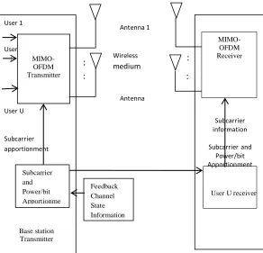
The block diagram of MIMO-OFDMA downlink system model is shown in the Figure 1. It is assumed that perfect channel state information is available at both the base station transmitter and receiver. At the base station, the resource doling out scheme is furthered to the MIMO-OFDM transmitter. This information is also sent via separate channel to the user. The user‟s data is transmitted via the MIMO channel from the base station and received by the user. The user decodes the data with the help of subcarrier doling out scheme received from the base station via a separate channel.
We assume a total of „U‟ users in the system sharing „S‟ subcarriers with total power Ptot and BER constraint. Our
objective is to maximize the total system capacity and care about fairness among users. Each user has „R‟ receiving antennas and the base station has „T‟ transmitting antennas. The channel gain of user „u‟ on subcarrier „s‟ is denoted as gu,s . The total
available bandwidth is B and total power is Ptot. Each subcarrier
„s‟ of user „u‟ is assigned a power pu,s. No is the noise power
spectral density. The corresponding signal-to-noise ratio (SNR)
is 2
,
/
u s o
B
g
N
S
and the uth
users received SNR is given
by γu,s =
2
, ,
u s u s
o
p
g
B
N
S
.To meet the BER constraints, the effective SNR has to be adjusted accordingly. The BER of a square M-level QAM with Gray-bit mapping as a function of received SNR γu,s and
number of bits ru,s canbe approximated to within 1dB for ru,s > 4
and BER < 10-3[18].
,
, ,
1.6
( ) 0.2 exp
2u s 1
u s
MQAM u s r
BER (1)
Solving for ru,s , we get
,
,
log
21
u s u s
[image:2.612.300.592.66.347.2]r
(2)Fig 1. MIMO-OFDMA downlink system model
where
ln(5
BER
) /1.6
, is known as SNR gap. The factor Γ which is the difference between the SNR needed to achieve a certain transmission data rate for a practical system and the theoretical limit is called the SNR gap. The total data rate for user „u‟ is,
u
u u s s
B
R
r
S
(3)It is assumed that the subcarriers cannot be shared among users. Each subcarrier has narrowband channel with „T‟ antennas at the base station and „R‟ antennas at the receiver, which can be modelled by an
R T
channel matrix H= [hij], where hij is thechannel gain at the receive antenna i from transmit antenna j. The SVD of H can be written as
0.5 *
H = UΛ V
(4) Where U and V are unitary matrices, V* denotes the transpose conjugate of V andΛ
is a diagonal matrix. The elements of1 2
([ ,
,...,
M])
diag
Λ
are real and M=minimum (T,R). Usually, the 1 value is higher than the other values. For this reason 1 is called as dominant Eigen mode channel. The SVD operation converts MIMO channel into independent SISO channels, where each channel carriers a portion of users data.
43
,
2 ( ) , , 2
1 1
1 1
, ,
1
1 2 1 2
1
max
log
subject to
1:
{1,2,..., }with { } being disjoint sets
C2:
with
0,
,
3:
:
:...:
:
:...
u s
u
u
i
U M u s u s
p u s i
o
U
U
u u u
u U
u s tot u s
u s
U
p g
B
S N
S
B
C
S
p
P
p
u s
C
R R
R
.:
U(5)
Ωu is the set of subcarriers assigned to user „u‟. The constraints
are denoted by C1–C3. The first constraint is on subcarrier allocation to ensure that each subchannel is assigned to only one user. The next constraint is on power doling out. C3 denotes the rate constraints of the system. The predetermined values
1
{ }
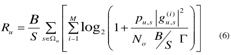
Uu are used to ensure proportionality among users.The capacity of user „u‟ is given by,
2 ( )
, ,
2 1
1
log
u
i M u s u s u
s i
o
p
g
R
B
S
N
S
B
(6)
The optimization problem given in (5) is NP-hard in nature, which means that an acceptable solution cannot be obtained with low complexity and in a short span of time. To solve this issue, two optimization techniques are proposed in the next section.
3. NEW SUBCARRIER DOLING OUT
SCHEME
Two optimization methods are explained here. First one is optimization based on SA followed by optimization based on GA.
3.1 Optimization Based On Subcarrier
Allocation (SA)
In this sliver, we discuss a suboptimal subcarrier doling out algorithm. The algorithm is suboptimal because equal power distribution in all subcarriers is assumed [19]. To reduce complexity, this scheme consists of two separate stages which are subcarrier doling out and power doling out as in [4, 16, and 17].
Step 1: Determine the number of subcarriers to be initially assigned to each user and unused subcarriers.
Step 2: Assign the subcarriers to each user as determined in the previous step. Then assign the unused subcarriers (if any) to the users with the aim of enhancing total system capacity.
Step 3: A Fairness Safeguarding factor (FSF) is used to reorganize subcarriers among users to ensure fairness.
Various notations used in the algorithm is explained below. cu,s is the subcarrier doling out indicator and cu,s=1, if subcarrier
„s‟ is assigned to user „u‟. Su denotes number of subcarriers
needed for user „u‟. Sunused is the number of unassigned
subcarriers. Rtot is the total data rate of all users.
In step 1, we determine the number of subcarriers for each user and initialize the variables. This initial step is based on the assumption that the proportion of subcarriers assigned to each user is approximately same as their eventual data rates and would roughly satisfy the proportionality constraints.
Step 2 consists of three substeps as explained below.
In step 2a, each user is assigned the subcarrier having maximum gain for that user. For each user, first subcarrier is allocated under the scheduling principle that the user with less pre-assigned Su has higher priority to choose his first subcarrier.
After doing this step, U subcarriers have been chosen. Thus there are (S-U) subcarriers available for users to select and user index should be reinitialized in the next step.
In step 2b, subcarriers are assigned to user according to the policy that the user with the least ratio of instantaneously achieved rate to its required proportion has the priority to choose one subcarrier at a time.
The user with most starvation to its desired proportion can feed him as much as possible through choosing additional subcarriers with better channel conditions. Since importance is given to proportional rates, the need of a user is determined by the user who has the least capacity divided by its proportionality constant. Once the user gets his allotment of Su subcarriers, he
can no longer be assigned any more subcarriers in this step. Proportional fairness among users is emphasized in this step.
In step 2c, remaining subcarriers Sunused are allocated to the best
users, wherein each user can get at most one unassigned subcarrier.
In step 3, we reorganize the subcarriers among user with most fairness and least capacity loss. For this reorganization purpose a factor called Deviation Indicator (DI) is introduced. This factor shows the overall deviation of all users from their desired proportions. When this value becomes smaller, the proportional fairness would be enhanced. DI=0 indicates ideal fairness.
The DI is given by
1 2 2
1
1
1
,
U
u u
u u U
u tot
u u
R
DI
U
R
(7)
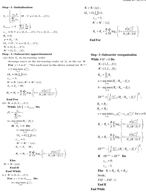
[image:3.612.55.287.321.377.2]A Fairness Safeguarding Factor (FSF) is used to control the number of subcarrier altercations. In each loop, subcarriers between two selected users with most unfair proportions are altercated. Thus this step is an iterative altercation process, which can enhance fairness at the cost of losing certain amount of capacity. The steps of the proposed algorithm are given in Fig 2.
To evaluate the fairness of the algorithm we define a parameter called Fairness Index (FI) as in [20].
44 2
1
2
1
U u u U
u u
FI
U
(8)
with the maximum value of 1 to be the fairest case in which all users would achieve the same data rate. Based on the above equation, a new parameter Fp is defined to examine the
performance of the algorithm in maintaining proportionality which is given by
2
1
2
1
/
/
U
u u u
p U
u u u
R
F
U
R
(9)
where Ruand αuare the achieved rate and the proportional rate
constraint for the uth user respectively. Fpis a real number in the
interval (0, 1] with the maximum value of 1 for the case that the achieved rate proportions among the users are the same as the predetermined set
{
u}
Uu 1.3.2 Optimization Based On Genetic
Algorithm (GA)
Genetic algorithm (GA) is a search heuristic that is derived from natural evolution. This heuristic is commonly used to generate useful solutions to optimization and search problems. Genetic algorithms belong to the larger class of evolutionary algorithms (EA), which generate solutions to optimization problems using techniques inspired by natural evolution, such as inheritance, mutation, selection, and crossover.
It is a method for solving both constrained and unconstrained optimization problems that is based on natural selection, the process that drives biological evolution and is based on the nature of survival of the fittest. Genetic Algorithms (GA) are not too hard to program or understand since they are biological based. Genetic algorithms are acknowledged as good solvers for tough problems.
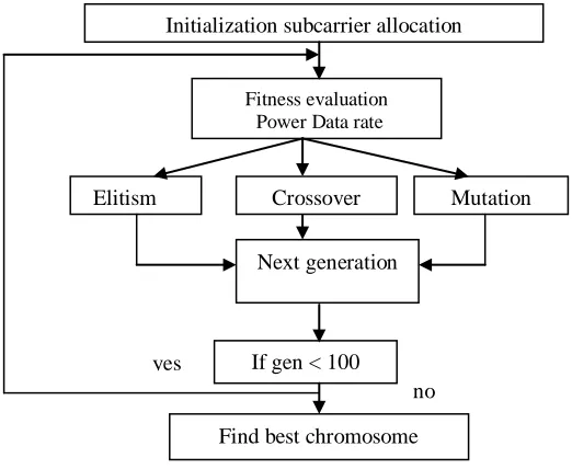
The steps involved in GA are given as flowchart in Fig 3. The algorithm starts with random set of solutions called population.
In each step (generation) new population is achieved from the old one. New individuals are created by crossing old ones (parents). Based on the fitness values the individual can become a parent.
The mutation is performed after cross over which produce children for next generation. The best solution in current generation is called elite. The population of 30 individuals is considered here for implementing this allocation.
Let an OFDM system have U (u = 1, 2. . . U) Users and S(s = 1, 2 . ., S) subcarriers. The system assigns a subset of N subcarriers to a user and determines the number of bits/symbol per each assigned subcarrier on downlink transmission.
1. Initialization: Generate a population Npopof chromosomes, where each bit of all the chromosomes is randomly picked from 1 to U.
2. Fitness evaluation: Update power allocation for each chromosome by using the subcarrier allocation presented by the chromosome and utilizing the corresponding power and subcarrier allocation of each chromosome, obtain the fitness value of each chromosome, which is the weighted capacity.
3. Elitism: Find Nelite chromosomes with the highest fitness values; copy them into the next generation directly.
4. Crossover: Pick two chromosome parents from the current generation to create chromosome children for the next generation. Randomly obtain a crossover point for the parents. Using those parents, single point crossover is done. Similarly, generate Ncrosscrossover children chromosomes for the next generation.
5. Mutation: Randomly pick a chromosome from the current generation, each bit of it can be changed with a chance of Pmu. Generate Nmu mutation children chromosomes for the next generation.
45
1
1 ,
, {1, 2,..., };
;
0, {1, 2,..., }, {1, 2,..., };
0;
/ ;
, {1, 2,..., };
{1, 2,..., }; {1, 2,..., u u U u u U u unused u u s u tot u S
S M u U
S
S S
M
c u U s S
R
p P S
u U
U S
Step - 1 : Initialization
K
N };
( )
1 / *for each user in the above sorted set * /
arg max
u
u
a Sort S in increasing order
Arrange users in the increasing order of S in the set
j to U
s
Step - 2 : Subcarrier apportionment
For K K (1) , , 2 ( ) , 2 1 ; { }; c 1; \ { }; \ { }; ;
log 1 ;
( / )
( ) {1, 2,..., };
> u s s N u u u s u u i M u s u u i o unused u g s u s
S S M
p g B
R R
S N B S
b U
S
End For
While Do
K K N N
K N 1 (1) , , ;
u= arg min( / );
S 0
s= arg max ;
{ }; c 1; { }; S u U u u u u u u u s s u u u s u u R g s s S M If Do
K NN N /
2 ( ) , 2 1 ( ) , ;
log 1 ;
( / )
\ { };
( ) {1, 2,..., };
1 to
u= arg max ;
i M u s u u i o unused i u s u p g B R R
S N B S
u
c U
s = S
g Else End If End While For Do K K K K , 2 ( ) , 2 1 \ { } ; { }; 1; { };
log 1 ;
( / ) u u k n i M u s u u i o u s c s p g B R R
S N B S
End For
K K
[image:5.612.48.528.53.685.2]N N /
Fig 2. Steps in the algorithm based on Subcarrier Altercation (SA)
1
0
={1,2,...,U};
={1,2....,S};
a
arg min(
/
);
arg max(
/
);
U
tot u
u
a tot a
a
b tot b
b
pre
FSF
R
R
R
R
b
R
R
DI
Step - 3 : Subcarrier reorganization
While
Do
K KK
N
1 2 2 1 1 2(1) (1) 2
, , , , 2 ( ) , 2 1 2 1
1
(
/
)
;
;
;
arg min(
) for
0;
log
1
;
( / )
log
1
U
u u tot u
t a
t b
b s b s a s a s s
i
M a e
a a i o M b b i
R
R
U
R
R
R
R
e
c g
c g
e
p g
B
R
R
S
N B S
p g
B
R
R
S
N 2 ( ) , 1 2 2 1 , , 1 2;
( / )
1
(
/
)
;
0;
1;
;
;
break;
i b e o post U
u u tot u
post pre
b e
a e
s t a t
N B S
DI
R
R
U
DI
DI
c
c
R
R
R
R
If
Do
Else
FSF
FSF 1;
46
2 3 4 5 6 7 8
0.5 0.6 0.7 0.8 0.9 1 1.1
Number of Users
F
a
ir
n
e
s
s
Fairness versus number of users
2 3 4 5 6 7 8
10.2 10.4 10.6 10.8 11 11.2 11.4 11.6 11.8
Number of users (U)
C
a
p
a
c
it
y
(
b
it
/s
/H
z
)
BW Efficiency vs Number of Users
FSF=0 FSF=5 FSF=10
[image:6.612.25.286.76.290.2]FSF=24 (MAX) GA TDMA
Fig 3. Steps in Genetic Algorithm (GA)
4. SIMULATION RESULTS
Here in the first part the simulation parameters required for doing the simulation is dealt followed by simulation snapshots and its descriptions
4.1 Simulation Parameters
[image:6.612.323.562.98.313.2]The simulation is done with the following parameters as shown in Table 1. Here we have taken the number of users as 8 and the subcarriers are 128 considering the bandwidth as 1 MHz.
Table 1. Simulation Parameters
PARAMETER VALUE
U 8
S 128
B 1 MHz
Ptot 1W
BER 10-3
Doppler shift 30 Hz
Maximum delay spread
5µs
No -80dBW/Hz
Channel model Frequency selective Rayleigh channel with six multipath
FSF 0,5,10,24
T=R 2
Proportionality
constants, α 1 with probability 0.52 with probability 0.3
4 with probability 0.2
p
Npop 30
Nelite 10
Ncross 14
Nmu 6
Pmu 0.01
Ngen 100
4.2 Simulation snapshots and descriptions
Fig 4. Capacity Vs Number of Users
Fig 5. Fairness Vs Number of Users
Next generation
If gen < 100
Initialization subcarrier allocation
Fitness evaluation Power Data rate
Crossover
Mutation
Elitism
yes
no
[image:6.612.332.562.386.611.2]47
Fig 6. Normalized rate Proportion Vs User Index
[image:7.612.43.290.383.600.2]Fig 6: Channel Gain Vs User index
Fig 7. Channel Gain Vs User index
Fig 4 shows the capacity to number of users. Here numbers of users taken are 8.This figure shows that there is an improvement in capacity when GA is used. There is reduction in capacity when the FSF factor gets increased. When FSF=0 the capacity starts from 10.8 bits/Hz and reaches a maximum value as 11.4 bits/Hz. For FSF = 5,10,24 it approximately starts from less than 10.8 bits/Hz and reaches a maximum value less than 11.4 bits/Hz. For TDMA it starts from 10.8 bits/Hz and reaches a maximum value nearer to 10.8 bits/Hz. Hence from the graph the performance of TDMA scheme is low when compared to SA and GA.
Fig 5 shows relation between fairness and the number of users. Here compared to the other methods GA provides increased capacity but at the cost of reduction in fairness among users. If fairness is not a main criterion then for capacity improvement GA can be used. GA provides poor fairness if the users starts increasing.
Fig 6 shows normalized rate proportion to user index. The normalized proportions for 8 users were taken. Here it was shown that the proposed scheme with maximum FSF value can attain close to optimal fairness. The maximum FSF value is chosen as 24 for the case of system with 8 users. The normalized
capacities are given by 16
1
/
u u k
R
R
. This is compared to the normalized proportionality constants. The rate is proportionally assigned to the users. When FSF=24, gives moderate performance. The performance of GA is also considered to be good over other methods.Fig 7 shows channel gain to user index.Channel characteristics for a system with two users and eight subchannels. The channel gains of user 1 have large variance while that of user 2 have smaller variance. It is due to multiuser diversity that a subchannel is rarely in deep fade for all the users. As a result of frequency selectivity of the channel, different subchannels of the same user experience different levels of fade. This figure represents the fact that the same subchannel may look deeply faded to one user while it may look good for the other.
For the GA based subcarrier allocation method, the parameters like the population size is Npop = 30, consisting of Nelite = 10 elites, Ncross = 14 crossover children and Nmu = 6 mutation Ngen = 100 were considered and the mutation probability Pmu is taken as 0:01.
5. CONCLUSIONS
In this paper two new resource doling out schemes with flexible controllability on capacity, fairness and complexity has been investigated. This paper gifts a new method to solve the rate adaptive resource doling out problem with proportional rate constraints for the MIMO-OFDMA systems. Under assumption that the perfect channel state information is available at both the transmitter and the receiver, the proposed algorithm presents an in effect scheme to conglomerate the advantages of MIMO, OFDM in the downlink. The proposed scheme based on SL with maximum FSF value achieves almost ideal fairness with a small capacity loss. This new scheme without subcarrier altercation may be used to capacity-emphasized scenario with acceptable reduced fairness. The scheme based on GA achieves higher capacity. But increased capacity with the reduction in fairness among users. So, when higher capacity is the only ultimate one could opt for optimization based on GA. Simulation results show that the proposed algorithms has better performance than the fixed subcarrier doling out scheme and can reduce computational complexity by using the dominant eigen channels (for SA). Using the wished-for schemes the system capacity is distributed more fairly among users. Therefore for different proportionality constraints, different rates can be achieved among users.
1 2
0 0.5 1 1.5 2 2.5 3 3.5 4 4.5
User index (u)
D
o
m
in
a
n
t
c
h
a
n
n
e
l
g
a
in
Snapshot of channel with two users and eight subchannels
1 2 3 4 5 6 7 8 0
0.05 0.1 0.15 0.2 0.25
User Index
N
o
r
m
a
li
z
e
d
r
a
te
p
r
o
p
o
r
ti
o
n
Normalized rate ratios per user with the desired proportions
48
6. REFERENCES
[1] Andrea Goldsmith, Wireless Communication, Cambridge University press 2005
[2] G.Bauch and A. Naguib, “Map equalization of space-time coded signals over frequency selective channels”, Proc. IEEE Wireless Communications. Network Conf., pp.261-265, September, 1999.
[3] Bin Da, C. C. Ko, “A New Scheme with Controllable Capacity and Fairness for OFDMA Downlink Resource Allocation”. in Proc. IEEE VTC 2007-fall, pp. 1817-1821.
[4] J. M. Choi, J.S. Kwak, H. S. Kim,and J. H. Lee, “Adaptive Subcarrier Bit, and Power Allocation Algorithm for MIMO-OFDMA System”, in Proc. VTC 2004-Spring, vol.3, pp.1801–1805.
[5] David Tse, Pramod Viswanath, “Fundamentals of Wireless Communication”, Cambridge University press 2006. [6] C. Fragouli, N. A;-Dhahir, and S. Diggavi, “Pre-filtered
space-time M-BCJR equalizer for frequency selective channels”,IEEE Trans. Commun., pp. 742-53, May 2002. [7] J. Hui, and Y. Zhou, “Enhanced Rate Adaptive Resource
Allocation Scheme in Downlink OFDMA System”, in Proc. IEEE VTC2006-Spring, vol. 5, pp. 2464-2468. [8] M. Kobayashi, G. Caire, “Iterative Water filling for
Weighted Rate Sum Maximization in MIMO OFDM Broadcast Channels”, in Proc. ICASSP Conf., vol. 3, April 2007, pp. 5-8.
[9] G. Li, and H. Liu, “On the Optimality of DownlinkOFDMA MIMO Systems”, in Proc. Signals, Systems and Computers Conf., vol. 1, November 2004, pp. 324-328.
[10]Naugib, “Equalization of transmitter diversity space-time coded signals,”, Proc. IEEE Globecom Conf., December 2000, pp.1077-82.
[11]M.S. Maw, and I. Sasase, “Resource Allocation Scheme in MIMO -OFDMA System for users Different Data Throughput Requirements”, in Proc. IEEE WCNC, March 2007, pp. 1706-1710.
[12]W. Rhee, and J. M. Cioffi, “Increase in Capacity of Multiuser OFDM System Using Dynamic Subchannel
Allocation”, in Proc. IEEE VTC, Japan, May 2000, pp. 1085-1089.
[13]Z. Shen, J. G. Andrews, and B. L. Evans, “Adaptive Resource Allocation in Multiuser OFDM Systems with Proportional Rate Constraints”, IEEE Trans. wireless communication, vol. 4, pp. 2726 - 2737, November 2005. [14]C. Y. Wong, R. S. Cheng, K. B. Letaief, and R. D. Murch,
„Multiuser OFDM with Adaptive Subcarrier, Bit, and Power Allocation‟, IEEE J. Select. Areas Communication, vol. 17, pp. 1747- 1758, October 1999.
[15]I. C. Wong, Zukang Shen, B. L. Evans, and J. G. Andrews, „A Low Complexity algorithm for Proportional Resource Allocation in OFDMA Systems‟, in Proc. Signal Processing Systems Conf., SIPS 2004, pp. 1-6.
[16]J. Xu, J. Kim, W. Paik, J. S. Seo, „Adaptive Resource Allocation Algorithm with Fairness for MIMO-OFDMA System‟, in Proc.VTC 2006-spring, vol. 4, pp. 1585-1589. [17]Y. J. Zhang, and K. B. Letaief, „An Efficient
Resource-Allocation Scheme for Spatial Multiuser Access in MIMO/OFDM Systems‟, IEEE Trans Commun., vol.53, pp.107-116, January 2005.
[18]S.T. Chung and A.Goldsmith, “Degrees of Freedom in Adaptive Modulation: A Unified View” IEEE Trans. Commun., vol 49, no.9, pp.1561- 1571, September 2001. [19]Bin Da and C.C. Ko, “Resource Allocation in Downlink
MIMO-OFDMA with Proportional Fairness”, Journal of Communications, vol.4, no.1, February 2009.
[20]Sanam Sadr , Alagan Anpalagan and Kaamran Raahemifar, “Suboptimal Rate Adaptive Resource Allocation for Downlink OFDMA Systems”, International Journal of Vehicular Technology, 2009.