ISSN(Online): 2319-8753 ISSN (Print): 2347-6710
International Journal of Innovative Research in Science,
Engineering and Technology
(An ISO 3297: 2007 Certified Organization)
Website: www.ijirset.com
Vol. 6, Issue 9, September 2017
Parallel Folded Architecture for Encoding and
Decoding the Polar (16,k) Code
Reddipogu Nissi Merlyn1, E.V Narayana 2
P.G. Student, Department of ECE, University College of Engineering, JNTUK, Kakinada, A.P,India1 Assistant Professor, Department of ECE, University College of Engineering, JNTUK, Kakinada, A.P,India2
ABSTRACT: The polar encoding is one among the most effective error correcting code attributable to the channel achieving property. It finds its application in communication, information theory. This property helps the polar codes to handle long length codes. Implementation of fully parallel encoder is easy when code length is small, as the code length increases the hardware implementation becomes more complex. Successive cancellation (SC) algorithm is viewed as a good candidate for hardware design of fully polar decoders due to its low complexity. To overcome this disadvantage the partially parallel encoder and decoder were designed. This newly designed encoder and decoder handles the long polar codes with less hardware complexity and can be used in the design of any polar code with any level of parallelism. The process is analyzed in the view point of very-large-scale integration.
KEYWORDS:Polar codes, partially parallel encoder and decoder, VHDL implementation.
I. INTRODUCTION
Polar codes were recently shown to be able to achieve the capacity of a wide class of communication channels while having very low encoding and decoding complexity [1]. Polar code is a linear block error correcting code. The code construction is based on a multiple recursive concatenation of a short kernel code which transforms the physical channel into virtual outer channels. As a result of the data rate achieving property, the polar code is presently thought of as a significant breakthrough to writing theory, and additionally the relevance of the polar code is being investigated in many applications, as well as information storage devices. Although the polar code has been thought about being with low Complexity, but it suffers from severe hardware complexity and long inactivity. Therefore, architecture that which will efficiently beware of long polar codes is necessary to make the VLSI implementation feasible.
Construction of polar codes encoding and decoding algorithms have been done [1]-[5]. Successive cancelation (SC), decoder has been traditionally used in [9]-[11]. On the other side, hardware architectures for polar coding have rarely been mentioned. Successive Cancelation (SC) decoding process, which isn’t appropriate for lengthy polar-codes owing to extreme hardware density. Linear block code with appropriate parameters can be used to perform block wise decoding of outer codes. Compared to the prior best channel codes, polar codes can potentially outperform LDPC codes in terms of error-correcting performance with the similar code-length and code rate. That means polar codes can help build more reliable and robust data transmission. As a result, they are viewed as the competitive channel codes candidate in the next generation of communication and storage systems.
II. RELATED WORK
ISSN(Online): 2319-8753 ISSN (Print): 2347-6710
International Journal of Innovative Research in Science,
Engineering and Technology
(An ISO 3297: 2007 Certified Organization)
Website: www.ijirset.com
Vol. 6, Issue 9, September 2017
proposed list decoder bridges the gap between successive-cancellation and maximum likelihood decoding of polar codes. Kai chen [5] presented improved versions of the cancellation (SC) decoding algorithm, successive-cancellation list (SCL) to improve the finite length performance of polar codes. G. Sarkis [6] [7] investigated the suitability of polar codes for data storage applications. The memory effects of the channel need be studied and a solution proposed that polar codes are suitable for data storage systems, and also presented an algorithm, architecture and FPGA implementation of a flexible, gigabit-per-second polar which increased the throughput of the decoder. B. Yuan [13] Presented reformulated SC list decoding algorithm. The latency is reduced without effecting performance by reformulated algorithm. K. K. Parhi [16] proposed a general approach to calculate the minimum number of registers in any digital signal processing (DSP) circuit for any arbitrarily specified life time chart and periodicity of computation. M. Ayinala [18] presented a novel approach can be used to derive partially parallel architectures of any arbitrary parallelism level. Using this approach parallel architectures have been proposed for computation of complex FFT base don radix-2 algorithms. The power consumption can be reduced by 37% and 50% in proposed 2- parallel and 4-parallel architectures respectively. These are very suitable for applications in implantable or portable devices due to their low area and power consumption.
III.POLAR ENCODING
The polar code belongs to the category of linear block codes, the encoding process can be characterized by the generator matrix. The generator matrix for code length N or is obtained by applying the nth kronecker power to the kernel matrix [1]. The generator matrix is given then the codeword is computed by x=u, where u represent information vector arranged in a natural order, and x represents codeword vector arranged in bit reversed order. The encoding complexity of 0(N log N) for a polar code of length N and take n stages when N=2n. For instance a polar code with a length of 16 bits is enforced with 32 XOR gates and processed with 4 stages within a total parallel encoder as shown in Fig.1. The fully parallel encoder is intuitively designed and supported on the generator matrix, however implementing such an encoder becomes a significant burden once an extended polar code is employed to achieve a good error correcting performance. The memory size and also range of XOR gates increase as the code length increases in implementations.
Fig.1 Fully parallel architecture for encoding a 16-bit polar code
ISSN(Online): 2319-8753 ISSN (Print): 2347-6710
International Journal of Innovative Research in Science,
Engineering and Technology
(An ISO 3297: 2007 Certified Organization)
Website: www.ijirset.com
Vol. 6, Issue 9, September 2017
IV.POLAR ENCODER AND DECODER
To design partially parallel encoder first the parallel encoding architecture is transformed to a folded form [15],[18], after that the lifetime analysis [16] and register allocation unit[17] are applied to the folded architecture. Lastly, the proposed parallel architecture for long polar codes is described.
FOLDING TRANSFORMATION
The folding transformation is widely used to save hardware resources by time multiplexing various operations on functional unit. A data low graph corresponding to the fully parallel encoding process is shown in Fig 2. Where node represents the kernel matrix operation F, wij and denotes the jth edge at the ith stage. Data flow graph (DFG) of the all parallel polar encoder is comparable to that of the Fast Fourier transform [18], [19] except that the polar encoder works on the kernel matrix in place of the butterfly operation. Given the 16 bit DFG, the 4-parallel folded architecture that processes 4 bits at a time can be accomplished with two functional units in each stage. Thus the functional unit computes 2 bits at a time. In the folding transformation finding folding sets, that represents the order of operations to be executed in a functional unit, is the most crucial design factor [15]. To construct folding sets, all operations in the fully parallel encoding are initially classified as separate folding sets. Since the input is in natural order, it is reasonable to alternatively distribute the operations in the consecutive order. Hence each stage consists of two folding sets, each of that entirely odd or even operation to be performed by a separate unit.
Fig.2 Data flow graph of 16-bit polar encoding
Considering the four parallel input sequence in a natural order, stage 1 has two folding sets of {A0, A2, A4, A6} and {A1, A3, A5, A7}. Each folding set contains four elements, and the position of an element represents the operational order in the corresponding functional unit. Two functional units for stage 1 execute A0 and A1 simultaneously at the beginning, and A2 and A3 at the next cycle, and so forth. The folding sets of stage 2 have the same order as those of stage 1, that is {B0, B2, B4, B6} and {B1, B3, B5, B7}, since the four parallel input sequence of stage 2 is equal to that of stage 1.
ISSN(Online): 2319-8753 ISSN (Print): 2347-6710
International Journal of Innovative Research in Science,
Engineering and Technology
(An ISO 3297: 2007 Certified Organization)
Website: www.ijirset.com
Vol. 6, Issue 9, September 2017
Cyclic shifting the folding sets right by one can be done by inserting one unit delay time, it gives the full utilization of the functional units by overlapping next iterations .As a result, folding sets{C6,C0,C2,C4}and {C7,C1,C3,C5}, of stage 3 are determined, where C6 is overlapped with A0 and B0 in the next iteration. Likewise, the functional unit processes a pair of inputs whose indices differ by 8 in stage 4. The folding sets of stage 4 are {D2, D4, D6, D0} and {D3, D5, D7, D1}.These are obtained by cyclic shifting the previous stage 3 folding sets by two. Generally speaking, a stage whose index s is less than or equal to log2 P, where P is the level of parallelism, has the same folding sets determined by evenly interleaving the operations in the consecutive order, and another stage whose index s is larger than log2 P has the folding sets obtained by cyclic shifting the previous folding sets of stage s −1 right by s −log2 P.
Consider the case with accurate delay when an edge wij from functional unit T to functional unit S has a delay of d, the delay requirements for wij in the F-folded architecture can be calculated more precisely as
D(wij) = Fd + t − s (1)
Where t and s denote the position in the folding set corresponding to T and S, respectively. Equation (1) is a simplified delay equation [15] derived by assuming that the kernel functional unit is not pipelined. For the 4-folded architecture, the delay requirements, i.e., D(wij) for 1≤ i≤ 3 and 0≤ j≤ 15 are review in Fig. 3. For example, w2,0 from
B0 to C0 requires one delay so d = 0, t = 1, and s = 0. Some edges indicated by circles have negative delays. For the folded architecture to be practical, the delay must be equal or larger than to zero for all the edges. Retiming or Pipelining techniques can be applied to the fully parallel DFG in order to ensure that its folded hardware has non negative delays. Negative delay of every edge should be adjusted by inserting at least one delay element to make the value of equation (1) non negative. We have to make sure that the two inputs of an operation pass through the same number of delay elements from the starting points If delay elements are different, additional delays are inserted to make the paths have the same delay elements.
In Fig. 3, for example, four edges with zero delays are specially marked with negative zeros so additional delays are required due to the mismatch of the number of delay elements. By inserting delay elements the DFG is pipelined, as shown in Fig. 2, where the dashed line indicates the pipeline cut set associated with 12 delay elements. For the pipelined DFG D’(wij) the delay requirements are recalculated based on equation (1) and shown at the below Fig. 3. As a result, 8 functional units and 48 delay elements are enough to implement the 4-folded 4-parallel encoding architecture based on the folding sets.
Fig: 3 Original delay requirements D(wij) and recalculated delay requirements D’(wij)
LIFETIME ANALYSIS AND REGISTER ALLOCATION:
ISSN(Online): 2319-8753 ISSN (Print): 2347-6710
International Journal of Innovative Research in Science,
Engineering and Technology
(An ISO 3297: 2007 Certified Organization)
Website: www.ijirset.com
Vol. 6, Issue 9, September 2017
clock cycles takes into account the next iteration and the current iterations are overlapped. Thus, the number of live variables is 12, by using this 12 delay elements the folded architecture can be implemented. After determination of the number of delay elements, each variable is allocated to a register.
Fig. 4. Linear lifetime chart for w2j and w3j.
For the above example, the register allocation is tabularized in Fig.5. In the register allocation table [17], first row shows the all registers and every row report how the registers are allocated at the corresponding cycle. According to 4-parallel processing, variables are carefully allocated to registers in a forward manner.
In Fig. 5, an arrow dictates that a variable stored in a register is migrated to another register, and the variable with circle indicates that it remains same cycle. For example, w2,0 and w2,4 are propagated to functional unit to execute operation C0 that produces w3,0 and w3,4. At the same time, and are propagated to another functional unit to execute operation C1 that gives w3,1 and w3,5. The moving of the other variables can be find by following the register allocation table (Fig5).
Fig. 5. Register allocation table for w2j and w3j
ISSN(Online): 2319-8753 ISSN (Print): 2347-6710
International Journal of Innovative Research in Science,
Engineering and Technology
(An ISO 3297: 2007 Certified Organization)
Website: www.ijirset.com
Vol. 6, Issue 9, September 2017
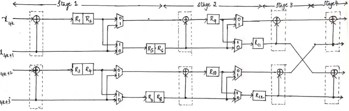
Fig. 6. 4-parallel folded architecture for encoding the polar (16, K) codes.
At first the SC algorithm was proposed. Different from other general approaches that can be applied to polar
codes, SC algorithm fully utilizes the structure of polar codes, and hence it is specifically suitable for decoding polar codes with low computation complexity. To date, SC algorithm has become the most popular decoding approach for polar codes. Since the date being introduced, polar codes have received significant attention from coding theory community. However, the adoption of new channel codes in IEEE standards does not only depend on the error-correcting performance, but also needs to consider the efficient VLSI design especially for decoders. To date, inefficient hardware performance of polar codes decoder has become the severe challenges that impede the practical use of polar codes, and these disadvantages on hardware are mainly caused by the inherent property of corresponding decoding algorithms. In general, polar codes can be decoded either with successive cancellation (SC) algorithm [5] or belief propagation (BP) algorithm [13]. They are inherent serial decoding approaches. Hence the corresponding hardware decoders have long latency that is intolerable for real-time transmission.
Fig. 7. Proposed 4-parallel folded architecture for decoding the polar (16, K) codes
ISSN(Online): 2319-8753 ISSN (Print): 2347-6710
International Journal of Innovative Research in Science,
Engineering and Technology
(An ISO 3297: 2007 Certified Organization)
Website: www.ijirset.com
Vol. 6, Issue 9, September 2017
V. SIMULATION RESULTS
Fig.8. Partially parallel Encoder Output
Fig. 9. Partially parallel Decoder output
VI. CONCLUSION
The encoder and decoder architecture is designed by using folding technique. The number of functional units required in the implementation of the proposed architecture, depends on the code length N and the level of parallelism
P. As the level of parallelism increases, the hardware complexity is significantly deteriorated and the complexity of register part is almost independent of the parallelism. This architecture saves the hardware by up to 73 %. Therefore partially parallel encoder and decoder architecture with parallelism of four is designed, which reduces the hardware complexity and delay.
REFERENCES
[1] E. Arikan, “Channel polarization: A method for constructing capacity achieving codes for symmetric binary- input memoryless channels,”
IEEE Trans. Inf. Theory, vol. 55, no. 7, pp. 3051–3073, Jul. 2009.
[2] R.Mori and T. Tanaka, “Performance of polar codes with the construction using density evolution,” IEEE Commun. Lett., vol. 13, no. 7, pp.519– 521, Jul. 2009.
ISSN(Online): 2319-8753 ISSN (Print): 2347-6710
International Journal of Innovative Research in Science,
Engineering and Technology
(An ISO 3297: 2007 Certified Organization)
Website: www.ijirset.com
Vol. 6, Issue 9, September 2017
no. 12, pp. 6253–6264, Dec. 2010.
[4] I. Tal and A. Vardy, “List decoding of polar codes,” in Proc. IEEE ISIT, 2011, pp. 1–5.
[5] K. Chen, K. Niu, and J. Lin, “Improved successive cancellation decoding of polar codes,” IEEE Trans. Commun., vol. 61, no. 8, pp. 3100–3107, Aug. 2013.
[6] G. Sarkis and W. J. Gross, “Polar codes for data storage applications,” in Proc. ICNC, 2013, pp. 840–844.
[7] G. Sarkis, P. Giard, A. Vardy, C. Thibeault, and W. J. Gross, “Fast polar decoders: Algorithm and implementation,” IEEE J. Sel. Areas Commun., vol. 32, no. 5, pp. 946–957, May 2014.
[8] G. Berhault, C. Leroux, C. Jego, and D. Dallet, “Partial sums generation architecture for successive cancellation decoding of polar codes,” in Proc.
IEEE Workshop SiPS, Oct. 2013, pp. 407–412.
[9] B. Yuan and K. K. Parhi, “Low-latency successive-cancellation polar decoder architectures using 2-bit decoding,” IEEE Trans. Circuits Syst.
I, Reg. Papers, vol. 61, no. 4, pp. 1241–1254, Apr. 2014.
[10] C. Leroux, A. J. Raymond, G. Sarkis, and W. J. Gross, “A semi-parallel successive-cancellation decoder for polar codes,” IEEE Trans. Signal Process., vol. 61, no. 2, pp. 289–299, Jan. 2013.
[11] A. J. Raymond and W. J. Gross, “Scalable successive-cancellation hardware decoder for polar codes,” in Proc. IEEE GlobalSIP, Dec. 2013, pp. 1282–1285.
[12] U. U. Fayyaz and J. R. Barry, “Low-complexity soft-output decoding of polar codes,” IEEE J. Sel. Areas Commun., vol. 32, no. 5, pp. 958–966, May 2014.
[13] B. Yuan and K. K. Parhi, “Low-latency successive-cancellation list decoders for polar codes with multibit decision,” IEEE Trans. Very Large
Scale Integr. (VLSI) Syst., DOI: 10.1109/TVLSI.2014.2359793, to be published.
[14] C. Zhang and K. K. Parhi, “Latency analysis and architecture design of simplified SC polar decoders,” IEEE Trans. Circuits Syst. II, Exp. Briefs, vol. 61, no. 2, pp. 115–119, Feb. 2014.
[15] K. K. Parhi, VLSI Digital Signal Processing Systems: Design and Implementation. Hoboken, NJ, USA: Wiley, 1999.
[16] K. K. Parhi, “Calculation of minimum number of registers in arbitrary life time chart,” IEEE Trans. Circuits Syst. II, Analog Digit. Signal Process., vol. 41, no. 6, pp. 434–436, Jun. 1995.
[17] C. Wang and K. K. Parhi, “High-level DSP synthesis using concurrent transformations, scheduling, allocation,” IEEE Trans. Comput.-Aided
Design Integr. Circuits Syst., vol. 14, no. 3, pp. 274–295, Mar. 1995.
[18] M. Ayinala, M. J. Brown, and K. K. Parhi, “Pipelined parallel FFT architectures via folding transformation,” IEEE Trans. Very Large Scale Integr.(VLSI) Syst., vol. 20, no. 6, pp. 1068–1081, Jun. 2012.