SOC based Self Healing Architecture for Data Security
S.Lakshmi Kantham
Research scholar, Dept of ECESathyabama Univerisity, Chennai - India.
S.Ravi,
PhD.Professor & Head, Dept of EE M.G.R.UNIVERSITY, Chennai-95, India
ABSTRACT
Protecting enterprises from hackers, viruses and other security vulnerabilities is a primary concern for all IT System. Since IT systems become more and more interconnected, they also become exposed to an increasing number of attacks. In order to develop high security systems, many have relied on intrusion detection and prevention systems (IDPSs) as a solution. In this paper, Host Based Distributed IDS with Multi Agent System (MAS) is proposed, where each node on the network will have an IDS agent runs independently and monitors network traffic, local activities, including user and systems activities, and communication activities. The IDS agents on each node in the network work together via a cooperative intrusion detection algorithm to decide when and how the network is being attacked.
Keywords
Distributed IDS, Agent, Multi Agent Systems, Routing, Intruder.
1.
INTRODUCTION
Anintrusion detection system(IDS) is a security management system for computers and networks. An IDS gathers and analyzes information from various areas within a computer or a network to identify possible security breaches, which include both intrusions from outside the organization and misuse attacks from within the organization [1]. IDS uses vulnerability assessment, which is a technology developed to assess the security of a computer system or network.
Existing IDS no longer be sufficient and efficient. Therefore we need to develop a new architecture and a technique to protect the network from the outside or inside intruders. The proposed Host Based Distributed IDSs with MAS can be used in conjunction with firewalls, which aim to regulate and control the flow of information into and out of a network[7]. IDPSs have become a necessary addition to the security infrastructure of nearly every organization [2], [14].
In this paper, a new Host Based Distributed IDS with Multi Agent System (MAS) approach is described, which provides security to resource management in the system [5],[16].
2.
Host-based -Distributed IDS with MAS
A multi-agent system (MAS) is a system composed of multiple interacting intelligent agents, each of which is an independent problem solving agent, come together to form some coherent whole on a host that identifies intrusions by analyzing network Traffics. Intelligent agents sense the dynamic network and acts on it, on behalf of its user, in order to meet its design objectives. The advantages of using intelligent agent systems are Distribution, Intelligence and
Scalability. Intelligent agents are capable of interacting with other agents in order to satisfy their design objectives[11]. Interaction among agents in MAS is mainly realized by means of communication. A more elaborate form of communication is by means of a blackboard structure. A blackboard is a shared resource, usually divided into several areas, according to different levels of abstraction in problem solving, in which agents may read or write the corresponding relevant information for their actions. Another form of communication is by message passing between agents, each agent must be able to deduce the intention of the sender regarding the sent message.
[image:1.595.312.551.395.563.2]3.
System Structure and Functionality
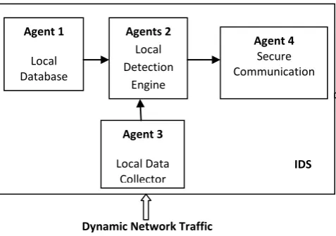
The proposed Host based IDS with MAS detect anomaly activities and it consists of various interactive intelligent agent[3],[4]. such as Local Database, Detection Engine, Data Collector and Secure Communication Module.Figure:1 Proposed Architecture for Distributed IDS with MAS
3.1.1
Local Database
The local database is the warehouses for the all information necessary for the IDS agent. The Local Database and Local Data collector Modules communicate directly with the Detection Engine to determine if any intruder is take place.
3.1.2
Local Data Collector
The Local Database module is responsible for gathering routing information by applying the optimization algorithm between the nodes. The cost of a link is configured by the network administrator. Cost factors may be the distance of a node. From current node a next hop router is derived for each destination. This forms the router's routing table. The route
Dynamic Network Traffic
Other IDS agent Agent 1
Local Database
Agents 2 Local Detection
Engine
Agent 3
Local Data Collector
Agent 4 Secure Communication
table is governed by link cost factors associated with each routing interface.
Let us consider the node be N = n1; n2, ….nn and the
targets T = t1, t2,…..tn . The cost of moving between
locations i and j is c(i; j) (i; j ε N U T). In our model c(i; j) is not pre-computed. The path cost of a given node, ni, is the
sum of costs from ni's initial location to all sequential targets
allocated to ni. For each node in network, we can run
[image:2.595.310.549.189.433.2]optimization algorithm from that node to destination to find the cost to all unallocated targets.
Figure 2 Weighted Networks
3.1.2.1
Optimization Algorithm for Detection of
Node Links based on Length
Let the Starting Source node S called as an initial node and the destination node D be the distance from the initial node. The Algorithm will assign some initial distance values and will try to improve them step by step.
1. Assign to every node a tentative distance value: set it to zero for the initial node and to infinity for all other nodes.
2. Mark all nodes unvisited. Set the initial node as current. Create a set of the unvisited nodes called the unvisited set consisting of all the nodes except the initial node. 3. For the current node, consider all of its unvisited
neighbors and calculate their tentative distances. If this distance is less than the previously recorded tentative distance, then overwrite that distance. Even though a neighbor has been examined, it is not marked as visited at this time, and it remains in the unvisited set. 4. Then, consider all of the neighbors of the current node,
mark the current node as visited and remove it from the unvisited set. A visited node will never be checked again; its distance recorded now is final and minimal. 5. If the destination node has been marked visited or if the
smallest tentative distance among the nodes in the unvisited set is infinity, then stop. The algorithm has finished.
6. Set the unvisited node marked with the smallest tentative distance as the next "current node" and
7. go back to step 3.
[image:2.595.46.260.213.364.2]3.1.2.2
Distance Matrix
Figure 2: Shows the Weighted network (N, c), with ‘c’ cost or lengths assigned to each edge and N is a set of elements
called nodes. The nodes of the graph are shown as points; edges are shown as lines connecting pairs of points. The length of a path in a weighted graph is the sum of the lengths of the edges on the path i.e. ∑ ci to j. An optimal path (or
shortest path) between a pair of ‘S’ (Source) and ‘D’ (Destination) in a weighted Network is a path from S to D with the least length. The least length between ‘S’ to ‘D’ is calculated by running optimization algorithm.
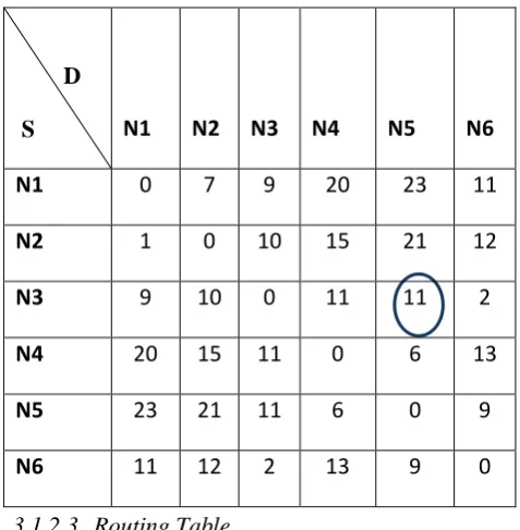
Table:1 Distance Matrix between the nodes
3.1.2.3
Routing Table
A routing table contains minimum the number of hops to each destination node. The hop count refers to the intermediate nodes through which the information flows between source and destination. In this work the Hop count is used to find out an intrusion in the network.
Table:2 Hop Count from S to D
D
S
N1
N2
N3
N4
N5
N6
N1
0
7
9
20
23
11
N2
1
0
10
15
21
12
N3
9
10
0
11
11
2
N4
20
15
11
0
6
13
N5
23
21
11
6
0
9
N6
11
12
2
13
9
0
D
S
N1
N2
N3
N4
N5
N6
N1
0
1
1
2
2
2
N2
1
0
1
1
3
2
N3
1
1
0
1
2
1
N4
2
1
1
0
1
2
N5
3
3/2
2
1
0
1
N6
2
2
1
2
1
0
11
7
9
6
15
1
0
2
14
9
1
6
5
3
2
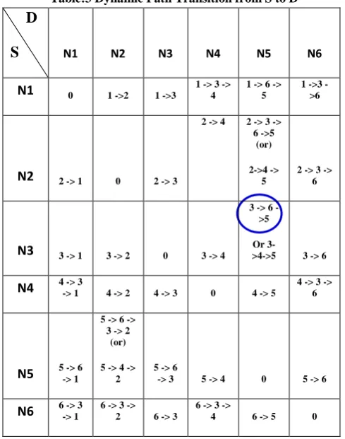
[image:2.595.316.548.537.744.2]3.1.2.4 Dynamic Path Transition
[image:3.595.43.288.165.476.2]Every node constructs amapof the connectivity to the network, in the form of a graph, showing which nodes are connected to which other nodes. Each node then independently calculates the next best logical path from it to every possible destination in the network. The collection of best paths will form the Dynamic Path Transition.
Table:3 Dynamic Path Transition from S to D
For example: consider the source ‘node 3’ and destination ‘node 5’ from tabulation 1,2,&3. The node 3 connected to node 5 by taking the least path. There is a two possible path from node 3 to node 5. They are 3 -> 6 -> 5 and other one is 3 -> 4 -> 5. The link cost is calculated by running optimization algorithm, for the first path the link cost is 11 and second path the link cost is 17. Therefore the network will take shortest path to reach destination node. Hence the network will select the first path i.e.,3->6-> 5 and number of hop count for this path is 2 (ref table:2).
A legitimate change in the routing table can be caused by the physical movements of nodes or network membership changes[12]. For a node, its own movement and the change in its own routing table are the only reliable information that it can trust. Hence, by using this data to detect the intrusion on the node(s) physical movements and the corresponding change in its routing table. The physical movement is measured mainly by distance. The routing table change is measured mainly by the positive or negative changed route i.e., changes in the sum of hops of all the routes, and the percentage of newly added routes[15].
3.1.3
Local Detection Engine
The local detection engine will use these data to detect local anomaly. The local anomaly is detected by low positive and high positive rate. The low positive rate calculates the percentage of normality variations detected as anomalies and High positive rate calculates as the percentage of anomalies detected.
Detection methods need broader data set collected from neighboring agents. This module check the local anomaly by verifying the routing information received from the local database and local database collector. If there is any mismatch in the routing table, then this module will alert to secure communication saying that there is an intrusion in the network otherwise it will allow to access system resources.
3.1.4
Secure Communication
The Secure Communication Module is necessary to enable IDS to communicate with other IDS on other nodes. It uses cooperative detective algorithms to detect intrusions in the network [9], [13].
4.
Intrusion Detection with help of Node
Search
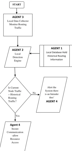
During first node search of the network, the individual node with their connectivity and their associated network traffic are recorded as historical routing information in the database of the Agent 1(Local Database) by executing optimization algorithm. Then, every subsequent node search the Agent 3 (Local Data Collector) captures the current network traffic and immediately sent this information to the Agent 2 (Local Detection Engine) to verify whether the current network traffic matches with the Historical routing information. If there is any mismatch in the node traffic then it will be considered as an intruder in the network and alerted to the system or other IDS nodes through the Agent 4 (Secure Communication).
4.1.1
Evaluation of Agent3
[image:3.595.315.543.583.743.2]During scanning of live hardware node by Agent 3, information can travel through any one of multiple hosts can have varying probability of transmission error. Also, varied proportion of messages can travel in each route. Figure 3 and Figure 4 shows the information flow in four independent servers in two routes[8],[10]. In Figure 3 the percentage of messages flowing in the two routes is indicated. Similarly, Figure 4 shows the servers that are selected corresponding to the two routes.
Figure:3 Probability of Error vs Route Flow
0 0.005 0.01 0.015 0.02 0.025
0 20 40 60 80
P
robabil
it
y
of
E
rr
or
Percentage
of MessageD
S
N1 N2 N3 N4 N5 N6N1 0 1 ->2 1 ->3
1 -> 3 -> 4
1 -> 6 -> 5
1 >3 ->6
N2 2 -> 1 0 2 -> 3
2 -> 4 2 -> 3 -> 6 ->5
(or)
2->4 -> 5
2 -> 3 -> 6
N3 3 -> 1 3 -> 2 0 3 -> 4
3 > 6 ->5
Or
3->4->5 3 -> 6
N4 4 -> 3 -> 1 4 -> 2 4 -> 3 0 4 -> 5
4 -> 3 -> 6
N5 5 -> 6 -> 1
5 -> 6 -> 3 -> 2
(or)
5 -> 4 -> 2
5 -> 6
-> 3 5 -> 4 0 5 -> 6
N6 6 -> 3 -> 1
6 -> 3 -> 2 6 -> 3
6 -> 3 ->
Figure:4 Server Vs % Message Flow
[image:4.595.53.290.304.490.2]In Figure 5 a sample study of the %nodes revealing the partitioned node address as the number of secured resources is accessed is shown.
Figure:5 Secured resources Vs the % nodes revealing their Partition Node address during use
4.1.2
Parameter
of
Live
Hardware
Node
Scanning
The different parameters of Live Hardware node(s) scanning are listed in Table 4. The parameters are used in the following manner:
Hardware node address: Host detection ‘D’.
Quality: To check the life time of a node i.e. energy aware routing applications
Range start to Range end: To form group communication and perform data broadcast activity.
Type Range/Subnet
Start Range Start Range End
Continuous Scan If enable continuously scan.
[image:4.595.323.571.341.693.2]Quality Value that represents quality of connection to the host in range.
Table: 4 Parameters of Live Hardware Node Scanning Systematic
The Input and Output Parameters of Live Hardware Node Scanning:
The inputs are, (i) Type, (ii) Range Start, (iii) Timeout, (iv) Concurrent Pings, (v) TTL, (vi) Pings per Scan Pass, (vii) Buffer Size, (viii) Continuous Scan, (ix) Nil Fragment The outputs are, (i) Signal Quality, (ii) HOST Address, (iii) Average Response time, (iv) Hostname
5.
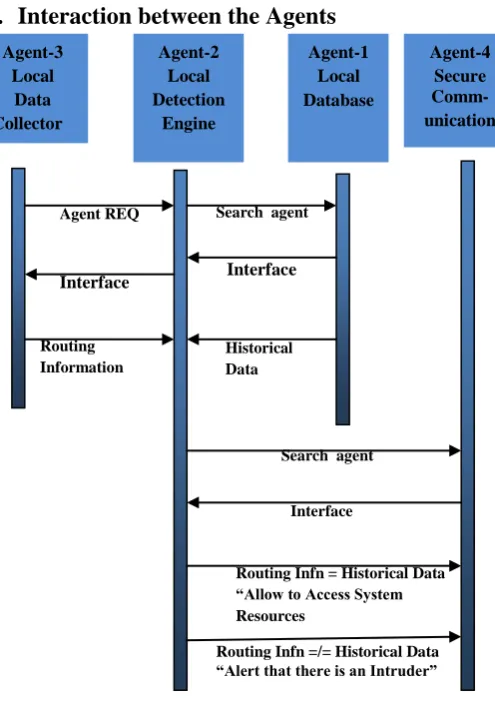
Interaction between the Agents
Figure:6 Interaction Diagram between the agents.
Figure 6 shows the Interaction of various agents involved in proposed model[6]. Each agent performs various tasks
0 10 20 30 40 50 60 70 80
1 2 3 4
Per
ce
n
tage
o
f M
e
ssag
e
s
Server
0 5 10 15 20 25 30 35 40 45 50
1 2 3 4
%
of N
od
es
No. of Secured Resources
% of Nodes reavealing IP Address
% of Nodes
Hardware Node Address
Hardware Node Address of the host.
Average Response Time
Average response time of the hardware in milliseconds.
Losses Ping request to which there was no response within required time.
Progress bar Scanner is running or not.
Log Items Current time, Hardware node names, Hardwar node Addresses and its status (Live or Dead).
Save Saving log items to the file.
Agent-4 Secure Comm-unication
Routing Infn =/= Historical Data “Alert that there is an Intruder” Routing Infn = Historical Data “Allow to Access System Resources
Interface
Search agent
Historical Data Interface Search agent Agent REQ
Interface
Routing Information Agent-3
Local Data Collector
Agent-2 Local Detection
Engine
[image:4.595.48.287.652.718.2]locally, and cooperates with each other to achieve a goal. The following sequences of operation are carried out:
Figure:7 Process Flow among agents.
6.
CONCLUSION
In this paper Host based – Distributed IDS with MAS is proposed. Agent 3 is tested with two routes and control over process of scanning is done through start, stop and wait method blocks thread. Also the class has events that notify user when state of scanning process is changed On Start Scan, On Stop Scan and On Restart Scan. Start method accepts hardware node address and calculating distance between the addresses. On Scan Progress Update event is raised each time
after the scanner finishes with and Hardware node Address which provides method of tracking progress to user. List of hardware node are available through Alive Hardware node property and when alive hardware node is discovered scanner raises On Alive Hardware node Found event to notify user. Each hardware node is represented by Hardware can hardware node State class.
7.
REFERENCES
[1] Moses Garuba, Intrusion Techniques: Comparative Study of Network Intrusion Detection Systems, 5th Internal Conference on Information Technology Pages 592-598 - 2008.
[2] Liwei Kuang and Mohammad Zulkernine, An Intrusion – Tolerant Mechanism for Intrusion Detection Systems. 3rd International Conference on Availability, Reliability and Security Pages 319-326, 2008.
[3] M.Rehak, M.echoucek and P.Celeda, Proc. Of 7th
International conference on Autonomous Agents and Multiagent systems (AAMAS-2008) – Industry and Applictions Track, Berger, Burg,Nishiyama(eds)., May 12-16, 2008, Estoril, Portugal,pp.133-136.
[4] Jin-Gang Cao, Gu-ping Zheng, Research on Distributed Instrusion Detection System Based on Mobile Agent, Proceeding of the 7th International Conference on Machine Learning and Cybernetics, Kunming, 12-15 July 2008.
[5] Jianxiao Liu, Lijuan Li, A Distributed Intrusion Detection System Based on Agents, 2008 IEEE Pacific-Asia Workshop on Computational Intelligence and Industrial Application.
[6] M.Syamala Devi and Manish Arora, Multi agent System for resource allocation and monitoring,African Journal of Mathematics and Computer Science Research Vol. 1(2), pp. 020-027, October, 2008
[7] Peng Liu and Jiwu Jing, Architecture for Self-Healing Database under Cyber Attacks, IJCSNS International Journal of Computer Science and Network Security, VOL 6 No.1B, January 2006.
[8] Min Sheng, Jiandong Li and Yan shi, “Critical Nodes Detection in Mobile Ad-hoc Network”, Proceeding of the 20th International Conference on Advanced Information Networking and Applications (AINA’06), IEEE Transaction 2006.
[9] G.Edward Suh, Jae W.Lee, Dravid Zhang, Srinivas Davadas, “Secure Program Execution via Dynamic Information Flow Tracking” ASPLOS’04, Boston, Massachusetts, USA, October 7-13, 2004.
[10] Hancock.D.L, Lamont.G.B “Multi-agent System for Network Attack Classification using Flow-Based Intrusion Detection: 2011 IEEE Transaction.
[11] Jia-Jun Xiong, Jing Zhang :A Kind of Multilayer Intrusion Detection System using Mobile Agent: 2003, IEEE Transaction.
[12] Chi-Ho Tsang, Kwong.S “Multi-agent Intrusion Detection System in Industrial Network using Ant Colony Clustering Approach and Unsupervised Feature Extraction” 2005 ICIT2005, IEEE Internation Conference on Computing & Processing, PP:51 - 56. No
Yes START
AGENT 3
Local Data CollectorMonitor Routing Traffic
AGENT 2
Local DetectionEngine
AGENT 1
Local Database HoldHistorical Routing Information
Is Current Node Traffic = Historical Routing Traffic?
Agent 4
Secure Communication-allow Resource
Access
Alert the System there is an Intruder
[13] Ye Du, Huigiang Wang, Yonggang Pang “Design and Implementation of Independent Agets – Based Distributed Intrusion Detection System” WCICA 2004, 5th IEEE conference on Intelligent Control and Automation, pp: 4343 - 4347
[14] Farhan.A.F, Zulkhairi.D, Hatim.M.T “Mobile Agent Intrusion Detection System for Mobile Ad Hoc Networks: A non-overlapping zone approach” ICI 2008, 4th IEEE/IFIP International Conference on Communication & Networking.
[15] F.A.Barika & N.E.Kadhi “Agent IDS based on Misuse Approach” Journal of Software Vol.4 No.6, August 2009.