An Intelligent Maximum Power Point Tracking Algorithm
for Wind Energy System
P.Devaki J.Devi Shree
S.Nandini
Associate Professor Assistant Professor PG Student
Dept.of Electrical Engineering Dept.of Electrical Engineering Dept.of Electrical Engineering Coimbatore Institute of Tech Coimbatore Institute of Tech Coimbatore Institute of Tech
Coimbatore, India Coimbatore, India Coimbatore, India
ABSTRACT
To obtain the maximum power from the variable speed wind generator, fuzzy logic controller is used. Hill-Climbing Search (HCS) technique is used to track the maximum power point. The maximum power is tracked for different wind speeds and load impedance variations. The measurement of wind speed, and rectifier output voltage are applied to fuzzy logic controller to estimate and control the optimal of maximum output power. The inputs to the FLC are the normalized values of error and variation of error. Triangular membership functions are used for input and output variables. The performance of both the schemes are simulated and a comparison is made. The simulation work is done in MATLAB 2010 environment.
Keywords
Maximum Power Point Tracking (MPPT), Permanent Magnet Synchronous Generator (PMSG), Fuzzy Logic Control (FLC), Variable-Speed Wind Turbine (VSWT), power converters.
1. INTRODUCTION
The diminishing reserves of fossil fuels, together with the associated environmental effects are encouraging more research in renewable clean energy. These renewable clean energy alternatives include solar energy, hydro energy and wind energy. The need to extract the maximum power available in the wind, research is taking place in numerous fields related to wind energy production. Intelligent control techniques are considered among the most important dimensions for the turbine efficiency and hence the control techniques enhancement has direct contribution to the better performance of wind turbines [1].
Variable-Speed Wind Turbines (VSWT) is advantageous mainly for their potential capability of extracting more energy from wind resources. To extract maximum energy from wind, a Maximum Power Point Tracking (MPPT) control is necessary to adjust the turbine rotor speed according to the variation of wind speed the Tip Speed- Ratio (TSR) is maintained at its optimal value [2]. Among previously developed wind turbine MPPT strategies, the TSR direction control method is limited by the difficulty in wind speed and turbine speed measurements [2][3]. Many MPPT strategies were then proposed to eliminate the measurements by making use of the wind turbine maximum power curve (or optimal torque curve), but the knowledge of the turbine’s characteristics is required. In comparison, the Hill Climbing
Searching (HCS) MPPT is popular due to its simplicity and independence of system characteristics [7]-[10].
2. MODELING OF THE SYSTEM
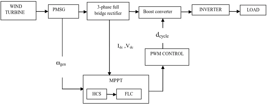
Figure 1 represents the wind energy conversion system used for the verification of the algorithm. A three-phase boost rectifier is used to simplify the control process and thus allows easy verification of the algorithm [6][8]. As for the generator, a Permanent Magnet Synchronous Generator (PMSG) is used due to its high efficiency, small size and no slip rings are necessary [3]. In Figure 1, ωgen is the generator angular speed; dcycle is the duty ratio, Vdc and Idc are the average voltage and current of the boost converter respectively. The MPPT control in this system is therefore obtained by changing the duty cycle of the switch of the boost converter. The use of the boost converter in Fig. 1 also allows Power Factor Correction (PFC) to be achieved at the output terminals of the PMSG.
For wind turbine, the static characteristic of the turbine (output as a function of wind speed) is described by the relationship between the total power and mechanical energy of the wind.
Pwind= ρπR 2
turbineν 3
wind (1)
Where ρ is the air density (1,225 kg/m3), Rturbine is the rotor radius (m), νwind is the wind speed (m/s),Cp is the power
coefficient, Pm is the mechanical power.
Pm= ρπR2turbineν3wind Cp (2)
If Ω is the rotor speed, the reduced speed λ is defined: λ = Ω (3)
The output torque of the turbine is calculated: Tm =
Ω (4)
The PMSG has been modeled in the rotor reference frame under the assumption of zero sequence quantities are not present and applying park’s transform, the terminal voltage of PMSG in the rotor reference frame is expressed as,
Vd =
Fig 1: Block diagram of Variable speed wind turbine generation system
Vq=
(6)
The expression of electromagnetic torque in the rotor is given by:
Te= p[(Ld-Lq)iqid-λmiq] (7)
where p is the number of pole pair, λm is the magnetic flux, Ld is the direct axis inductance, Lq is the inductance in quadrature, Rsis the stator resistance and ω is the electrical angular frequency[4].
Since the output of PMSG is AC,it is converted into DC for 3 phase full-bridge diode rectifier. The average value of Vdc is
Vdc=(3 VL)/π (8)
VL=line to line voltage of PMSG.
For boost converter, the relation between the input and output voltage and current are,
Vdc-out= Vdc-in (9)
D is the duty ratio of boost converter
Idc-out=(1-D)Idc-in (10)
D=1- (11) The peak to peak ripple of the output dc voltage ∆Vdc-out is ∆Vdc-out= (12)
C=capacitance of the boost converter. Fsb=switching frequency of boost converter.
For inverter, the PWM scheme may be evaluated under a certain switching frequency and reference signal frequency ratio, and the input and output voltage ratio. The definition of the modulation index ma is
ma=VLL/Vdc-out (13)
VLL=peak value of the line to line voltage.
The frequency modulation ratio mf is
mf =fs/f1. (14)
fs and f1 is the switching and modulation frequency.
The line to line rms voltage at the fundamental frequency is
VLL=
ma Vdc-out. (15)
3.
FUZZY LOGIC CONTROLLER
As shown in Figure 2, the FLC system consists of 3 components. They are fuzzification, the rule base, and defuzzification. Fuzzification, the first component of the FLC, converts the exact inputs to fuzzy values. These fuzzy values are sent to the rule-base unit and processed with fuzzy rules, and then these derived fuzzy values are sent to the defuzzification unit. In this unit, the fuzzy results are converted to exact values using centre of area method. In Figure 3 and 4, the error and the error variation of the input data of the FLC’s input variables areshown. Triangle membership functions were used. These functions are called NB, NM, S, PM, and PB, and the data vary between –1 and 1, as seen in the Figures [5]. The triangle membership function is defined as,
μMU(x) = max(min(
,
),0) (15)
[image:2.595.55.526.69.255.2]
Fig 2: Basic configuration of a FLC Defuzzification Rule base
Fuzzification
e
d e
d u PWM CONTROL
PMSG 3-phase full LOAD
bridge rectifier Boost converter INVERTER
gen
Idc ,Vdc
d
cycle WINDTURBINE
MPPT
In Figure 5, the output space of the FLC is shown. These data also vary between –1 and 1. In Table 1, the rules of the FLC are given. Due to the 5-ruled input variables, there are 25 rules in total.
Table 1. Fuzzy rule base
Fig 5: Output space
4. SIMULATION AND RESULTS
[image:3.595.52.234.119.721.2]
Fig 3: Error membership functions
Fig 4: Variation of error membership functions
[image:3.595.324.512.412.694.2]In Figure 6, the wind turbine is designed according to the wind characteristic equation. The wind turbine output power is given into the PMSG .In Figure 7, the FLC is designed with the help of fuzzification, fuzzy rule table and defuzzification model. It is designed to be 5-ruled. The minimum of the error and its variation to the input variables are calculated here. The centre of the area method is used in the defuzzification.
Fig 6: Simulation of wind turbine
e/de NB NM S PM PB
NB NB NB NM NM S
NM NB NM NM S PM
S NM NM S PM PM
PM NM S PM PM PB
PB S PM PM PB PB
NBe NMe Se PMe PBe
μ (e)
-1 -0.5 0 0.5
1
e
0 Sde
-0.5
NBde NMde PMde PBde
μ (de)
-1 0.5 1 de
Sdu
-0.5 0
NBdu NMdu PMdu PBdu
μ(du)
[image:3.595.61.226.503.716.2]Fig 7: Simulation of fuzzy logic controller.
[image:4.595.340.535.263.484.2]In order to verify control principle given in this paper, detail model of the system in MATLAB/Simulink has been developed. Figure 8 is the simulation waveform of stepwise wind speed. Figure 9 shows PWM signal and duty cycle variations are fed into the boost converter.
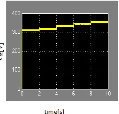
Fig 10: Boost converter voltage with fuzzy
Fig 8: Stepwise wind speed profile.
[image:4.595.77.272.346.602.2] [image:4.595.338.535.526.714.2]Figure 10 and Figure 11 shows boost converter voltage with and without FLC.On comparison it is observed, fuzzy logic controller is reduces the ripple and increases the voltage to certain level.
[image:5.595.63.273.221.438.2]Figure 12 shows, under variable wind speed condition voltage and current obtained are 420V, 4.7 amps at the inverter side for a constant load of 1000kW using fuzzy logic controller. Table 2 shows the inverter output for variable wind speeds for a constant load of 1000watts.
Fig 12: Voltage and current waveform for inverter
[image:5.595.318.538.336.538.2]
Fig 13: Rule surface of Fuzzy Logic Controller
Table 2. Output of inverter for variable wind speeds
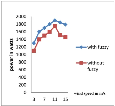
Graph 1 shows the comparison for maximum power of the system between with and without fuzzy logic controller under various wind speed condition.
Graph 1: Comparison between with and without fuzzy logic controller.
5. CONCULSION
A variable speed wind generator with fuzzy logic control is presented. The proposed fuzzy logic MPPT control was then combined with 3-phase boost converter. The system performance has been compared with fuzzy logic controller and without fuzzy logic controller. The system shows a fast convergence, accept noisy and inaccurate signals with fuzzy controller. The simulation result shows a stabilized maximum power should be obtained under variable wind speed and load variation with the introduction of fuzzy logic control.
0 200 400 600 800 1000 1200 1400 1600 1800 2000
3 7 11 15
p
o
we
r
in
w
att
s
wind speed in m/s
with fuzzy
without fuzzy Various
wind speed in m/s
Voltage in volts
Current in amps
Power in watts
11 420 4.7 1974
10 420 4.7 1974
9 420 4.7 1974
8 410 4.6 1886
7 410 4.6 1886
5 400 4.5 1800
4 400 4.5 1800
[image:5.595.62.271.502.720.2]6. REFERENCES
[1] Joanne Hui, Alireza Bakhshai, and Praveen K. Jain, Fellow, 2010 IEEE CONF, “A Master-Slave Fuzzy Logic Control Scheme for Maximum Power Point Tracking in Wind Energy Systems,” 978-1-4244-3384-1/10.
[2] Md. Arifujjaman, M. Tariq Iqbal, John E. Quaicoe, M. Jahangir Khan, May 2005,” Modeling And Control Of A Small Wind Turbine,” 2005 IEEE,CCECE/CCGEI, Saskatoon.
[3] Quincy Wang, and Liuchen,” SEPTEMBER 2004, An Intelligent Maximum Power Extraction Algorithm for Inverter-Based Variable Speed Wind Turbine Systems,” IEEE TRANSACTIONS ON POWER ELECTRONICS, VOL. 19, NO. 5.
[4] Eftichios Koutroulis and Kostas Kalaitzakis,” APRIL 2006, Design of a Maximum Power Tracking System for Wind-Energy-Conversion Applications,” IEEE TRANSACTIONS ON INDUSTRIAL ELECTRONICS, VOL. 53, NO. 2.
[5] Mostafa El Mokadem, Vincent Courtecuisse, Christophe Saudemont, Benoit Robyns and Jacques Deuse, FEBRUARY 2009,” Fuzzy Logic Supervisor-Based Primary Frequency Control Experiments of a Variable-Speed Wind Generator,” IEEE TRANSACTIONS ON POWER SYSTEMS, VOL. 24, NO. 1.
[6] Vladimir Lazarov, Daniel Roye, Dimitar Spirov and Zahari Zarkov, EPE-PEMC 2010,” Study of Control Strategies for Variable Speed Wind Turbine under Limited Power Conditions,” 14th International Power Electronics and Motion Control Conference.
[7] Ahmad Nadhir, Agus Naba, and Takashi Hiyama, August 2011,” Intelligent Gradient Detection on MPPT Control for VariableSpeed Wind Energy Conversion System,” ACEEE Int. J. on Electrical and Power Engineering, Vol. 02, No. 02.
[8] Evgenije Adzic, Zoran Ivanovic, Milan Adzic and Vladimir Katic , August 2011,”Maximum Power Search in Wind Turbine Based on Fuzzy Logic Control,” Acta Polytechnica Hungarica ,Vol. 6, No. 1.
[9] R. Datta and V.-T. Ranganathan, March 2003 ,“A method of tracking the peak power points for a variable speed wind energy conversion system,” IEEE Transactions on Energy Conversion, vol. 18, pp. 163– 168.
[10] M. Chinchilla, S. Arnaltes, and J.-C. Burgos, March 2006, “Control of permanent-magnet generators applied to variable-speed wind-energy systems connected to the grid,” IEEE Transactions on Energy Conversion, vol. 21, pp. 130–135.
[11] E. Koutroulis and K. Kalaitzakis, April 2006, “Design of a maximum power tracking system for wind-energy-conversion applications,” IEEE Transactions on Industrial Electronics, vol. 53.
7. AUTHOR PROFILE
Mrs.P.Devaki received her M.E degree in Electrical and Electronics Engineering with the specialization in Applied Electronics in 1999 from Bharathiar University, Tamil Nadu, India. .She is presently an Associate Professor in Electrical and Electronics engineering department. She is currently working toward the Ph.D. in Electrical Engineering. Her research interest includes renewable energy systems, power electronics and Power Systems.
Dr.J.Devi Shree received her Ph.D degree in Electrical Engineering from Anna University, Chennai, Tamil Nadu, India in 2008. She is presently Faulty in Electrical and Electronics Engineering Department. She has authored or coauthored more than 50 technical papers published in various journals and conferences proceedings. Her major area of research includes renewable energy systems and Power Systems.