Design of Fuzzy Logic Controller for Lateral Dynamics
Control of Aircraft by Considering the Cross-Coupling
Effect of Yaw and Roll on Each Other
Vishnu G Nair
Department of Aeronautical &
Automobile Engineering,
Manipal Institute of Technology
Manipal, India-576104
Dileep M V
Department of Instrumentation &
Control Engineering,
Manipal Institute of Technology
Manipal, India-576104
Prahalad K R
Department of Instrumentation &
Control Engineering,
Manipal Institute of Technology
Manipal, India-576104
ABSTRACT
In this paper, we explore fuzzy logic approach for lateral control of aircrafts. Here the effect of roll on yaw and that of yaw on roll is taken into account. The dynamic modeling of lateral control system that controls the lateral dynamics of an aircraft.is presented. The aircraft being considered in this work is a standard NAVION Transport aircraft [1]. A suitable mathematical model to describe the dynamics of an aircraft is derived. A single fuzzy controller is designed which will control both yaw and roll of the aircraft simultaneously. In this paper the transfer functions for yaw and roll is derived and their effects on each other is taken into account so that the system will have greater accuracy and efficiency than the application of two separate controllers. This design is very cost effective and will significantly reduce instability and increases maneuverability. Simulation results for the response of lateral controller are presented in time domain. Finally, the performance of lateral control system is analyzed based on common criteria of step’s response.
General Terms
Yaw,Roll, Cross-coupling,FuzzyLogic,Simulink
Keywords
Fuzzy logic controller, lateral dynamics, NAVION Transport aircraft, Matlab/Simulink
1 INTRODUCTION
The development of automatic control system has played an important role in the growth of civil and military aviation. The architecture of the flight control system, essential for all flight operations, has significantly changed throughout the years. Articulated surfaces were used at the beginning of aeronautical history for basic control. It was operated by the pilot through a system of cables and pulleys. This technique survived for decades and is now still used for small airplanes. The introduction of larger airplanes and the increase of flight envelopes made the muscular effort of the pilot, in many conditions, not sufficient to control the aerodynamic moments consequent to the surface deflection. This problem is solved by introducing aerodynamic balances and tabs, but further grow of the aircraft sizes and flight enveolpes brought to the need of powered systems to control the articulated aerodynamic surfaces. Modern aircraft include a variety of automatic control system that aids the flight crew in
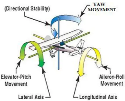
navigation, flight management and augmenting the stability characteristic of the airplane.The number and type of aerodynamic surfaces to be controlled changes with aircraft category. The control surfaces of an aircraft include the rudder, the elevator and the ailerons. The rudder is located at the rear of the vertical stabilizer. The rudder allows the plane to rotate on its vertical axis. The elevator is located at the rear of the horizontal stabilizer. The elevator allows the aircraft to rotate on its lateral axis. The ailerons are located at the rear of the main wing. The ailerons allow the plane to rotate on its longitudinal axis.When a plane is in flight we think of it being controlled on the three axes mentioned above. The longitudinal axis is the imaginary line running from the extreme nose to the extreme tail of the plane. The ailerons control the movement of the plane about this axis. Movement about this axis is called roll. The lateral axis runs from wingtip to wingtip at the center of gravity point. Movement on this axis is controlled by the elevator which causes the nose to move up or down. This movement is called pitch. The vertical axis runs through the top of the plane and out the bottom, intersecting the two axes. Rotation about this axis is controlled by the rudder which causes the nose to move left and right. This movement is called yaw.In this paper the designing of a lateral controller for controlling the yaw and roll simultaneously is explained. Fuzzy Logic Controller is used for controlling the yaw and roll of a standard aircraft ,by considering the cross coupling effect of both on each other is presented in this paper.
2 MATHEMATICAL MODELLING OF
THE SYSTEM
Figure 1.Yaw ,Roll& Pitch motion of Aircraft
[image:2.595.323.537.156.280.2]The forces, moments and velocity components in the body fixed frame of an aircraft system are shown in Fig. 2 where the aerodynamic moment components are represented by L, M and N;the angular rate components of roll, pitch and yaw axis are represented byp, q and r and the termsu, v and w represents the velocity components of roll, pitch and yawaxis.
Figure 2. Definition of forces, moments and velocity components in a body fixed frame [1].
For deriving the lateral equations we assumed that the aircraft is in steady cruise with constant altitude and velocity. Also it is assumed that change in pitch angle does not change the speed of aircraft and the reference flight conditions are symmetric with propulsive forces constant. Therefore,
𝑣 = 𝑝 = 𝑞 = 𝑟 = 𝜑 = 𝜓 = 0 (1)
𝑌 + 𝑚𝑔𝐶𝜃𝑆𝜃= 𝑚( 𝑑𝑣
𝑑𝑡+ 𝑟𝑢 − 𝑝𝑤) (2)
𝐿 = 𝐼𝑋 𝑑𝑝 𝑑𝑡− 𝐼𝑋𝑧
𝑑𝑟
𝑑𝑡+ 𝑞𝑟 𝐼𝑧− 𝐼𝑦 − 𝐼𝑋𝑧𝑝𝑞 (3)
𝑁 = −𝐼𝑋𝑍 𝑑𝑝 𝑑𝑡+ 𝐼𝑍
𝑑𝑟
𝑑𝑡+ 𝑝𝑞 𝐼𝑦− 𝐼𝑥 − 𝐼𝑋𝑧𝑞𝑟(4)
Using small-disturbance theory we can linearize the above equations by replacing all the variables in equations (2),(3) and(4) with a reference value plus a small disturbance. See equation (5)
𝑢 = 𝑢𝑜+ 𝛥𝑢 ;𝑣 = 𝑣𝑜+ 𝛥𝑣;𝑤 = 𝑤𝑜+ 𝛥𝑤
𝑝 = 𝑝𝑜+ 𝛥𝑝; 𝑞 = 𝑞𝑜+ 𝛥𝑞; 𝑌 = 𝑌𝑜+ 𝛥𝑌
𝑟 = 𝑟𝑜+ 𝛥𝑟; 𝐿 = 𝐿𝑜+ 𝛥𝐿; 𝑀 = 𝑀𝑜+ 𝛥𝑀
𝛿 = 𝛿0+ 𝛥𝛿 (5)
The equations (6),(7) and (8) represents the linearized form, see [1].
𝑑
𝑑𝑡− 𝑌𝑉 𝛥𝑣 − 𝑌𝑃𝛥𝑝 + 𝑢0− 𝑌𝑟 𝛥𝑟 − 𝑔𝑐𝑜𝑠𝜃0 𝛥𝜙 = 𝑌𝛿𝑟𝛥𝛿𝑟 (6)
−𝐿𝑉𝛥𝑣 +
𝑑
𝑑𝑡− 𝐿𝑃 𝛥𝑝 − 𝐼𝑋𝑍
𝐼𝑋
𝑑
𝑑𝑡+ 𝐿𝑟 𝛥𝑟
= 𝐿𝛿𝑎𝛥𝛿𝑎+ 𝐿𝛿𝑟𝛥𝛿𝑟 (7)
−𝑁𝑉𝛥𝑣 +
𝑑
𝑑𝑡− 𝑁𝑟 𝛥𝑟 − 𝐼𝑋𝑍
𝐼𝑍
𝑑
𝑑𝑡+ 𝑁𝑃 𝛥𝑝
= 𝑁𝛿𝑎𝛥𝛿𝑎+ 𝑁𝛿𝑟𝛥𝛿𝑟 (8)
The lateral directional equations of motion consist of the side force, rolling moment and yawing moment equations of motion. In this paper we are taking sideslip angle Δβ instead of the side velocity Δv. These two quantities are related to each other in the following way;[3]
𝛥𝛽 ≈ tan−1𝛥𝑣
𝑢0
=𝛥𝑣 𝑢0
(9)
Lateral equations of motion in state space form is shown in equation (10) 𝛥𝛽′ 𝛥𝑝′ 𝛥𝑟′ 𝛥𝜙′ = 𝑌𝛽 𝑢0 𝑌𝑃
𝑢0 −(1 −
𝑌𝑟
𝑢0)
𝑔𝑐𝑜𝑠 𝜃0
𝑢0
𝐿𝛽 𝐿𝑃 𝐿𝑟 0
𝑁𝛽 𝑁𝑃 𝑁𝑟 0
0 1 0 0 𝛥𝛽 𝛥𝑝 𝛥𝑟 𝛥𝜙
+
0 𝑌𝑈𝛿𝑎0
𝐿𝛿𝑎 𝐿𝛿𝑟
𝑁𝛿𝑎 𝑁𝛿𝑎
0 0 𝛥𝛿𝑎
𝛥𝛿𝑟
(10)
In this study, the data from NAVION Transport [1] is used in system analysis and modeling. Table I. gives the lateral directional derivatives stability parameters for this airplane The values are taken directly from reference [3], as these are standard data of the NAVION aircraft.
Table 1. The lateral directional derivatives stability parameters [3] General Aviation Airplane: NAVION Y-Force Derivatives Yawing Moment Derivatives Rolling Moment Derivatives Pitching Velocities
𝑌𝑉= 0.254 𝑁𝑣= 0.025 𝐿𝑣 = −0.091
Side Slip Angle
𝑌𝛽
= −44.665
𝑁𝛽= 4.549 𝐿𝛽= −15.969
Rolling Rate
𝑌𝑃= 0 𝑁𝑃
= −0.349
𝐿𝑃= −8.395
Yawing Rate
𝑌𝑟= 0 𝑁𝑟= −0.76 𝐿𝑟= 2.19
Rudder Deflection 𝑌𝛿𝑟 = 12.433 𝑁𝛿𝑟 = −4.613
𝐿𝛿𝑟= 23.09
Aileron Deflection
𝑌𝛿𝑎= 0 𝑁𝛿𝑎
= −0.224
𝐿𝛿𝑎
[image:2.595.63.293.358.527.2]The values in the above table is substituted in equation (10).
𝛥𝛽′ 𝛥𝑝′ 𝛥𝑟′ 𝛥𝜙′
=
−0.254 0 −1 0.183 −15.969 −8.395 2.19 0
4.549 −0.349 −0.76 0
0 1 0 0
𝛥𝛽 𝛥𝑝 𝛥𝑟 𝛥𝜙
+
0 0 23.09 23.09 −4.613 −0.224
0 0 𝛥𝛿𝑎
𝛥𝛿𝑟 (11)
Solving equation (11),the transfer functions for yaw and roll are derived. Transfer function for rudder deflection angle to yaw angle is given by equation (12)
𝛥𝜙 (𝑠) 𝛥𝛿𝑟(𝑠)
=
−4.6130 𝑆3−47.9562 𝑆2−11.8833 𝑆+5.7410
𝑆4+9.4090 𝑆3+14.0189 𝑆2+48.4991 𝑆+0.3979
(12)
Transfer function from aileron deflection angle to roll angle is given by equation (13)
𝛥𝜙 (𝑠) 𝛥𝛿𝑎(𝑠)
=
−32.32𝑆2−31.8𝑆−162 .08
𝑆4+8.402 𝑆3+13.3𝑆2+51.5 𝑆+0.569(13)
3 DESIGN PROCESS OF FUZZY LOGIC
CONTROLLER
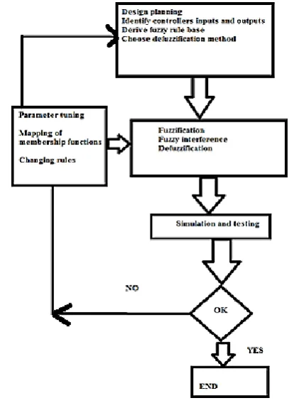
[image:3.595.324.528.72.356.2]Fuzzy Logic Controller (FLC) is proposed for the lateral control system and in this section it is described in detail. The concept of Fuzzy Logic Controller (FLC) was conceived by LotfiZadeh, a professor at the University of California at Berkley.It was not presented as a control methodology, but as a way of processing data by allowing partial set membership rather than crisp set membership or non-membership.FLC is a problem-solving control system methodology that will act as a feedback controller which is programmed to accept noisy, imprecise input so that it can be implemented in systems ranging from simple, small, embedded micro-controllers to large, networked, multi-channel PC or workstation-based data acquisition and control systems.FLC's approach to control problems mimics how a person would make decisions, only much faster. When idea of fuzzy logic is applied to control, it is generally called as ' fuzzy control. Fuzzy control is the first ever application known to which fuzzy logic is applied. The fuzzy controller is composed of four elements. These are fuzzification, rule base, inference mechanism and defuzzification. A flow chart which shows the designing steps of a fuzzy control system is given in fig 3,
Figure 3. The basic representation of fuzzy controller design methodology
The crisp inputs error and change in error are converted to fuzzy membership value on the fuzzy subsets negative big (NB), negative small (NS), zero (ZZ), positive small (PS), positive big (PB) We are using a four input two output fuzzy controller. The inputs are roll error, rate of change of roll error, yaw error and rate of change of yaw error. The outputs are control signal response for yaw and roll angles respectively. The membership functions of all the four inputs and two outputs are given
below:-3.1 Yaw error input
[image:3.595.316.538.570.705.2]The input “Error” consists of the following seven membership functions :-Big Negative Error (BN): Negative Error (N),Small Negative Error (SN),No Error (Z),Small Positive Error (SP),Small Positive Error (P) Big PositiveError,(BP).
3.2 Rate of change of yaw error input
[image:4.595.317.540.80.220.2]The “Rate Of Error” input, which represents the rate of the error input, consists of five membership functions. Big Negative (BN)Small Negative (NE): Zero Acceleration (ZR): Small Positive (PE): Big Positive (BP):
Figure 5 Rate of change of yaw error membership function
3.3 Roll error input
The input “Error” consists of the following five membership functions Big Negative Error (NB),Small Negative Error (NS.),No Error (ZZ.),Small Positive Error (PS).Big Positive Error (PB)
Figure 6Roll error membership function
3.4 Rate of change of roll error input
[image:4.595.54.290.95.295.2]The “Rate Of Error” input, which represents the rate of the error input, consists of five membership functions.Big Negative (NB): Small Negative (NS): Zero Acceleration (ZZ)Small Positive (PS): Big Positive (PB)
Figure 7 Rate of change of roll error membership function
3.5 Yaw output membership function
[image:4.595.320.576.345.492.2]The output1 of the system consists of seven membership functions as:-Big Negative Angle (BNT),Normal Negative Angle (NNT),Negative Angle (NT),Zero Thrust (ZT): Positive Angle (PT):,Normal Positive Angle (NPT),Big Positive Angle (BPT)
Fig 8 Yaw output membership function
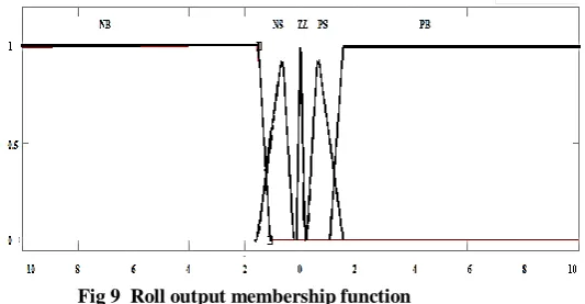
3.6 Roll output membership function
The output 2 of the system consists of five membership functions as:-Big Negative Angle (NB): Small Negative Angle (NS),Zero Thrust (ZZ): Small Positive Angle (PS): Big Positive Angle (PB):
[image:4.595.61.275.394.559.2] [image:4.595.317.584.579.717.2]These fuzzy membership values are used in the rule base in order to execute the related rules so that an output can be generated.A fuzzy control that has three hundred and ten rules is realized. These rules have been utilized in designing the controller and some rules are given below.
IF input1 is BN, input2 is BN, input3 is NB and input 4 is NB THEN output1 is BNT and output2 is NB
IF input1 is BN, input2 is BN, input3 is NB and input 4 is NS THEN output1 is BNT and output2 is NB
IF input1 is BN, input2 is BN, input3 is NB and input 4 is ZZ THEN output1 is BNT and output2 is NS
IF input1 is BN, input2 is BN, input3 is NB and input 4 is PS THEN output1 is BNT and output2 is NS
IF input1 is BN, input2 is BN, input3 is NB and input 4 is PB THEN output1 is BNT and output2 is ZZ
IF input1 is BN, input2 is BN, input3 is NS and input 4 is NB THEN output1 is BNT and output2 is NB
And so on…..
An inference mechanism imitates the expert’s decision making in interpreting and applying knowledge about how best the plant can be controlled. A defuzzification interface converts the conclusions of the inference mechanism into the crisp inputs for the process.
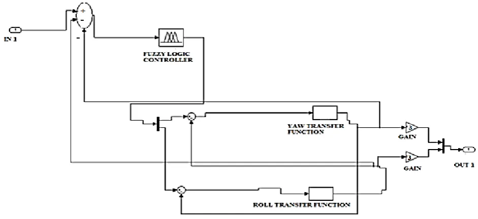
4 APPLICATION AND RESULTS
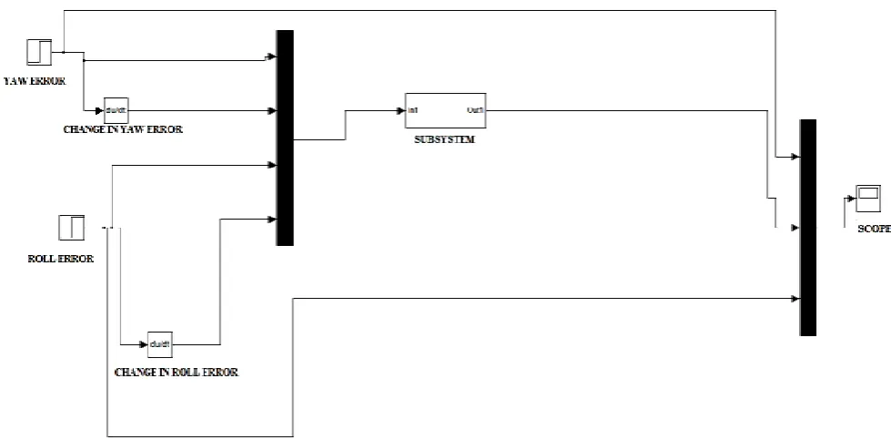
An aircraft lateral control system is simulated using FLC and the related simulation results are presented and discussed. Matlab/Simulink model block diagram of this system is shown in Fig. 11.The subsystem is shown in fig 12. In this system we had taken the cross-coupling effect of yaw and roll on each other. Matlab/Simulink blocks are interconnected to get the required cross coupling. Figure 10 shows the response of the system to standard step input. Two input steps are given, one with a magnitude of 1 unit and other with 2 units to differentiate the responses obtained for yaw and roll. The red plot shows the yaw control signal output and the blue plot
[image:5.595.57.547.502.743.2]shows that of roll. In yaw response there is less overshoot and oscillations compared to roll response.
Figure 10. The response of the system for yaw and roll
5 CONCLUSIONS
In this paper, the model of an aircraft lateral control system is designed in Matlab/Simulink environment and control methods were proposed. The effect of roll control surface on yaw and vice versa is also taken into consideration. The system will consider the cross coupling between the transfer functions so it will be more efficient and accurate than separate controller designsUse of fuzzy controller will result in an excellent overall response of the system.Reduction in oscillations and making the design more stable with less settling time will be our future work. The future work also includes testing and verifying the design in real time
Fig 12. Subsystem for lateral controller
6 REFERENCES
[1] R. C. Nelson, 1998, Flight Stability and Automatic Control, McGraw Hill, Second Edition.
[2] Lucio R. Riberio and Neusa Maria F. Oliveira, “UAV Autopilot Controllers Test Platform Using Matlab/Simulink and X-Plane”, 40th ASEE/IEEE Frontiers in Education Conference, October 27-30, 2010, Washington, DC.
[3]M. Ali Usta,ÖmürAkyazı and SefaAkpınar “Aircraft Roll Control System Using LQR and Fuzzy Logic Controller”,2011 IEEE,978-1-61284-922-5/11/26.00
[4] Nurbaiti Wahid and MohdFua’adRahmat, “Pitch Control System Using LQR and Fuzzy Controller”, 2010 IEEE Symposium on Industrial Electronics and Applications (ISIEA 2010), October 3-5, 2010, Penang, Malaysia (01.03.2011)
[5] Vishnu G Nair,Dileep M V,V I George,“Aircraft Yaw Control System using LQR and Fuzzy Logic Controller”,International Journal of ComputerApplications (0975 – 8887)Volume 45– No.9, May 2012
[6] Mıchael V. Cook, 2007, Flight Dynamics Prıncıples, Elsevıer, Second Edition.
[7]Matilde Santos, Victoria LópezFrancisoMorata, “Intelligent Fuzzy Controller of a Quadrotor”,2010 IEEE978-1-4244-6793-8/10/$26.00
[8] Le Zhang1,2, Shaojie Bi2, Hong Yang2,”Fuzzy-PID Control Algorithm of the Helicopter Model Flight
Attitude Control”, 978-1-4244-5182-1/10/$26.00 _c 2010 IEEE
[9]Nurbaiti Wahid, NurhaffizahHassan,”Self-tuning Fuzzy PID Controller Design for Aircraft Pitch Control”,978-0-7695-4668-1/12 $26.00 © 2012 IEEE
[10]Zhichao Liu, ZouhairChoukri el haj, and HongboShi ,“Control Strategy Design Based on Fuzzy Logic and LQR for 3-DOFHelicopter Model”,978-1-4244-7050-1/10/$26.00 2011IEEE
[11]Joshué Pérez, Vicente Milanés, and Enrique Onieva,” Cascade Architecture for Lateral Control inAutonomous Vehicles”, IEEE TRANSACTIONS ON INTELLIGENT TRANSPORTATION SYSTEMS, VOL. 12, NO. 1, MARCH 2011
[12] W. S. WijesomaK. R. S. KodagodaE. K. Teoh,”Stable Fuzzy State Space Controller for Lateral Control of an AGV”,Journal of VLSI Signal Processing Systems archive Volume 32 Issue 1/2, August-September 2002 Pages 189 – 201
[13] José E. Naranjo, Carlos González, Ricardo García, and Teresa de Pedro, “Using Fuzzy Logic in Automated Vehicle Control”, 1541-1672/07/$25.00 © 2007 IEEE intelligent systems
[14] Mohammed oudghirI, Mohammed chadl, Ahmed el hajjaji,”Lateral Vehicle Velocity Estimation Using Fuzzy Sliding Mode Observer”, proceedings of15th Mediterranean conference on control and automation,july 27-29,2007,Athens,Greece