InProceedings of the First IEEE International Conference on Pervasive Computing and Com-munications (PerCom 2003), pages 216–223, Dallas-Fort Worth, USA, March 2003. © IEEE.
A High Performance Privacy-Oriented Location System
Mike Hazas
∗Laboratory for Communication Engineering
University of Cambridge
Andy Ward
Ubiquitous Systems Limited
[email protected]
Abstract
Many mobile applications can be greatly enhanced when provided with the locations of people and devices. Ultra-sonic location systems have been shown to supply location information with centimeter accuracy at high update rates. Such high-performance systems, however, have relied upon a centralized or coordinated architecture, preventing the user from being in control of how their location informa-tion is handled and thus giving rise to privacy concerns.
In this paper we present a privacy-oriented location sys-tem allowing users with mobile ultrasonic receivers to as-certain their position autonomously. We formulate a method of operation for the system, detail its implementation in a small office, and characterize the performance of the sys-tem. The utilization of broadband ultrasound makes it pos-sible for the privacy-oriented location system to have com-petitive accuracy and high update rates, while allowing the user to be in direct control of their location information.
1. Introduction
To meet the needs of mobile and context-aware appli-cations that depend on location information, a number of positioning systems have been developed [4]. Much re-search on in-building context-aware applications and their associated location systems has focused on the office envi-ronment. Applications of these systems include receptionist aids, mobile desktop control, nearest-printer services, and augmented reality. For such applications, ultrasonic loca-tion systems have been applied because they can reliably provide fine-grained location data at high update rates [1].
To achieve this level of performance while tracking many people and devices, current indoor ultrasonic loca-tion systems require centralized or coordinated architec-tures, wherein data is gathered and locations are calculated, stored, and disseminated by a centrally-controlled service. Centralized systems might be deemed acceptable for some
∗Mike Hazas is now affiliated with Lancaster University, and can be contacted there.
environments, such as offices and research labs. If it can be assumed that location data will not be shared with outside parties, and will not be used to “spy” on employees, users may consent to having their location data managed by a cen-tral service. By doing so they can benefit from additional convenience and functionality afforded by context-aware applications distributed throughout their environment.
However, user privacy becomes more critical when pub-lic areas, such as museums, supermarkets, or government buildings, are to be equipped with location systems [5]. Examples of indoor applications in public spaces that uti-lize fine-grained location data are electronic tour guides, moving maps, and environmental resource discovery. With many different public buildings, each having its own track-ing infrastructure, it might be harder to guarantee that centrally-administered location data will be handled appro-priately.
Ultrasonic location systems which avoid centralized ad-ministration of location data have previously been devel-oped [8, 10]. However, these systems lack the update rate of centralized ultrasonic location systems. This is because the systems suffer from fundamental multiple access problems; efforts must be made to ensure that transmitters broadcast at different times, mandating compromises in aspects of sys-tem performance.
In this paper, we present a privacy-oriented ultrasonic location system which can achieve accuracies and update rates competitive with centralized systems. First, we review previous work on ultrasonic location systems, and propose a novel privacy-oriented location system. We then discuss the principles of the system in detail, including its architecture, signal structure, and positioning methods. Finally, we de-scribe a prototype implementation of the proposed system, and we characterize its performance.
2. Related work and motivation
be-tween the transmitter and receiver by the speed of sound in air. A number of propagation delays are collected between fixed transmitter or receiver units with known locations, and a mobile unit with an unknown location. By using algo-rithms based on the principles ofmultilateration, the loca-tion of the mobile unit can be found. Either ultrasonic re-ceivers are placed at known locations in the environment and transmitters are worn by people or affixed to objects to be tracked, or vice versa.
For example, in theBatsystem [1], a small tag attached to a person or object sends a single, uncoded ultrasonic pulse when radio-triggered by a central system. A net-work of ceiling receivers gathers pulse times-of-flight, and the system uses them to compute a 3D position estimate for the tag. The radio trigger serves to accurately synchro-nize the transmitter and receivers, and is coded with the tag’s identifier to prevent multiple tags from transmitting simultaneously—were this to occur, receivers could not as-cribe the uncoded ultrasonic signals to the correct tags. 95% of the readings are accurate to within several centimeters, and for a single tag, an update rate of 50 Hz is theoretically possible. However, the storage and dissemination of loca-tion informaloca-tion is centrally controlled and administered. Users must trust that the data will be handled responsibly.
TheConstellationsystem [2] works in the inverse way. A mobile unit with several ultrasonic receivers triggers a surrounding infrastructure of transmitters with an infrared signal. The transmitters, placed at fixed, known points in the environment, react to the infrared signal by emitting an ultrasonic pulse. The ultrasonic pulse time-of-flight mea-surements then allow the mobile unit to calculate its own position with accuracies of 5 mm.
2.1. Privacy-oriented systems
Ultrasonic location systems which are meant to allow sufficient security and control for the privacy-conscious user should have two properties: (1) a user’s presence is not advertised, even anonymously, and (2) entities outside of the user’s control are not entrusted with gathering sig-nal times-of-arrival or with calculating the user’s location; otherwise, these entities may relay that data to other parties without permission.
In order to have the first property, the location system should be designed such that mobile units do not need to emit any sort of detectable signal. By detecting emission of a signal, an observer might be able to infer the number of users present in an area. To have the second property, a mo-bile unit must use its own sensors to detect ranging signals broadcast from places in the environment, thus avoiding re-liance on external sensing devices. Additionally, the mobile unit must have knowledge of the surveyed locations of the environmental transmitters, so that it may calculate its
posi-tion autonomously using the times-of-arrival it gathers. Neither of the systems presented above have both of these properties—however, some work has already been done in this area.
2.1.1. Cricket. In theCricketsystem [8], units called
bea-cons are placed on the ceiling. Each beacon periodically emits an identifying radio signal and an uncoded ultrasonic pulse simultaneously. Users carry a mobile receiver called alistener. When a listener detects a radio signal, it mea-sures the relative time-of-arrival (the time-of-flight) of the corresponding, slower ultrasonic pulse. Beacons only trans-mit four times each second to minimize the probability that two transmission windows for nearby beacons overlap— this would make it impossible for a listener to match an incoming ultrasonic pulse to its identifying radio signal.
In one set of experiments with Cricket [9], ultrasonic pulse times-of-flight from four beacons in a room were used to estimate the listener’s 3D position. The mode of twenty-five distance samples from each beacon was used as the ac-tual transmitter-to-receiver distance, in order to minimize the effects of reflections and environmental ultrasonic noise. Tests were run with a listener in four different locations, yielding 3D accuracies between 5 and 25 cm. Since twenty-five distance samples were gathered from each beacon, a single location update would take an average of over five seconds to produce.
2.1.2. Low-cost indoor positioning system. Randell and
Muller describe a system [10] which allows wearable and mobile computers to autonomously compute their position. Four ultrasonic transducers are placed at the corners of a square on the ceiling, and are wired to a controller. The controller sends a radio trigger, and then issues an ultra-sonic pulse from each of the four transducers in succession. A mobile receiver unit, synchronized by the radio trigger, measures the ultrasonic pulse times-of-flight, from which it estimates its location with 3D accuracies between 10 and 25 cm. The update rate of the system is several hertz.
2.2. Enhancing privacy-oriented systems
Compared to a location system such as the Bat, the privacy-oriented systems have far slower update rates. Their performance is limited because sufficient time must be al-lowed for each ranging signal transmission to ensure that receivers can match the signal to its originating transmitter. All the above location systems use narrowband ultra-sonic signals, typically uncoded pulses.1Because these
sig-nals are uncoded, their identity must be conferred by other wireless means, such as the radio signal accompanying the
1Piezoceramic ultrasonic transducers, such as those used in the Bat and
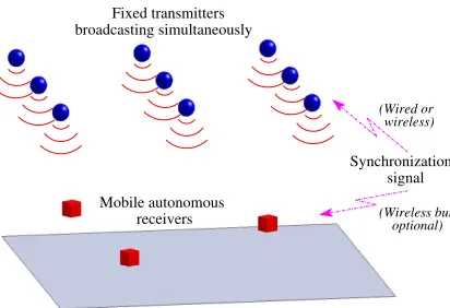
Synchronization signal Mobile autonomous
receivers Fixed transmitters broadcasting simultaneously
(Wired or wireless)
[image:3.612.64.270.69.210.2](Wireless but optional)
Figure 1. General system architecture
ultrasonic pulse in the Cricket system. To ensure that ul-trasonic pulses can be correctly identified by receivers, the systems must arrange that two pulses are never in flight in the same area simultaneously, thus limiting the rate at which ranging signals can be sent.
We propose below a new privacy-oriented system which utilizes broadband ultrasonic transmitters and receivers to avoid the above limitations. With a broadband ultrasonic channel, multiple access signals can be employed. Al-though we have previously described a broadband central-izedsystem which has some similar attributes [3], the sys-tem presented in this paper has a fundamentally different operation, and affords new advantages for privacy-oriented location awareness.
3. System principles
In this section, we discuss the architecture, signal-ing scheme, and positionsignal-ing algorithms of the proposed privacy-oriented broadband ultrasonic location system.
3.1. Architecture
Figure 1 shows the architecture of the proposed sys-tem. Broadband ultrasonic transmitters placed at fixed lo-cations on the ceiling simultaneously broadcast ranging sig-nals. The transmitters emit their ranging signals at well-defined times, and are synchronized using a wired or wire-less link. Mobile devices equipped with broadband ultra-sonic receivers are carried by users and attached to objects, and detect the times-of-arrival of the ultrasonic ranging sig-nals. Each device can independently compute its location, using the detected signal times-of-arrival and the known 3D coordinates of the fixed transmitters. The mobile units do not rely on outside entities to perform measurements or lo-cation calculations, and do not advertise their presence.
3.2. Signal structure
Since all the fixed transmitters are active simultaneously, their signals must be coded in such a way that mobile re-ceivers can distinguish between them. Solutions to this problem include direct sequence spread spectrum, code di-vision multiple access (DS/CDMA) and frequency-hopped signals—this paper considers DS/CDMA signal structures.
DS/CDMA signals can be created by using binary Gold codes to phase modulate a carrier frequency [12]. DS/CDMA ranging signals based on Gold codes are used in the Global Positioning System (GPS) [7]. All GPS satel-lites constantly transmit on the same carrier frequency, each modulating the carrier by its unique Gold code. A GPS re-ceiver unit measures the signal times-of-arrival from multi-ple satellites and estimates its position.
Similarly, Gold codes can be used to spread the spectrum of the transmitter ranging signals in an indoor ultrasonic lo-cation system. A unique Gold code can be assigned to each fixed environmental transmitter, allowing mobile units to di-rectly distinguish between their ranging signals. However, by applying the Gold coding to an ultrasonic carrier, the sig-nal energy is spread over a wide range of frequencies, and so the coded signals must be sent and received using ultra-sonic transducers with a wide bandwidth.
Each mobile unit can locally generate the signal it might expect to see from each transmitter, since it has knowledge of the Gold codes in use. The locally-generated signals are correlated against the incoming ultrasonic signal. A large peak in a correlated sequence is interpreted as a successful detection, enabling a time-of-arrival to be deduced from the time offset of the peak correlation. This time-of-arrival can then be used in positioning calculations.
The rate at which time-of-arrival estimates can be gener-ated is dependent on the length of the Gold code being used. Longer codes require longer correlation times, and result in lower update rates.
3.3. Positioning methods
This section describes two methods by which signal times-of-arrival can be used to calculate the mobile unit’s position, each method associated with a different mode of receiver operation.
3.3.1. Conventional multilateration. Synchronous
re-ceivers know when ranging signals depart from transmit-ters, and can directly measure the signal times-of-flight. Us-ing an estimate of the signal’s propagation speed, a trans-mitter-to-receiver distance can then be calculated.
specifically, a roaming receiver’s location(u, v, w)can be
related to the distance measurementdito a given transmit-teri, and the transmitter’s surveyed 3D location(xi, yi, zi). For a set of transmitter-to-receiver distances the relationship is expressed as
di=
p
(u−xi)2+ (v−yi)2+ (w−zi)2. (1) At least three transmitter-to-receiver distances are needed in order to perform multilateration. Using four or more distances allows an estimate of the standard error of the location result to be calculated. The standard error can be used to represent how well all the distances agree with the location result produced by the multilateration process.
Synchronous units tend to produce good location results, since the time-of-flight measurements allow reliable and accurate estimation of the true transmitter-to-receiver dis-tances. However, a wireless synchronization signal must be sent to the mobile unit to guarantee synchronous operation.
3.3.2. Pseudoranging. Asynchronous receivers do not
have explicit knowledge of when ranging signals depart from transmitters. Rather, they only know when transmit-ters send their signalswith respect to one another. With this knowledge, it is possible for a receiver to gather a number of times-of-arrival and calculate its position, despite the fact that it cannot measure signal times-of-flight directly.
Since the transmitter-to-receiver distances are unknown, conventional multilateration cannot be applied. However, a receiver can pick an arbitrary point in time from which to reference its signal time-of-flight measurements. Assuming knowledge of the times when transmitters broadcast relative to one another, the receiver can create a set ofpseudoranges. Pseudoranging is also performed by GPS receivers. The pseudoranges are not the actual transmitter-to-receiver ranges; instead the gathered pseudoranges have an equal offset from the true transmitter-to-receiver distances [7]. The distance offset is directly related to the difference be-tween the time at which the transmitters began sending their ranging signals and the time arbitrarily chosen by the re-ceiver to begin taking data. This time differential is known as thereceiver clock offset.
If the clock offset is negative, then the time arbitrar-ily chosen wasbeforethe transmitters began sending their ranging signals, and the pseudoranges are longer than the true ranges. If the clock offset is positive, then the receiver’s chosen time is late, and the pseudoranges are too short.
The distance offset due to receiver clock offset must be incorporated in the model used in the multilateration pro-cess. The relationship of equation 1 thus becomes
˜ di=
p
(u−xi)2+ (v−yi)2+ (w−zi)2−dc, (2)
wheredcis the distance offset common to all pseudoranges
andd˜iis the pseudorange to a particular transmitter. To
per-form multilateration, four pseudoranges are required, since the unknown distance offset must be estimated in addition to the receiver’s 3D coordinates. If a measure of the stan-dard error is desired, five or more pseudoranges are needed. Asynchronous receivers have the disadvantage that they must gather one more signal time-of-arrival in order to com-pute a location. Also, their location estimates tend not to be as accurate, since the algorithm must fit four parameters to the data instead of three (equation 2). However, the advan-tage of asynchronous receivers is that they do not need the capability to receive a wireless synchronization signal.
3.4. Transmitter synchronization
For both of the positioning methods described in sec-tion 3.3, receivers must have knowledge of the relative times at which the transmitters send their ranging messages. This implies that each transmitter must also have knowledge of the time at which it is to begin sending, relative to the other transmitters. Of course, all of the transmitters in one ul-trasonic space could be interconnected, allowing them to share a common clock. However, this makes the installation of large-scale systems labor-intensive, since deployment of ceiling transmitters is more difficult.
One alternative is to deploy the transmitters in an ad hoc fashion, requiring only that they be affixed to a location and surveyed. A system-wide wireless beacon would then be provided, allowing transmitters to synchronize the transmis-sion of their ranging messages. Mobile receivers could also use the system-wide beacon to operate synchronously.
As with many infrastructural systems, there is a trade-off between the costs of initial set-up and regular maintenance. Their relative overheads will depend on the way in which the transmitters in the environment are powered and syn-chronized. For example, transmitters which are powered by mains and synchronized using a wired link will require a labor-intensive installation, but very little upkeep. On the other hand, battery-powered transmitters which use radio signals for synchronization would have a simple installa-tion involving only placement and surveying, but periodic battery replacement for the transmitter units will be needed.
4. Prototype implementation
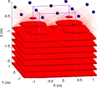
(a) Modeled transmitter radiation (b) Areas covered by at least four transmitters
Figure 2. Multiple cell coverage
the receiver are generally low [3]. DS/CDMA signal struc-tures are appropriate for this channel, because they make high processing gains to counter low signal-to-noise con-ditions more easily attainable than other multiple-access methods, such as frequency hopping.
To implement a system with the architecture described above, fixed Dolphin transmitter units were connected, via a signal synthesis card, to a workstation PC which gener-ated the spread spectrum ranging messages. A Dolphin re-ceiver, acting as the mobile unit, was connected via a data acquisition card to the same PC, which performed the cor-relation detection and position calculation operations.2 A
temperature sensor was also connected to the PC, allowing the speed of sound in air to be estimated accurately.
The spread spectrum ranging messages sent by the trans-mitters consist of a 50 kHz carrier, phase modulated by a 511 bit Gold code. The Gold code was applied at a rate of 20 kHz, giving the ranging message a duration of approxi-mately 25 ms. Each transmitter was assigned a unique Gold code. The transmitters sent their ranging messages cycli-cally, meaning that the beginning of one 511 bit code cycle immediately followed the end of the previous cycle. The transmitters were configured to begin their ranging message cycles simultaneously.
Transmitter placement. It is important to maximize the
number of transmitters from which a mobile unit can re-ceive signals at any point in space—for each positioning method in section 3.3, there is a minimum number of signals that must be resolved to compute the mobile unit’s position,
2In the prototype implementation, therefore, the PC is involved with
both the fixed infrastructure and the mobile receiver, although these func-tions are logically distinct.
and any further resolved signals can be used to increase the accuracy of the position solution.
The placement of ceiling transmitters has a large effect on the number of signals a roaming receiver will be able to resolve. Our approach to transmitter placement was to arrange several transmitters on the ceiling to cover a small volume, designated aunit cell. Larger volumes could then be covered by adjacent, tessellating cells.
The unit cell contains four transmitters, positioned at the centers of the vertices of a 1.2 m square. Typical room sizes will require a tessellation of the 1.2 m×1.2 m cells. Fig-ure 2(a) depicts the situation where there are multiple adja-cent cells.3 As shown by figure 2(b), the area covered by
several transmitters (i.e. the area of operation of the system) increases with distance from the ceiling.
Moreover, the tessellation of cells means that many posi-tions in a room may benefit from coverage from more than four transmitters, since additional coverage is provided by transmitters in adjacent cells. This is demonstrated by fig-ure 3, which shows a detail of the transmitter coverage for two different heights.
5. Experiments
Tests were conducted in order to assess the accuracy of the privacy-oriented location system. This section describes the test procedure, presents the measurement results, and evaluates the safety of the system.
3The transducers fitted on the Dolphin transmitters have a response
4
6
7
8
6
6
6
8
7
4
7
4
7
4
4
8
8
(a) 80 cm below the ceiling
8
12
8
8
8
10
10
10
10
[image:6.612.113.484.88.239.2](b) 100 cm below the ceiling
Figure 3. Multiple cell coverage, showing number of transmitters covering each region
5.1. Test procedure
A Dolphin receiver was placed at each of a number of test points in a small (3.5 m×2.6 m) office. Seven transmit-ters were placed on the ceiling and arranged on a 1.2 m grid to form two adjacent unit cells covering that area. The test points were comprised of sixteen points on a 0.5 m grid, at each of four different heights (approximately 0.8 m, 1.3 m, 1.8 m, and 2.2 m from the ceiling). Measurements were taken to assess system performance, for both synchronous and asynchronous receiver operation.
Five hundred readings were taken at each of the sixty-four locations. For the location results, it was required that the standard error be computed so that a returned position could be assessed in terms of how well the signal times-of-arrival “fit” together. In order to guarantee that the standard error could be calculated, four transmitters had to be de-tected by the synchronous receiver, and five transmitters by the asynchronous receiver. Readings in which the receiver detected too few transmitters were discarded. In addition, location results having a high standard error were discarded.
5.2. Results
Figure 4 shows the error distributions of the returned lo-cation readings for both a synchronous and an asynchronous receiver. Figure 5 shows the fraction of readings returned by receivers against their distance from the ceiling.
5.2.1. Accuracy. As the results show, the 3D accuracy of
a synchronous receiver is better than 5 cm in 95% of cases. This is similar to the performance of centrally coordinated location systems, and is better than the accuracy of both of the privacy-oriented systems described in section 2.1.
The 95% accuracy of an asynchronous receiver is much worse—over 25 cm. This is because the nearly copla-nar placement of ceiling transmitters creates an interdepen-dency between two of the estimated parameters—the dis-tance offset dc and the vertical component of positionw
(equation 2). Figure 4(b) shows clearly that the vertical er-ror component contributes far more to the 3D position erer-ror than the horizontal error component. However, many indoor context-aware applications require only that the horizontal positions of people and objects be fine-grained; the verti-cal component tends to be less significant. Although the asynchronous receiver’s 3D accuracy is much worse than that provided by a coordinated location system, it can still provide location data with a horizontal 95% accuracy of ap-proximately 8 cm.
5.2.2. Fraction of readings returned. The average
frac-tion of readings returned by the asynchronous receiver over the test space was 48%, as opposed to 67% for the syn-chronous receiver. This is because the asynsyn-chronous re-ceiver needs to detect at least five signal times-of-arrival to calculate its location and an error estimate, whereas the synchronous receiver only requires four. Thus, the asyn-chronous receiver had to identify five of the seven available transmitter signals.
0 1 2 3 4 5 6 7 8 0
10 20 30 40 50 60 70 80 90 100
Position error (cm)
Percentage of readings with error less than abscissa
Horizontal Vertical 3D
(a) Synchronous receiver
0 5 10 15 20 25 30 35 40
0 10 20 30 40 50 60 70 80 90 100
Position error (cm)
Percentage of readings with error less than abscissa
Horizontal Vertical 3D
[image:7.612.94.508.83.237.2](b) Asynchronous receiver
Figure 4. Accuracy of location estimates
close to the ceiling could be easily remedied by placing an additional transmitter in the middle of each unit cell.
0.8 1 1.2 1.4 1.6 1.8 2 2.2 2.4 2.6 0
10 20 30 40 50 60 70 80 90 100
Receiver distance from ceiling (m)
Percentage of readings returned
[image:7.612.75.261.349.498.2]Synchronous receiver Asynchronous receiver
Figure 5. Receiver height limitations
5.2.3. Update rate. Because the Gold code ranging
mes-sage cycles last approximately 25 ms, the location update rate of each mobile unit performing back-to-back correla-tion operacorrela-tions would 40 Hz, for both the synchronous and asynchronous cases. Again, this is superior to the privacy-oriented systems outlined in section 2.1.
5.3. Safety evaluation
Acoustic measurements were taken in the room with all seven transmitters active. Total ultrasonic sound pressure level varied from 69 dB near the floor to 87 dB at 20 cm be-low the ceiling. These levels fall well within safety
guide-lines, the most conservative of which require that levels not exceed 100 dB throughout most of the ultrasonic range [6].
6. Considerations for a deployable system
Receiver signal processing. In the experiments presented
in this paper, Fast Fourier Transform (FFT) operations run-ning in software on the workstation PC were used to cor-relate the received signals with the expected spread spec-trum waveforms. Since FFTs are computationally expen-sive, specialized hardware correlators would most likely be employed in a deployable version of the mobile receiver unit. Miniaturization of an integrated receiver unit is cer-tainly feasible—GPS receivers, which perform essentially the same operations at much higher speeds, have been suc-cessfully engineered to fit into PCMCIA cards.
When many transmitters are co-located, DS/CDMA sys-tems often use power control to avoid near-far prob-lems (interference due to imbalances in transmitter signal strengths as seen by the receiver). Transmitter power con-trol would be impractical in a privacy-oriented location sys-tem because each receiver sees a signal of different strength from each transmitter. However, successive interference cancellation processing can be used to correct for signal strength imbalances at the receiver if near-far issues arise [11].
Transmitter power provision. In situations where ranging
changes to the prototype units to provide low power oper-ation, including component selection and operating voltage reduction, have been proposed elsewhere [3].
Code reuse. If the location system is to cover a large
build-ing, the number of transmitters can easily exceed the num-ber of Gold codes available, which depends on the code length. One response would be to increase the length of the Gold codes being used, but this would decrease the achiev-able update rate of the system.
This situation forces the reuse of codes, wherein several transmitters in the system broadcast using the same Gold code. To avoid interference, transmitters assigned identi-cal Gold codes should not be placed in the same ultrasonic space. Furthermore, with multiple transmitters in the sys-tem broadcasting the same code, it is no longer possible for receivers to directly associate a single transmitter’s identity and known coordinates with a unique Gold code. In this case, it is necessary for the transmitters to uniquely identify themselves using some other method.4
Additional information can be sent over the broadband channel by further phase modulating the transmitted Gold code sequences with a sequence of data bits, which are then decoded at the receiver. This strategy could be applied in a large-scale broadband ultrasonic location system. Together with the Gold code itself, a short sequence of transmitted bits would allow a receiver to uniquely identify a transmit-ter. Alternatively, a transmitter can simply send its 3D co-ordinates as the modulating bit stream.
7. Conclusions
In this paper, we have proposed a privacy-oriented broadband ultrasonic location system. It performs spread spectrum ranging using Gold codes to allow simultaneous multiple access. Positioning algorithms were presented for both synchronous and asynchronous receivers, and methods were outlined for large-scale deployment of the proposed system.
Our experiments show that broadband ultrasonic loca-tion systems can provide accurate and timely informa-tion for privacy-sensitive context-aware applicainforma-tions. The broadband nature of our solution means that many transmit-ters can broadcast simultaneously in the same room, since receivers can directly identify incoming ranging signals. Consequently, our system has a highly competitive accu-racy and a superior update rate when compared to previous privacy-oriented ultrasonic location systems.
4This is not necessary with GPS, where there are over a thousand
avail-able Gold codes in the chosen set, and only twenty-four satellites.
Acknowledgments
Mike Hazas is grateful to Andy Hopper for his contin-uing support, and to Robert Harle for his helpful thoughts on transmitter placement schemes. Thanks also go to James Scott and Frank Hoffmann for their comments on this paper. This material is based upon work supported under a U.S. National Science Foundation Graduate Fellowship.
References
[1] M. Addlesee, R. Curwen, S. Hodges, J. Newman, P. Steggles, A. Ward, and A. Hopper. Implementing a sen-tient computing system.IEEE Computer, 34(8):50–56, Aug. 2001.
[2] E. Foxlin, M. Harrington, and G. Pfeifer. Constellation: A wide-range wireless motion-tracking system for augmented reality and virtual set applications. InProceedings of the 25th
Annual Conference on Computer Graphics, pages 371– 378, Orlando, Florida, USA, July 1998.
[3] M. Hazas and A. Ward. A novel broadband ultrasonic loca-tion system. InProceedings of UbiComp 2002: Ubiquitous Computing, pages 264–280, G¨oteborg, Sweden, Sept. 2002. [4] J. Hightower and G. Borriello. Location systems for ubiqui-tous computing.IEEE Computer, 34(8):57–66, Aug. 2001. [5] M. Langheinrich. Privacy by design—principles of
privacy-aware ubiquitous systems. In Proceedings of UbiComp 2001: Ubiquitous Computing, pages 273–291, Atlanta, Georgia, USA, Sept. 2001.
[6] B. W. Lawton. Damage to human hearing by airborne sound of very high frequency or ultrasonic frequency. Contract research report, British Health and Safety Executive, 2001. Prepared by the Institute of Sound and Vibration Research. [7] R. J. Milliken and C. J. Zoller. Principle of operation of
NAVSTAR and system characteristics. InGlobal Position-ing System, volume 1, pages 3–14. The Insititute of Naviga-tion, Alexandria, Virginia, USA, 1980.
[8] N. B. Priyantha, A. Chakraborty, and H. Balakrishnan. The Cricket location-support system. InProceedings of the Sixth International Conference on Mobile Computing and Net-working (MobiCom), Boston, Massachusetts, USA, Aug. 2000.
[9] N. B. Priyantha, A. K. L. Miu, H. Balakrishnan, and S. Teller. The Cricket Compass for context-aware mobile applications. InProceedings of the Seventh International Conference on Mobile Computing and Networking (Mobi-Com), Rome, Italy, July 2001.
[10] C. Randell and H. Muller. Low cost indoor positioning sys-tem. InProceedings of UbiComp 2001: Ubiquitous Com-puting, pages 42–48, Atlanta, Georgia, USA, Sept. 2001. [11] A. J. Viterbi. Very low rate convolutional codes for
maxi-mum theoretical performance of spread-spectrum multiple-access channels. IEEE Journal on Selected Areas in Com-munications, 8(4):641–649, May 1990.