Behavioural specification and simulation of minimum
configuration computer systems.
GORTON, Ian.
Available from Sheffield Hallam University Research Archive (SHURA) at:
http://shura.shu.ac.uk/19708/
This document is the author deposited version. You are advised to consult the
publisher's version if you wish to cite from it.
Published version
GORTON, Ian. (1988). Behavioural specification and simulation of minimum
configuration computer systems. Doctoral, Sheffield Hallam University (United
Kingdom)..
Copyright and re-use policy
i
?3>0Hr
Sheffield City Polytechnic Library
ProQuest Number: 10697008
All rights reserved
INFORMATION TO ALL USERS
The quality of this reproduction is dependent upon the quality of the copy submitted.
In the unlikely event that the author did not send a com plete manuscript and there are missing pages, these will be noted. Also, if material had to be removed,
a note will indicate the deletion.
uest
ProQuest 10697008
Published by ProQuest LLC(2017). Copyright of the Dissertation is held by the Author.
All rights reserved.
This work is protected against unauthorized copying under Title 17, United States C ode Microform Edition © ProQuest LLC.
ProQuest LLC.
789 East Eisenhower Parkway P.O. Box 1346
Behavioural Specification and Simulation of Minimum Configuration Computer Systems
by
Ian Gorton BSc
A thesis submitted to the Council for National Academic Awards in partial fulfilment of the requirements for the degree of Doctor of Philosophy.
Sponsoring Establishment : Department of Computer Studies Sheffield City Polytechnic
Collaborating Establishment: Motorola (UK) Ltd.
■ M
^
i
ooif'fc
Af t O
Ian Gorton : Behavioural Specification and Simulation of Minimum Configuration Computer Systems
Abstract
The ultimate goal of Computer-Aided Design research in the area of digital circuits is the automatic synthesis of a complete solution from a behavioural specification. This thesis describes an attempt to attain this ideal in the more limited realm of designing single-board control
systems, constructed from general-purpose microprocessor components. The difficulties currently encountered in designing and implementing microprocessor control systems are outlined, and the architecture of an integrated,
knowledge-based design system is proposed as a method of overcoming these difficulties. The design system
encompasses both behavioural and structural design
functions. However, only the tools and techniques required to fulfil the behavioural design functions are considered in detail in this project.
A review of previous work in the field of automated digital circuit design and software and hardware specification
languages is presented. The major features of a novel language for specifying and simulating control system
behaviour' are then described, together with an intermediate design description notation, which facilitates the
generation of microprocessor assembly language code
directly from behavioural specifications. The design and implementation of a fast, generalised microprocessor simulation facility constructed from transputers is discussed, and its performance potential analysed. The
simulation facility enables the complete design for a given application to be tested, before any actual hardware
construction takes place. Finally, an evaluation of the behavioural specification, synthesis and simulation
techniques developed in this project is presented, and the benefits perceived from adopting such techniques are
summarised. Issues concerning the integration of these
techniques with the knowledge-based structural design tools are also dealt with, and suggestions for further
Acknowledgements
I would like to thank my supervisors Dr J.M.Kerridge, Dr B.Jervis and Dr J.Travis for their help and advice during the period leading up to this report.
Contents
1. Project Overview
1.1 Minimum Configuration Systems
1.2 The Design and Implementation of Minimum Configuration Systems
1.3 The Difficulties of System Design
1.4 A Solution to the Problems of MCS Design 1.5 Objectives
1.6 Summary 2. Related Work
2.1 Computer-Aided Design of Digital Systems 2.1.1 Introduction
2.1.2 The RT-CAD System 2.1.3 ULYSSES
2.1.4 Synapse 2.1.5 MAPLE 2.1.6 XCON 2.1.7 Others
2.2 Software Specification Techniques 2.2.1 Introduction
2.2.2 Phase of Applicability
2.2.2.1 Requirements Specification Languages
2.2.2.2 Design Specification Languages 2.2.2.3 Program Design Languages
2.2.3 Area of Application 2.2.4 Language Model
2.2.4.1 State-based Languages 2.2.4.2 Event-based Languages 2.2.4.3 Relational Languages 2.2.5 Desirable Features of Software
Specification Languages 2.2.5.1 Understandability 2.2.5.2 Analysability 2.2.5.3 Maintainability 2.2.6 Examples
2.2.6.1 VDM 2.2.6.2 Espreso
2.3 Hardware Description Languages 2.3.1 Introduction
2.3.2 Structural HDLs 2.3.3 Behavioural HDLs 2.3.4 Hardware Synthesis 2.3.5 Examples
2.3.5.1 Instruction Set Processor Specification (ISPS)
3. A Behavioural Specification Language For Minimum Configuration Systems
3.1 Language Requirements 3.1.1 Event-Based Model 3.1.2 Actions
3.1.3 Representation of Time Constraints 3.1.4 Formal Definition
3.1.5 Analysable 3.1.6 Executable 3.1.7 Familiarity 3.2 Language Basis 3.3 Language Features
3.3.1 Specification Structure 3.3.2 Channel Definitions
3.3.3 Service Routine Declarations 3.3.4 Control Section
3.4 An Example
3.5 Executing Behavioural Specifications 3.6 Conclusions
4. Generating Microprocessor Control Software from Behavioural Specifications
4.1 Introduction
4.2 Processor-Independent Assembly Language 4.2.1 Design Rationale
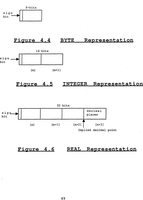
4.2.2 Language Features
4.2.2.1 Control Structures 4.2.2.2 Data Types
4.2.2.3 Operations
4.3 Compiling the BSL into Macro-Assembly Language 4.3.1 Overview
4.3.2 Pass One 4.3.3 Pass Two 4.3.4 Pass Three
4.4 The Implementation of Macro Instructions 4.4.1 Data Types
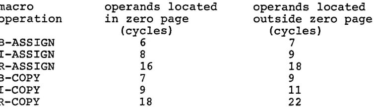
4.4.2 Operations
4.4.3 Control Structures
4.5 Processing the Macro-Assembly Language 4.6 Conclusions
5. Microprocessor System Simulation 5.1 System Design
5.2 Component Simulation 5.3 System Bus Simulation
5.3.1 Requirements 5.3.2 Address Bus 5.3.3 Data Bus 5.3.4 Control Bus
5.4 Implementation on a Single Transputer 5.5 Implementation on a Transputer Network
5.5.1 The Problem
5.5.2 Experimental Strategy 5.5.3 Experiments Performed 5.5.4 Discussion
6. Evaluation
6.1 Introduction
6.2 Applicability of the Behavioural Specification Language
6.2.1 Data Stream Applications 6.2.2 Discrete-state Controllers 6.2.3 Proportional Mode Controllers 6.2.4 A Problem
6.2.5 Evaluation
6.3 Evaluation of the Behavioural Simulation 6.4 Evaluation of the Macro-Assembler Language 6.5 Evaluation of the Microprocessor Simulation
Facility 6.6 Summary 7. Future Work
7.1 Integrating and Interfacing Behavioural and Structural Design Tools
7.1.1 Introduction
7.1.2 Design System Operation
7.2 Designing Transputer-Based Control Systems 7.3 Summary
8. Conclusions
Appendix A Occam and Transputers
Appendix B Behavioural Specification Language (BSL) Definition
Appendix C 6800 Implementations of Macro Operations
1^ Project Overview
1.1 Minimum Configuration Systems
Microprocessors have made a significant impact on all
aspects of control systems[1.1]. Direct digital control of machine processes has created production methods that are more reliable, economic and generally more efficient. The
low cost, flexibility and processing speed of control systems constructed from Large Scale Integration (LSI) components enables them to be applied economically to even the simplest control tasks[1.2], often replacing the need for complex hard-wired logic[1.3]. Such possibilities have led to a move away from centralised mainframe or
minicomputer control systems, towards decentralised control based upon many embedded microprocessors, each dedicated to performing a simple part of the whole control task[1.4].
In order to be cost-effective, or when the microprocessor is tightly coupled with other circuitry, it is often
desirable to design special printed circuit boards (PCBs) to implement the different system functions. In these cases, the microprocessor system can be viewed as merely one set of components amongst others on the board. Such systems do not normally require a disk system or visual display unit, and are consequently difficult to develop and test[1.5].
Many microprocessor-based control systems, whether sub-components of a large decentralised system, or a stand-alone dedicated control system, are typified by containing the minimum number of components required to perform the control task. Systems in this category usually comprise a microprocessor and clock, small amounts of
read-only and read-write memory and the capability to interface with the physical process being controlled. For this reason, such systems are referred to as minimum
printed circuit board. More formally, an MCS may be defined as any size system within the basic load limitation of the microprocessor concerned[1.6].
1.2 The Design and Implementation of Minimum Configuration Systems
The design and implementation of an MCS is a complex task, requiring a wide diversity of expertise from the system designer. The designer must have a thorough knowledge of all the issues involved, from individual component
characteristics to software design and implementation.
Once a requirements specification for the proposed control system has been finalised, a solution to the problem must be designed. The design describes how the processes in the specification are to be carried out. Such a design involves both the selection of a set of components and the design of the software routines needed to implement the solution. Decisions must be taken as to which functions to implement in hardware and which in software, and detailed algorithms and component interfaces must be specified[1.7]. The design is governed mainly by the performance levels required of the system in the specification, and the control functions that must be carried out[1.8].
The physical realisation of the design occurs during implementation. Software development and hardware construction may both proceed in parallel. When the
hardware and software have been separately tested, they can be brought together for system testing. It is almost
certain that some modifications and corrections will be necessary before the system satisfies its specification. However, if system testing reveals fundamental design errors, a considerable amount of redesign and
1.3 The Difficulties of System Design
There are three main stages during which errors may be introduced into an MCS design[1.5], These
are:-1. Interpretation
The requirements specification for the desired system may contain inconsistencies and ambiguities, which may lead the designer to make incorrect assumptions. Even complete
specifications may be misinterpreted. This may result in logical errors being introduced into the hardware and software design.
2. Hardware
The task of designing the hardware for an MCS comprises two related activities: component selection and component
interconnection. Component selection is complicated by the fact that many LSI components have the same functional characteristics but different operational characteristics. Further, components from one microprocessor family may not easily interface with components from others. Thus, in the absence of an integrated set of evaluation tools, the
designer must rely on previous experience to ensure that the chosen components can fully satisfy the specification.
Component interconnection is a well understood, mechanical task, which is tedious and prone to errors. It requires the designer to check through the individual component data sheets, in order to identify the precise connections
between them. Errors introduced during this process can be of a very subtle nature, making them difficult to locate during testing.
3. Software
assembler language of the microprocessor in use. This approach however does not lend itself to satisfying the goals of maintainability, portability and ease of
construction. These three requirements are best achieved by the use of a high-level language such as Pascal [1.11] or A D A [1.12]. These provide abstraction of control and data representation, and, coupled with modern compiling
techniques, can give a level of efficiency approaching that of handwritten machine code.
Still, high-level languages do not provide a complete
solution to the software development problem. Due to their general-purpose nature, they do not include constructs for accessing low-level processor facilities such as interrupts and input-output(1-0) interfaces. To achieve these,
assembler subroutines have to be created. These subroutines are, however, processor-dependent. Any change or upgrading of processor or system configuration will require all the assembler routines to be rewritten in the assembly language of the new target processor.
Further problems arise during software testing. The initial tests take place on a software development machine, not upon the target hardware configuration. This means that a software test harness needs to be built, which simulates the behaviour of the environment in which the control software is to operate. The important aspect of test
harnesses is that they are application specific, and do not form part of the final product. When the software seems to function correctly and is ready to be tested on the target hardware, the test harness becomes effectively obsolete.
Consequently, much effort is expended in designing, building and testing a prototype solution. Many of the errors located during testing may be simple implementation mistakes, which are relatively straightforward to correct. However, errors introduced during the design phase are often of a much more serious nature, and may only be
together[1.5] . For this reason, design errors can be costly and time-consuming to correct.
1.4 A Solution to the Problems of MCS Design
Clearly then, due to the lack of suitable techniques, the process of developing MCSs is complex and potentially
expensive. Therefore it seems there is a requirement for a set of integrated software tools, which can design and simulate both the hardware and software for MCSs from a high-level system specification. This approach would ensure that all serious design faults have been removed before implementation proceeds[1.5],
Given a specification of the hardware and software
requirements of a system, and knowledge of an appropriate set of components, the design system could construct a simulation of a possible solution. The simulation could then be evaluated and, if necessary, modified by the
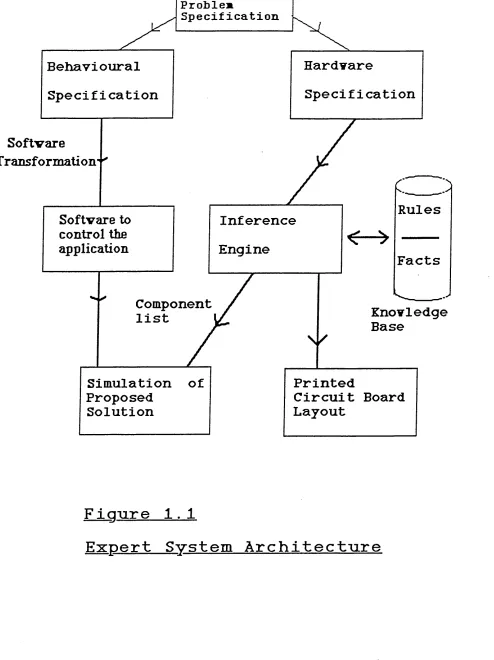
designer. When the simulation satisfies its specification, the design system could automatically generate the printed circuit board (PCB) layout for the solution, so that the implementation can begin. Figure 1.1 shows the proposed architecture of the design system.
The five major components of Figure 1.1
are:-1. Problem Specification
The specification mechanism employed must allow the designer to specify completely the structural (hardware) requirements of the system, together with the behaviour that the system is to exhibit (the software).
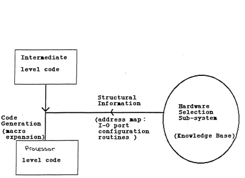
2. Software Generation
The behavioural specification must be analysed and
S oftvare
Transform ation' ^
Rules
Facts
Knovledge
Base
Component
list
Problem
Specification
Softvare to
control the
application
Simulation of
Proposed
Solution
Specification
Printed
Circuit Board
Layout
Behavioural
Specification
Engine
Inference
Figure 1.1
[image:16.612.44.538.25.685.2]the assembly language of the microprocessor chosen to implement the system.
3. Knowledge Base and Inference Engine
The knowledge base will contain factual data on LSI components, a collection of rules which govern their application, and a generalised functional simulation of each component. The inference engine will attempt to find a solution to a given problem by applying rules in the
knowledge base. The result of this process will be a configurable MCS.
4. Simulation
Individual component simulations will be stored in the knowledge base, and be combined when required to form simulations of the proposed MCSs. A language suitable for component description and simulation must be used to
construct simulations, together with hardware which
facilitates efficient simulation execution. If sufficiently fast ('almost* real-time) simulations can be generated, it may be possible to interface the simulation with the
physical system to be controlled.
5. PCB layout
The PCB layout for the final solution can be produced from the detailed data stored in the knowledge base.
The nature and operation of each of the above system components is diverse: each requires a fundamentally different set of techniques for its design and
implementation. For example, the hardware selection element of the system should greatly benefit from the use of expert system techniques[1.13]. The explicit definition in the knowledge base of the heuristics used to design MCSs should make the design system much simpler to implement, maintain
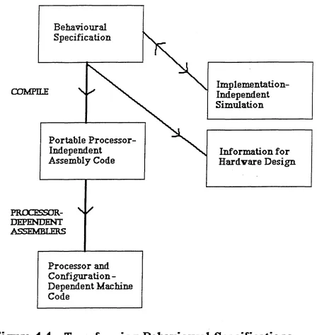
would be best constructed in a language which contains features appropriate for describing hardware.
The adoption of an integrated, rule-based approach to the design process has several potential advantages. Firstly, the high-level behavioural specification could be totally processor-independent, making it possible to automatically generate machine code for any given processor in the
knowledge base. Second, the expert system could select
appropriate components from its knowledge base, and perform the task of component interconnection. Given an extensive and regularly updated knowledge base, the expert system should perform the selection task at least as well as a human designer. Moreover, it should not be error-prone when configuring the system components. Third, a potential
solution could be evaluated early in the development cycle by comparing the behaviour of its simulation against the requirements specification. This allows the designer to be confident of the correctness of the design before any
implementation activity takes place.
1.5 Objectives
The work reported in this thesis describes asdtoj tools and techniques which can perform the synthesis and simulation of low-level machine code for an MCS from a design-level behavioural specification. No attempt is made to design or construct the knowledge base or inference engine of the expert system, as this work forms the focus of another research project. Only the interface and information interchange between the inference engine and the
behavioural specification system is considered in some detail.
language for MCSs, and presents the features of a language designed to meet these requirements. Chapter 4 explains how behavioural specifications can be automatically transformed into machine code implementations for particular
microprocessors. The structure and features of a
processor-independent assembly language which facilitates this transformation is also described. In Chapter 5, the design and construction of a generalised simulation
facility for MCSs is presented, and the performance of some example simulations is discussed. Through the use of
several examples, Chapter 6 attempts to evaluate the specification and simulation techniques described in the earlier sections. In this manner, a classification of applications where such techniques are primarily suitable is devised. Finally, Chapter 7 presents areas which may be considered for further work, and provides a detailed
outline design specification for the operation of the complete expert system.
1.6 Summary
Microprocessor systems are used widely to implement process control functions. The complexity of such control systems varies greatly. However, current hardware and software development tools do not facilitate fast prototyping and evaluation of possible solutions. Consequently any basic design errors carried through to prototype implementations are costly and time-consuming to correct. In an attempt to solve these problems, the essential elements of an
integrated design environment for minimum configuration systems have been presented. The design environment would allow applications to be described at a high-level,
relieving the designer of much detail. Simulations of possible solutions would be generated from system
References
1.1 House,C.H.:'Perspectives on Dedicated Control'. IEEE Computer, Dec 1980, vol 7, no 12, pp 35-48 1.2 Arnold,J.T. :'Simplified Digital Automation with
Microprocessors',ch.1, pp 2-10, Academic Press, New York 1979
1.3 Johnson,C.D.:'Microprocessor-based Process Control', ch.l, pp 1-32, Prentice-Hall, INC., New Jersey 1984
1.4 Simons,G.L. : 'Uses of Microprocessors',ch.4, N.C.C. Publications, 1980
1.5 Hudson,C. : 'Techniques for developing and testing microprocessor systems', Software and Microsystems, August 1985, Vol 18, No. 4, pp 81-92
1.6 Streitmatter,G.A. and Fiore,V. :'Microprocessors -Theory and Application1,ch.12, pp 219-253,
Reston Publishing Company, Virginia, 1979
1.7 'System Specification, Design and Implementation Tools', Dept, of Computation, University of
Manchester Institute of Science and Technology 1.8 Zaks,R. : 'Microprocessors',ch.9, pp 363-387,
SYBEX Inc, USA, 1977
1.9 Saxena,S. and Field,J.A.:'Portable Real-Time Software for 8bit Microprocessors', Software -Practice and Experience, 15, (3), 277-303 (1985) 1.10 Welsh,P.H.:'Managing Hard Real-Time Demands on
Transputers',Procs 7th Occam User Group Conference, Grenoble, 14-16 Sept 19 87
1.11 Jensen,K. and Wirth,N.:'Pascal User Manual and Report', Springer-Verlag, New York-Berlin, 1975 1.12 Buhr,R:'System Design with ADA', Prentice-Hall,
1984
2 Related Work
2.1 Computer-Aided Design of Digital Systems
2.1.1 Introduction
Many integrated Computer-Aided Design (CAD) systems have been developed to assist with the design of digital
systems. Existing CAD applications range from the development of mask descriptions for Very-Large Scale
Integration (VLSI) components, to the configuration of the components necessary to fully implement a minicomputer
system[2.1]. However, irrespective of the precise nature of the application, all such design systems share a similar goal: the synthesis of a low-level, manufacturable solution from a high-level statement of a problem. The synthesis process usually involves the analysis and manipulation of an abstract behavioural or structural specification through several progressively more detailed levels of design
description, until the necessary level of complexity is attained [2.2]. This process, by definition, implies a large search space: the key problem for a design system is to choose amongst the many possible designs, selecting the one which best satisfies the specification. For this reason, most recent CAD systems have incorporated knowledge-based techniques into their operation, in an attempt to reduce the complexity of the design process to a manageable scale[2.3]. It is claimed that the use of modern CAD systems may increase the rate of development of future digital systems by as much as twenty times[2.4],
The following sections review the aims and operation of a number of CAD systems, which aid in the design of digital systems at a wide range of levels of application.
2.1.2 The RT-CAD System
process of integrated circuits (ICs) [2.5], The major aim of the system is to minimise the effect of advancing
implementation technologies for ICs by constructing a
system which provides a technology-relative design process. It builds upon earlier design automation systems which
concentrated on the synthesis of various levels of design description into purely gate-level implementations[2.6]. By providing libraries of different implementation modules, the system can generate alternative solutions for a given problem description. Thus, the inclusion of alternative module sets allows the system to perform designs
independent of any particular implementation technology. Moreover, this approach should encourage the incorporation of new technology into the design process.
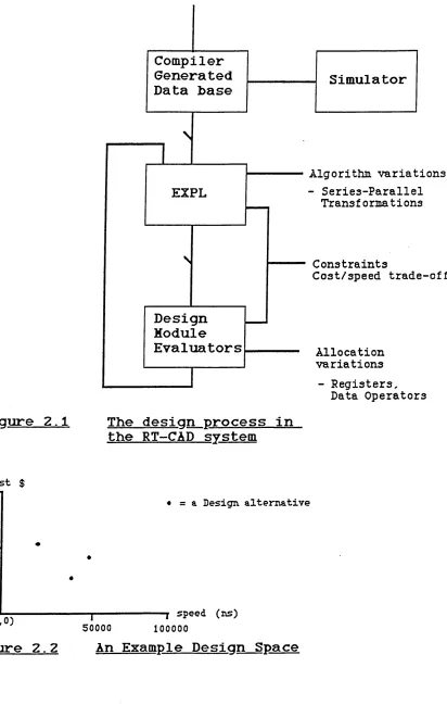
The system operates by accepting a behavioural description of the IC to be designed expressed in the ISP [2.7] hardware description language(HDL). This is then compiled and the object code produced is loaded into the system data base, where it can be manipulated by other design tools in the system. The structure of the system is shown in Figure 2.1.
The most important of these tools is EXPL[2.5]. It takes as input the object code from the ISP compiler, together with a set of user supplied cost and performance constraints. From the compiler output, EXPL generates a graph which represents the behaviour of the required system. It then attempts to manipulate the original graph to establish
alternative design possibilities. Essentially EXPL tries to determine which operations can be performed concurrently, and which must remain in a definite sequence. Each
alternative design is passed on to the module set
evaluators. These complete and evaluate the design for each alternative in terms of its hardware module set. The
ISP DESCRIPTION
Algorithm variations - Series-Parallel
Trans £ o rma t i ons
Constraints
Cost/speed trade-off
Allocation variations
- Registers,
Design
Module
Evaluators
EXPL
Compiler
Generated
Data base
Simulator
Data Operators
Figure 2.1
The design process in
the RT-CAD system
cost $ 1000 n
500 “
(
0,
0)
• = a Design alternative
[image:23.612.203.521.42.428.2]T--- T speed (ns) 50000 100000
[image:23.612.105.517.47.696.2]to discard as impractical, and which to keep in order to generate further solutions by yet another application of graph transformations. In this manner, the process is continued until EXPL finds the optimal implementation within the given constraints.
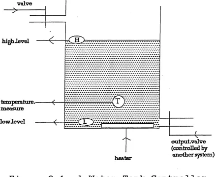
Thus, EXPL searches through the set of possible designs for a circuit. With the assistance of the technology-dependent module evaluators, it attempts to find the best solution which satisfies the problem specification. The set of
possible designs of a circuit is known as its design space. The design space, explored automatically by EXPL, can be depicted by a two dimensional graph, as in Figure 2.2. Each alternative design is represented on the graph by its cost and time co-ordinates. These are computed by the
technology-dependent module evaluators.
The exploration of the design space by EXPL is driven by the goals (cost and speed) set by the designer. Ideally the goal is to find an alternative design whose position in the design space is as close as possible to the origin (0 cost, 0 time). Realistically though, the least expensive
solutions are not the fastest, and vice versa. Therefore the aim of EXPL is to find a solution which has an
acceptable level of performance for minimum cost.
The RT-CAD system also includes design tools which perform the verification and simulation of ISP descriptions. It is possible to develop syntactically correct ISP descriptions which make no sense semantically. The system guards against this happening by checking the correctness of the semantics of each design specification. Simulation of ISP designs is performed by stepping through the flowchart which is
produced by the ISP compiler. An interactive command
2.1.3 ULYSSES
ULYSSES is a sophisticated VLSI CAD environment developed at CMU[2.8]. It aims to automate the design process, and consequently lower the design cost, of complex VLSI
components. Other CAD systems[2.9] require the designer to manually execute individual design tools, and to manage the various files used as input to CAD tools, or created as output by tools. In ULYSSES, all the required CAD tools are fully integrated and controlled by the system itself. Thus the designer interacts with the system at a higher level. ULYSSES completes a design by automatically invoking the required tools, and managing the various intermediate files produced by the individual tools. This allows the designer to concentrate on the high-level design, without needing to become an expert user of a complex CAD system.
In order to effectively address the problems of CAD tool integration, ULYSSES employs Artificial Intelligence(AI) techniques. It functions as an interactive expert system, interpreting design descriptions and initiating design tool executions. Specifically, ULYSSES has the ability
to:-1. manipulate a variety of hardware description languages
2. describe and automatically execute a diverse set of design tasks
3. allow the designer to arbitrarily interrupt, restart, or redirect a sequence of design tasks 4. represent important design decisions
5. explain its sequence of design activities and provide reasons for specific design decisions 6. maintain the design history for each significant
design point
7. evaluate competing design points during design elaboration
ULYSSES incorporates a sophisticated, knowledge-based scheduler to control the execution of the individual CAD tools. The knowledge associated with the scheduler enables ULYSSES to achieve much of the flexibility that it requires to successfully complete a design. The scheduler can be controlled by the designer, who may wish to interrupt a sequence of design tasks which are performing erroneously. In such cases the designer may choose which tools to
execute to continue with a particular design.
The need to control the vast volume of data generated as a circuit design is synthesised presents a significant
problem in ULYSSES. Each stage in the design process produces an intermediate description in some appropriate notation. Further, alternative implementations may be produced at each design stage. These arise when different trade-offs of design parameters, such as cost, speed and power consumption, are considered. Thus these alternatives represent competing design points in the design space of a circuit.
In ULYSSES, a frame-based[2.10] tree structure is employed to characterise the design space[2.11]. Each node in the tree represents a particular state in the evolution of a design. As CAD tools are used to add details to a design, child nodes are created which correspond to the new
situation. As several alternatives may be produced at each stage of the synthesis process, a node may have several children emanating from it, each of which corresponds to a different design decision. Relations link design points to their parents, so that a child node can inherit design information from its parent. This means that only new or altered data needs to be stored at a child design point. The use of a tree structure has the advantage that it is possible to backtrack to a parent design point when further progress from the current design cannot be made. Also, a terminal node in this design space will represent a
ULYSSES adopts the blackboard model of the Hearsay 2 system[2.12] as a model for its architecture. In ULYSSES, each CAD tool is viewed as a knowledge source. All
knowledge sources are considered to be self-activating, asynchronous parallel processes. Knowledge sources
communicate via a blackboard, which is effectively a global data base. The blackboard supports the many levels of
representation necessary in a circuit design, and in
particular, it holds the whole design space. Each knowledge source has a set of pre-conditions associated with it,
which must be satisfied by data in the design space before it can execute. Consequently, the knowledge sources
periodically monitor the evolution of the design space. When the pre-conditions of a knowledge source are met, that knowledge source is activated. A special knowledge source, the Rating Policy Module, is activated by the scheduler whenever the design space is altered. It provides a uniform basis for comparing alternative designs and for pruning unpromising designs from the design space.
Another important aspect of ULYSSES is the ability to describe a wide variety of design tasks and methodologies. This mechanism is provided by the Scripts language, which, while retaining all the facilities normally associated with a production system[2.21], also allows some tasks to be specified procedurally[2.13]. Essentially a script is a set of instructions which realise a given design task. Thus a script can be said to provide a method of composing a very large production rule out of a sequence of individual
knowledge source executions.
2.1.4 Synapse
Synapse[2.14] is an experimental expert system intended to support VLSI design. The goal of the system is to enable a very high level specification of a problem, including
design of a VLSI circuit in Synapse involves the repeated transformation of algebraic expressions until an expression is reached that represents a viable solution. This approach to VLSI design is novel, representing a significant
departure from most existing paradigms.
The input to Synapse is a behavioural specification of the desired circuit: this forms the initial expression. Any number of transformations may be applied to this
expression, and all result in either legitimate designs or intermediate design states. In general, transformations either change the dimension or the level of abstraction of an expression (usually increasing the amount of detail), or they improve the system's performance attributes. All
transformations are formally proved to leave the functional behaviour of the system unaltered. When an expression has the desired performance characteristics, and is in the proper dimension such as a mask description, it may be viewed as a possible solution.
For any given specification, several possible
implementations may be generated if all the applicable transformations are applied. These represent different design points in the design space for the circuit. Synapse therefore utilises strategies to focus the search of the design space into the most promising areas. Synapse also allows the designer to perform transformations on
expressions. In this case, the designer is primarily responsible for proving that the transformations are correct, and for ensuring consistency between
representations.
Synapse uses KEE[2.15], an expert system development tool, to implement the inference engine. KEE provides facilities to maintain consistency between alternative design
Synapse is part of a long-term research project to explore expert system issues in CAD. Its novel approach to the domain of VLSI design has shown that AI techniques can be used successfully to automate the design process. Further work on Synapse is concentrating on enriching the system*s knowledge base and increasing its learning capabilities.
2.1.5 MAPLE
MAPLE[2.16] is an expert system developed at the University of Reading. Its purpose is to automate the design of
hardware for dedicated microprocessor applications. It attempts to satisfy the hardware requirements of a system by choosing the most appropriate combination of
pre-designed boards from its knowledge base. MAPLE does not attempt to design new boards for applications. However, MAPLE*s designers intend to extend its capabilities to
enable the design of boards from individual components, and to provide limited assistance with software design.
MAPLE is implemented as an interactive system, and each * consultation' has three distinct stages: INTERVIEW, DESIGN and REPORT. The INTERVIEW stage enables MAPLE to acquire the design goals and constraints of the application. The user is requested to specify the hardware requirements and constraints such as power consumption and cost. During the DESIGN stage, MAPLE uses its knowledge to design a system to meet the applications requirements. Finally, during the REPORT stage, MAPLE issues a complete set of documentation for the design, and a list of any assumptions that were taken.
MAPLE is implemented in a procedural language (PASCAL). This means that the rules MAPLE applies during the design phase are embedded in the code of the search algorithm. Therefore, in order to add or modify rules, the algorithm itself must be altered. This is a considerably more
involves providing more data. Altering the design algorithm requires in depth knowledge of the program, and could
involve extensive testing to ensure that any changes have not introduced errors.
Although MAPLE's capabilities warrant classification as an expert system, its internal architecture does depart from the expert system paradigm of a separate knowledge base and inference engine. So, in many respects, MAPLE is similar in construction to many of the algorithmic-based CAD systems which exist[2.17]. In justification of their implementation strategy, MAPLE's creators claim that the problem of
microprocessor hardware design can be solved by a
well-defined, compact strategy, which is unlikely to change dramatically[2.18]. While this may be correct[2.19], a
procedural implementation will almost certainly complicate the task of extending MAPLE's abilities. The added
complexity of designing software as well as hardware for applications, and the creation of new boards from
individual components will require the adoption of a much more flexible approach. It is doubtful that a well-defined algorithm could be confidently developed to perform such a collection of integrated design tasks. Consequently, it is likely that the full utilisation of knowledge-based
techniques would allow a better solution to be reached.
2.1.6 XCON
XCON (originally known as Rl) was developed by a research team at Carnegie-Mellon University(CMU) [2.20]. Its domain of expertise is the configuration of VAX 11-780
minicomputer systems, and it has been used successfully by Digital Equipment Corporation (DEC) since 1982. VAX systems are not offered to customers in standard configurations. Rather a customer may order a specific configuration of input, output, storage, processor and software. XCON's task is to determine a correct configuration for an order. This involves recognising any interdependences between
output produced may be used directly by technicians to assemble the system.
XCON takes a set of components as input and produces diagrams showing the required physical relationships between the components. Although XCON cannot perform the task of selecting components to satisfy a functional specification, it is capable of determining which
components require others in order to be configured. If the component set given to XCON is incomplete, it adds
whichever subsidiary components are required (e.g. cables, cabinets).
XCON is implemented in OPS5[2.21], a general-purpose
rule-based language developed at CMU. 0PS5 provides a rule memory, a global working memory and an interpreter that tests the rules to determine which are satisfied by the data held in working memory. Rules in 0PS5 are expressed as IF-THEN statements. These consist of a set of conditions which can be matched against the descriptions in working memory, and a set of actions which modify the data in working memory. On each cycle, the interpreter selects a rule which is satisfied and applies its actions to the data in working memory. Actions always add to or modify working memory. Thus in XCON, the rules have conditions that
recognise situations in which an extension is required to an incomplete configuration; the actions then effect that extension.
In XCON, 0PS5's two memories are augmented by a third, This memory, the data base, contains descriptions of each of the components supported for VAX systems. Each data base entry comprises the name of a component and a number of
attribute/value pairs which describe the important
properties of the component for the configuration task. As XCON configures an order, it retrieves the relevant
Production, or rule memory contains all of XCON's knowledge of how to perform the configuration task. These rules can be viewed as state transition operators. The conditional part of each rule describes the properties that a state must possess in order for the rule to be applied. The action part of a rule specifies which features of the current state must be modified or augmented in order to reach a new state on the solution path. Each rule is a more or less autonomous piece of knowledge that waits for a
state it recognises to be generated. When this happens, it effects a state transition. The new state generated should subsequently be recognised by one or more other rules, which in turn effect a state transition. This process continues until the system is configured.
XCON differs from other domain-specific systems primarily in its use of Match[2.22] as opposed to Generate-and-test as its central problem-solving strategy [2.20]. Rather than exploring several hypotheses until an acceptable one is found, it exploits its knowledge of its domain to generate a single acceptable solution. With Match, the conditions associated with each state are sufficient to guarantee that if a state transition is permissible, then the new state will be on the solution path. Thus with Match, false paths are never followed, and so backtracking is never required. In the configuration task, the knowledge available at each step is normally sufficient to distinguish between
acceptable and unacceptable paths. There is only one subtask in XCON for which several alternatives must be generated before the optimum solution is found.
The significance of XCON is mainly due to the fact that it was the first knowledge-based CAD system to be used in the commercial world. It proved that expert systems could be used to automate design tasks, and provided a development methodology that should be applicable to other
the task of refining and extending the knowledge base [2.20].
2.1.7 Others
The vast range of expert system developments in CAD makes it impractical to cover each system in detail. However there are several important examples which are worthy of note. EL and SYN are two expert systems developed at the Massachusetts Institute of Technology. They are intended to help a designer analyse analogue circuits [2.24]. Palladio is a prototype expert system under development at Stanford University. The major goal of Palladio is to enable
designers to construct VLSI circuits, and at the same time explicitly express the design heuristics that were used. Designers may create personal knowledge bases which can be incorporated into circuit designs[2.25]. This capability should encourage experimentation with VLSI design
methodologies.
2.2 Software Specification Techniques
2.2.1 Introduction
The need for languages which provide precise specifications at all stages of the system development life-cycle is
widely recognised[2.26]. A considerable amount of research has been carried out in this area, but there are still no generally accepted tools or methodologies. A possible
reason for this lies in the fact that each stage of system development requires a specification at an appropriate
level of detail, expressed in a suitable notation. Further, different types of applications have unique
It is possible to identify three categories, which provide a meaningful framework for the investigation of the many existing languages[2.28]. These
are:-a) phase of applicability b) area of application c) language model
The following sections elaborate on these categories.
2.2.2 Phase of Applicability
Specification languages can be used to describe target software systems from the first phase of requirements definition up to the physical specification of program design. An initial requirements specification may be
abstract and vague. But as successively more information is added, the level of detail increases, and this continues until the development of the actual computer programs is complete. Within this development spectrum, three broad areas of specification languages can be defined[2.28].
2.2.2.1 Requirements Specification Languages
Requirements specification languages(RSLs) are used to describe the initial user requirements for a computerised system. RSLs describe the basic functions of the system, together with constraints such as structure and
performance. Thus RSLs provide a problem-oriented
description of systems, stating what needs to be done, not how. An early and wellknown example of an RSL is PSL -Problem Statement Language[2.29]. More recent examples include formal specification languages such as Z[2.30] and OBJ[2.31].
2.2.2.2 Design Specification Languages
At the next level of refinement, the requirements
carried out. The major functions of the system and their relationships are identified. Thus design specification languages(DSL) can be said to specify how a system can achieve its aims. It is a solution-oriented description of a software system. A typical representative of DSLs is D D N [2.32].
2.2.2.3 Program Design Languages
Once the overall design of the system has been finalised, algorithms and data structures have to be developed and precise interfaces between modules established. Program design languages (PDL) therefore provide facilities which are specifically related to data structure specification and module interaction, and are implementation-oriented. GYPSY[2.33] is an example of a PDL.
2.2.3 Area of Application
Software systems can be classified as being sequential, concurrent or real-time[2.34]. Sequential software systems can be specified as sequences of actions, always performed in the same order, with no two actions performed together. Concurrent systems consist of several activities occurring in parallel and communicating in some controlled manner. In real-time systems, activities may occur sequentially or concurrently. However real-time software must be capable of responding to external stimuli within a specified time
period, and further, the order in which stimuli arrive may not be predictable.
Real-time and concurrent systems tend to be considerably more complex than comparable sequential systems.
Consequently a specification language intended for sequential data processing systems would be totally inappropriate for specifying a complex real-time
Thus, the description of the relationships between external stimuli and responses is vital in real-time and concurrent systems, whereas file formats, data integrity and
validation criteria may be the most important aspects of a sequential data processing system specification.
2.2.4 Language Model
Three separate concepts can be identified which form the basis of existing specification languages [2.27]. These are described
below:-2.2.4.1 State-based Languages
State-based languages are based upon the model of finite state machines[2.35]. They provide a method of specifying the set of possible states of a system, and the state transition functions which enable the system to move from one state to another. The major advantage of state-based languages is their use of abstraction. It is possible to abstract the state space so that it reveals details only of particular interest. This can be done at each stage of the development process, allowing specifications to be
hierarchically structured. Examples of state-based languages are GYPSY[2.33] and DREAM[2.36],
2.2.4.2 Event-based Languages
2.2.4.3 Relational Languages
Relational languages allow systems to be described in terms of the required relationships between important properties of the desired system. These properties usually include the inputs to be processed, the outputs to be produced, the functions to be performed and the events that may occur. Relationships may then be created between inputs, functions and outputs. Two specification tools which have been built around the relational model are RSL[2.39] and PSL[2.29].
In general terms, it appears that state-based languages find their most natural application in design and
implementation specifications, whereas relational languages are best suited to requirements specification. However, it seems that event-based languages are not so easy to
classify, and may be useful at several levels of the development process[2.27].
2.2.5 Desirable Features of Software Specification Languages
Irrespective of their intended application, it is possible to define a set of common goals which a specification
language should meet[2.40].
a) Understandability b) Analysability c) Maintainability
These criteria have many implications on the facilities which a specification language should provide. A number of
the more desirable features are summarised
below:-2.2.5.1 Understandability
1) Dimension of language — Specification languages may be characterised as one-dimensional (character string
hybrid(written/graphical languages) [2.41]. Although
graphical languages seem to be superior in terms of overall clarity, problems exist because of their limited
'processability'. However recent advances such as
compilable graphics have to some extent alleviated these problems[2.42].
2) Level of detail — It is important that a specification only contains information that is relevant to the current phase of development. A language should facilitate the suppression of irrelevant details, enabling the overall structure of the specification to be easily visible. In this way, specifications can be developed incrementally from a vague statement of requirements to a complete physical design. Good examples of languages which employ this approach are PDL[2.43] and SPECLE[2.44].
A commonly used abstraction mechanism which allows the hiding of unimportant data is modularisation.
Specifications can be decomposed into small meaningful units which are defined at a lower level of detail. A
specific modularisation technique known as data hiding has been included in many implementations[2.45]
3) Formality — Formal specifications of systems eliminate all sources of imprecision by using precise syntactic and semantic definitions. Unfortunately specifications written in formal notations are difficult to comprehend. In
contrast, informal specifications incorporate abstraction techniques to focus on important issues and increase
understandability. This fact makes informal notation
difficult to analyse and verify. Obviously then, a proper balance must be sought between formal and informal
2. 2. 5 . 2 Analysability
1) Static validity — It should be possible to analyse a specification and check for such properties as conflict, ambiguity and redundancy. This is analogous to syntax checking in conventional languages.
2) Traceability — This refers to the capability of verifying a specification against its successor or predecessor. As already stated more than one level of specification will generally be needed during the
development of a system. It is therefore important that each level of specification is functionally equivalent, and that no errors or inconsistencies are introduced.
3) Dynamic validity — This objective is concerned with the evaluation of the behaviour of specifications before
implementation proceeds. Specifications should be
executable, forming a simulation of the required system. In this manner, a specification may be modified until its
behaviour is deemed satisfactory. This facility is of particular importance in the realm of real-time systems, where performance and efficiency are of particular
interest, and is demonstrated by the SREM project[2.39].
2.2.5.3 Maintainability
1) Modification — Languages should allow specifications to be easily extended or adapted. Useful facilities which simplify updates to software include data hiding and
modularisation[2.45]
produce updated documentation when the specification is altered.
2.2.6 Examples
2.2.6 .1 Vienna Development Method (VDM)
VDM is a formal specification language[2.48]. A VDM specification defines a system in an
implementation-independent manner. This is achieved by using mathematical models to describe objects and
structures, as well as the meaningful operations which may be performed upon them. In VDM, the mathematical models of structures are abstract data types, described using the ideas of sets, functions and relations. Operations allowed upon structures are also specified using such mathematical notations. A VDM specification has three distinct
components: a state definition, the definition of invariants, and the definition of operations.
The state definition describes the structures required in terms of basic types (real, integer, Boolean), which can be combined using special constructors to give the
mathematical notions of sets, sequences and functions. Composite types can also be formed from these basic types. The individual elements of a composite type do not need to be of the same basic type; composite types may in fact be defined recursively.
Invariants are constraints which must be preserved by operations. Invariants thus represent properties of the system which must always hold true. In VDM, invariants should be proved for each operation.
operation produces valid results. The post-conditions defines the effect of performing the operation.
VDM specifications are unambiguous and free of design and implementation directives. They are also not directly executable. The execution of formal specifications is a desirable feature of a specification language.
Specification execution provides a prototype implementation of the desired system. This can be used to remove syntactic errors, and increase confidence in the correctness of the specification. In order to execute VDM specifications, the structure definitions must be reified and decomposed into code for a programming language. Reification consists of moving from abstract data types to the sorts of data
structures available in a target programming language. For example, a VDM sequence may be represented as a linked list or an array in most common programming languages. Further, the operations specified for the original abstract data types must be respecified to operate on the reified, more realistic data types, and the abstract operations must be decomposed into statements in the target language. Still, this is not sufficient to guarantee that the implementation inherits all the desired properties of the specification. Consequently, proof obligations must be provided, to show that the implementation is indeed correct with respect to its specification.
Clearly, the process of reification, decomposition and proof of correctness is extremely complex, and may not be generally feasible or applicable[2.49]. Certainly a
comprehensive set of development tools such as
2
.
2.
6.2 EspresoEspreso is a language for specifying the requirements of complex, real-time process-control systems[2.50]. A
fundamental assumption of the language design is that system requirements have an inherent hierarchical structure, which should be detected and encoded in a specification. Espreso thus allows specifications to be built hierarchically by providing extensive module
packaging and data hiding facilities.
Logical and arithmetical expressions are not permitted in Espreso specifications. Rather, the language constructs are limited so that only the high-level aspects of the problem may be addressed. This has the effect of reducing the
number of concepts in the language, and of preventing the user from dealing with low-level details and algorithms too early. The language does however facilitate the expression of parallel operations at an abstract level, and includes well-understood mechanisms for controlling message passing and access to shared resources. It also allows informal, text descriptions to be entered. Although these cannot be analysed, they do provide a convenient method for the user to express ideas which are not fully formulated.
The Espreso language is formally defined by an extended attribute grammar, which describes the complete language syntax[2.51]. The provision of a formal language definition helps guard against unforeseen inconsistencies and
ambiguities in the language, and makes specifications more amenable to checking and verification. Each Espreso
construct is expressed in a Pascal-type manner. This has the consequence that Espreso specifications resemble skeleton Pascal programs. By refining the specification, manually or partially automatically, a prototype
implementation of the specification can be produced.
features which are appropriate to its intended level of detail and application area. Although Espreso
specifications are not executable, many aspects of static validity can be checked for, and the specification forms a reliable high-level source for further refinement of
detail.
2.3 Hardware Description Languages
2.3.1 Introduction
A hardware description language(HDL) is a notation which may be used to depict particular aspects of digital
systems[2.52]. The complexity of digital systems design has led to the development of many HDLs. The aim of HDLs is to conquer complexity by the systematic use of abstraction at each level of the design process [2.52]. There are many levels in the process of hardware design, ranging from circuit and logic design to behaviour and system
specification. Each level has its own purpose, and each level needs to be described. Therefore different HDLs reflect different levels of abstraction of computer hardware[2.53]. In general terms though, HDLs may be
classified as providing either physical information on the structure and interconnection of components, or
behavioural information on the function of circuits[2.54]. Many languages attempt to provide both structural and
behavioural descriptions. However these two aspects of hardware are best described by different notations.
Consequently, languages which incorporate facilities for both types of descriptions usually include two distinct types of notation[2.55].
2.3.2 Structural HDLs
Many situations arise during hardware design where there is a need to describe the structure of a circuit without