Chip breaking performance of cutting tools with unusual
forms.
WALTON, Ann B.
Available from Sheffield Hallam University Research Archive (SHURA) at:
http://shura.shu.ac.uk/20493/
This document is the author deposited version. You are advised to consult the
publisher's version if you wish to cite from it.
Published version
WALTON, Ann B. (1984). Chip breaking performance of cutting tools with unusual
forms. Masters, Sheffield Hallam University (United Kingdom)..
Copyright and re-use policy
See
http://shura.shu.ac.uk/information.html
Sheffield Hallam University Research Archive
TELEPEN 100217576 3
0
Z - ( o {
Sheffield City Polytechnic Library
ProQuest Number: 10701140
All rights reserved INFORMATION TO ALL USERS
The quality of this reproduction is dependent upon the quality of the copy submitted. In the unlikely event that the author did not send a com plete manuscript and there are missing pages, these will be noted. Also, if material had to be removed,
a note will indicate the deletion.
uest
ProQuest 10701140
Published by ProQuest LLC(2017). Copyright of the Dissertation is held by the Author.
All rights reserved.
This work is protected against unauthorized copying under Title 17, United States C ode Microform Edition © ProQuest LLC.
ProQuest LLC.
789 East Eisenhower Parkway P.O. Box 1346
"Chip Breaking Performance of Gutting Tools With Unusual Forms.1'
ANN B. WALTON B.Sc.
A thesis submitted to the CNAA as part of the requirement for the degree of Master of Philosophy.
Sheffield City Polytechnic
^ .j,..
"
t hABSTRACT
Chip Breaking Performance of Cutting Tools with Unusual Forms."
A. B * Walton.
This work shows one solution of the problem of predicting
the chip breaking performance of a groove-type chip
breaking device. The relationships between the dimensions
of a simple grooved tool and the range of undeformed chip
thickness which gives acceptable chip breaking are re
examined by conducting cutting tests on laboratory prepared
tools. These experiments enable the repeatability of data
to be assessed. The range of workpiece materials is also
extended.
A nomogram is devised, using the results of these tests,
to predict the range of undeformed chip thickness over which
chips are broken satisfactorily from a 1mowledge of the tool
dimensions. The nomogram meets one need specified in a
survey of tool users in the Sheffield area which is for a
simple, scientific method of fitting a chip breaker to
cutting conditions. It is recognised that computers have a
part to play in developing the nomogram principle and that
the scope of the nomogram could be greatly increased using
this medium.
In response to another requirement of tool users in industry
the project is widened to consider the behaviour of some
recently produced commercial tools. The aim of this
investigation is to comment on the effect each profile
has on the chip breaking performance of the tool. It is
necessary to separate and classify features on the tools
since the profiles are in some cases very complex and not
easy to analyse. Assessment is made of how readily the
CHAPTER 1 An Introduction,
CHAPTER 2 A critical appraisal of previous work on Groove type “Chip Breakers,
2.1 Chip formation and modes of Chip breaking.
2.2 Relationships between the configuration of
the simple groove type chip former, the workpiece material and the chip breaking performance of the tool.
2.3 The influence of Fundamental Parameters.
2.3.1 Groove width.
2.3.2 Land Length and Land Angle. 2 .3.3 Workpiece Material.
CHAPTER 3 A description of Experimental Equipment and Procedure.
CHAPTER If. Experimental work on the Simple Grooved Tool.
U.1 The relationship between Chip radius, Groove
width, Land Length and Workpiece material. i-j-,2 The chip fracture strain and size ratio
relationship.
k»3 The land length and land angle relationship,
4.U Discussion of results of tests on the simple grooved tool.
1|.3 Inconsistency of results.
CHAPTER 5 The chip breaking Nomogram.
3.1 Introduction.
3.2 The Nomogram to predict Chip breaking
performance of a tool.
3.3 Application of Computers.
CHAPTER 6 The investigation into the performance of Tools with unconventional profiles and their significance.
6.1 An introduction to recently produced tool
profiles.
6.3 The influence of Shallow Grooves inlet angle on Chip breaking performance. 6 .U The "Moat" effect.
6.5 The influence of Multiple Grooves on chip
breaking performance.
6.6 The influence of.change in chip cross section on chip breaking performance, 6.7 The influence of “Dimples’1 or protrusions
on the chip breaking performance.
CHAPTER 7 Conclusions.
APPENDIX A List of firms visited.
APPENDIX B An example of the use of the Nomogram.
APPENDIX C Example of computer program based on Nomogram and a sample problem.
TABLES
FIGURES
LIST OF TABLES
1. Workpiece constant.
2. Dimensions of four simple grooved tools.
3c Chip radius versus Undeformed Chip Thickness for four Simple Grooved tools.
I4. Workpiece constant for five workpieces.
3 . Chip fracture strain from onset of acceptable Chip breaking.
6 . Hg versus Land Angle.
7 . Comparison of Chip breaking ranges by experiment and from the Nomogram.
8 . Comparison of Straight and Tapered Groove tools. 9. Comparison of actual and calculated Chip radius for
"Cintride" tool.
10. Summary of operation of ’'Dimple'* tools.
11. Comparison of Actual and Calculated tool dimensions for "Dimple" tool.
12. Summary of operation of Sumitomo "Spiky-S" tool. 13. Summary of Operation of Sumitomo "Bumpy-G" tool.
NOMENCLATURE
A R 1 - R
*1
CC = Chip tool contact length,
LL = Land Length.
R = Radius of "broken chip.
R^ = Radius.of expanded chip at fracture.
W = Groove width.
W e^» = Effective groove width.
h = Undeformed chip thickness.
h^ = Undeformed chip thickness at onset of
acceptable chip breaking.
hg = Undeformed chip thickness wheii chip begins
to use the groove.
h/£ = Size ratio.
(h/^)crit = size ratio at commencement of acceptable
breaking.
n = material constant.
^ = Built-up edge angle.
(W x = Maximum built-up edge angle,
y = ... Land angle,
£ = Chip fracture strain.
There has recently been a proliferation of new designs of chip breaking devices and a need has arisen to
provide an independent basis for the assessment of
5
the performance of these tools. The manufacturer s information, whilst accurate and sometimes extensive, does not help the tool user to compare one tool with another, nor does it lead him to a better design if the tool in question does not quite su.it his job. The problem dealt with here is one of providing a unified
approach to assessing the chip breaking performance of a diverse range of devices.
Firstly, it is necessary to have a new look at the relationships between the simple-grooved tool and its chip breaking performance with the intention of
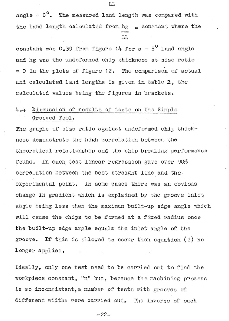
re-stating the expressions_in such a way as to provide a less theoretical guide to tool specification for the use of tool users in industry. The simple grooved tool referred to is one with a single, deep and curved groove which runs parallel to the cutting edge leaving a short land (figure 1). The theory to predict the
chip breaking performance of this tool with reference to groove width, land length and land angle and the
workpiece material has been presented previously by Worthington et al (1,2). This work is extended here
A survey was undertaken to discover what inform at 1021 the industrial users most required concerning
chip-breaking problems. The findings were somewhat discouraging since, although many problems were readily acknowledged, very little thought had been given to their solution. Three main problem areas were identified:
a) Tool users and some small manufacturers are not aware of the basic principles of chip breaking dnd therefore they rely on trial and error methods when selecting or designing chip breaking devices,
b) Problems are more acute when machining some special steels.
c) The facilities which are available in modern tool designs are not being exploited to the best advantage.
The list of firms visited is given in Appendix A.
A number of times during this survey discussions took place with the craftsman -who knew by experience
'exactly where to grind the chip breaking groove for ■ each particular ~]ob and the production manager-
admitted that there was nothing to replace this key worker. It is perhaps because the Sheffield area has been fortunate in having excellent craftsmen in its manufacturing industry that there is nowr such a lack of documented information within these firms,.
-2-As automatic production lines have taken over and tungsten carbide and ceramic tools are being more widely used the problems of controlling swarf have become more serious since cutting speeds are much faster and down time is more expensive. The main work of the firms visited is automatic or semi-automatic and most firms had volumes
5
of manufacturers data on the wide range of sophisticated tools now available, but this information was largely of a commercial nature and was non-scientific. Advancements in sintering and coating technologies have enabled
highly complex forms to be produced, for example curved cutting edges, protrusions on the tool face and multiple chip breaking grooves. Whilst these new designs may be improvements they have unfortunately added to the general confusion among cutting tool users. The approach by
industry to finding the optimum tool for a particular operation is to conduct trials on a range of tools and to select tine one which gives the best performance.
This is an expensive approach, partly because considerable time is involved and partly because little is learned to help with a similar problem later, also it does not
necessarily lead to the optimum too.l configuration.
The second part of the project is concerned with
providing some guidance when using these more complex chip breaking devices. The behaviour of a number of commercial tools is investigated. The contours which feature on these tools can be classified to a certain extent, for example, curved cutting edge, shallow groove and multiple groove are all features which can be
identified on the range of tools examined. The
assessment of the commercial tools and the subsequent guidelines are based on these features in the hope that this will facilitate the analysis of all tool configura tions.
The report gives details of tests performed on the
simple grooved tool and on a selection of commercial tool A nomogram to determine the chip breaking performance of
CHAPTER 2
A CRITICAL APPRAISAL OF
2.1 Chin Formation and Modes of Chip Breaking 2.1.1 Chip Classification
In the discussion- of chip control it is useful to have a method of classifying the size and shape of swarf which is produced hy the machining operation. The chip
classification system devised by Henriksen (3) is
probably the most comprehensive and widely known system. Henriksen describes as "good" those chips with full or almost full turns and the system included a range of "ideal" and ’’acceptable" chips. Henriksen, Takeyama(U) and others found that acceptable chips are produced when the ratio of the radius of the expanded chip at breaking to the original chip radius is between 1.2 and 2.0
(assuming most of the expansion is elastic and the chip fractures at a point above the cutting edge, half way
round, it collapses to produce a full turn chip / when to-W©- 2..^
9
Henriksen s classification is shown in figure 2.
Another important indicator of chip type and
acceptability is the "size ratio" which is the ratio of the undeformed chip thickness to the radius of the broken -chip. It is useful to note that the size ratio when
chip breaking is acceptable is in the range of 2 to 6 times the fracture strain of the chip (2). Typically, therefore cutting a metal with chip fracture strain of
There is. remarkably little difference in the fracture strain of chips from different materials, even when the mechanical properties of the parent metal is very
different (U)» This simplifies the problem of transferring chip breaking information about a particular tool
configuration from one workpiece material to another.
2.1.2 Chip Breaking Mechanism
The chip breaking mechanism has been described by a number of researchers, most notably Henriksen (l), Takeyama and Nakeyama (5). (The chip breaker
considered was usually an obstruction type but the same principle can be applied to groove-type chip breakers since once the chip has formed the breaking modes are identical). Pour modes of chip breaking were described by Nakeyama (5), the most useful being that where the
chip flows into the groove, is deflected by the groove heel to be curled (figure 3a) usually in a helix. The free end of the chip may then impinge on the tool flank (figure 3b) where it anchors and subsequent chip formation causes the chip radius to expand and eventually to break, usually at the point "A" where bending moment is
greatest (figure 3c). This mode of chip breaking gives chips which are cool and controllable and is therefore highly suitable for industrial machining processes.
Another common mode of breaking is where the free end of the chip strikes the workpiece shoulder and subsequent chip formation causes the chip radius to expand and
break often giving shorter chips than the previous mode
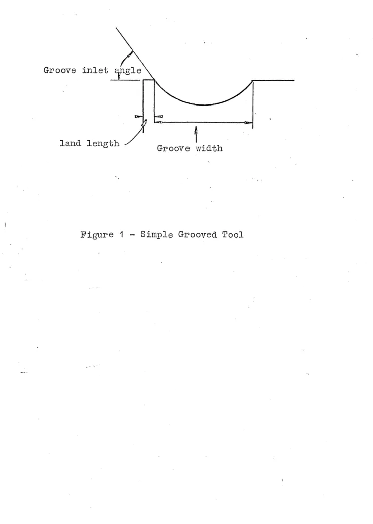
-6-and chips which may not he fully separated from each other, or alternatively the chip may he pushed downwards to form a coil, figure U* Both these modes, described independently by Nakeyama (5) and Spaans (6 ) give rise to high, intermittant cutting forces and are therefore undesirable. If there is some sideways curl the chip
is more likely to miss the workpiece shoulder and strike the underside of the tool. Once the chip has made
contact with the tool flank it has two alternatives, either to anchor and break in the mode described previously (figure 3 ) or it may slip and a helixical
chip will form which may break under its own weight after a short time, or it could form infinitely long helices which must be broken manually.
2,1.3 Controlled Contact Length Cutting
In order to understand the action of chip breaking devices on some, more complex tools it is necessary to consider more fully the conditions at the chip-tool interface. When metal is cut with a plain rake face tool there is a layer of stagnant workpiece material at the tool rake face known as the "built-up layer", some times this layer becomes work hardened and a number of layers build up to form a substantial structure known as the "built-up edge". This built-up edge, which may break away and re-form intermittently, has been claimed by
contact length" tool as described by Usui (7)*
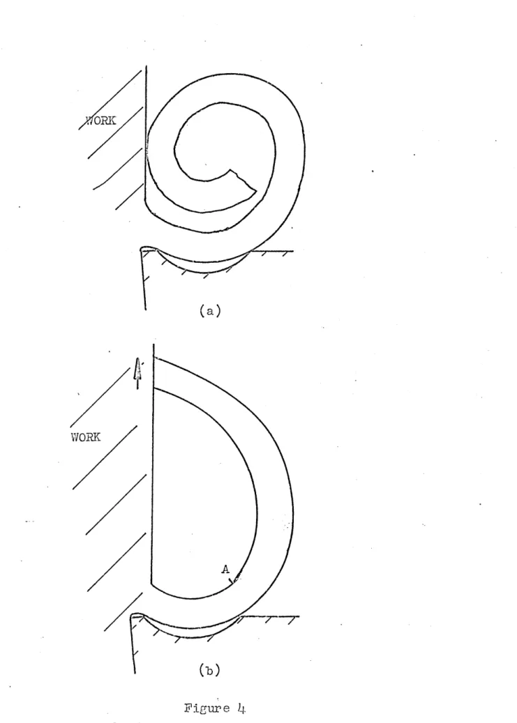
When metal is cut and continuous chips are formed with no built-up edge, the friction conditions are such that the chip apparently adheres to the tool for some
distance from the cutting edge, figure 5* Close examination of the zone of chip-tool contact reveals two regions: the region close to the cutting edge where •the real and apparent areas of contact are almost
identical- and the region further from the cutting edge where contact is between asperities only. These are respectively known as the regions of sticking friction and sliding friction. The contact length can be
artificially controlled by relieving the tool in the area of chip-tool contact, and an improved tool life may be realised by the reduction of friction and temperature at the 'tool tip. When cutting with restricted contact
length tools Usui (7 ) showed that a special plastic «
field exists on the land and is very much like a built- up edge in appearance. The special built-up edge
The groove type chip former has a short land and can \
"behave as a controlled contact length tool, with the
special "built-up edge forming on the land, Worthington( 1 ) investigated this further 'and found that when the
undeformed chip thickness is such as to allow the length of the sticking friction zone to equal the land length of the tool, the chip will "be formed straight, streaming at an angle equal to the special "built-up edge angle,.
2.1 cb Q-peration of Groove type Chip Formers Worthington was then able to propose a method of
operation for groove type chip formers. The chip streams into the groove and the free end is deflected upwards as it impinges on the groove contour. The free end of the chip then leaves the groove and the chip is formed across the groove making no contact with the groove profile. The radius of the chip is determined "by the "built-up edge
angle and the width.of the groove, figure (7 ).
The chip is plastically deformed at this radius and'can "be "broken in the ways suggested "by kakeyama (5 )* -tie formed radius, R of the chip can he determined from the -geometry (figure 3) as the groove width, W is divided "by
twice the angle of the special built-up edge, f!>
or:-R = w - ( 0
2 sin p*
There will he some elastic recovery of the chip as it leaves the groove, hut since the chip deformation is mostly plastic the change in radius is negligible. Also, when the end of the chip encounters the tool flank the
-9-subsequent expansion in chip radius is mostly elastic. In experimental work it is assumed that measurement of the broken chips gives an accurate value for the formed radius of the chip. According to Zorev s (8 ) theory concerning the built-up edge angle, the special built-up edge will never exceed forty five degrees and therefore, unless stated otherwise, the groove inlet angle is made
equal or greater than forty five degrees to ensure the groove profile never interferes with the chip (in many cases the maximum built-up edge angle is thirty degrees).
2.2 Relationships between the configuration of the simple groove type Chin Former, the workpiece material and the Chip breaking performance
of the tool.
Work by Worthington et al (1,2) has led to a number of expressions which comprehensively describe the relation ship between chip curl radius, undeformed chip thickness and tool geometry. The relationship between undeformed chip thickness and size ratio has been shown to be linear (1 ) with a gradient dependant on the workpiece material and the groove width:- ■
-1 n ( )
- 1 - hg _______ „
R W ( __ ) ^
h
where: n = constant for the particular workpiece, h = undeformed chip thickness.
At values of undeformed chip thickness less than hg the chip is assumed to he unaffected by the groove and either streaming or curling naturally.
Once the undeformed chip thickness is sufficient to allow the chip to enter the groove the chip radius decreases with an increasing built-up edge angle and the
relationship (2 )' is true providing the groove profile does not interfere with the chip flow. Prom equation (l) we can find the minimum chip radius
R min = W
2 Sin /3' max
Where P m ax is the maximum hui It -up edge angle (which
O ON
is never greater than 1+5 and is more usually ahout 30 ).
Other experimental results (1) show that the chip will begin to "use" the groove at a value of underformed chip
thickness, hg which gives the length of the sticking
friction zone equal to the land length of the tool. This ' value of the undeformed chip thickness, hg is influenced hy the configuration of the land and hy the workpiece material. It can he shown (l) that the size ratio, h/R
is related to chip fracture
strain:-t
= h A ________ 3R
where L = fracture strain of chip R = formed radius of the chip A = Ri - R
Ri
Applying the values, of
■breaking i.e., "between 1,2 and 2,0 then A is between 0*166 and 0*5 when breaking is acceptable* Suitable rearrangement of equation (3 ) and substitution for A give the range of breaking in terms of fracture strain*
= 2 § at the commencement of acceptable breaking.
( R ) crit ( n )
‘where hi = undeformed chip thickness at commencement of acceptable breaking,
( h/R )' crit = size ratio when acceptable breaking commences.
6 £ when "overbreaking" commonc
It is useful to re-arrange in terms of undeformed chip thickness, by Sobsh'k'k
and ha = 3 ( h ) ( W ) + hg ( R ) crit ( n )
vhere ha = undeformed chip thickness at the commencement of overbreaking
2.3 The Influence of Fundamental Parameters 2.3*1 Or o ov e w idth
The relationship between groove width and the chip breaking performance is given by a rearranged form of
h = h.W + h
g ___________(it)
R.n
which is shown graphically in figure 8 for a number of the groove widths.
A number of effects can be noted as the groove width is
increased:-(a) The range of feeds for acceptable chip breaking increases. The slope of the h/R v.h. graph is
equal ton/Wbut since n is constant for a particular workpiece it is the groove width which determines the slope of the graph and hence the chip breaking range.
(b) The lowest feed for acceptable chip breaking is higher.
(c) Prom, R = W/2 sin f> the chip radius at a particular feed is larger as groove width is increased.
The effective width of a groove will be changed by changes in. the direction of the chip flow. If the chip flow
direction is / 0 to the cutting edge then the groove width will be effectively increased by a factor of
i/cos 0° • The chip flow direction is influenced by the nose radius and chip width and by the inclination angle
The direction of the chip is particularly important when there is a groove in each face of the tool - as is described later.
2.3*2 Land Length and Land Angle
The configuration of the land is an important factor in that it determines when the chip begins to "use" the groove. On a plot of size ratio against undeformed chip thickness (figure 8 ) the undeformed chip thickness, hg, which causes chip streaming and, therefore, causes the chip to begin to use the groove is found where size ratio equals zero.
The radius of the formed chip increases with increase in land length for a particular undeformed chip thickness. The greater the land length, the greater the value of undeformed chip thickness for chip streaming and the undeformed chip thickness at which acceptable breaking commences.
The relationship betv/een land length and hg value is shown in figure 9. The gradient of the graph is dependant on the land angle, typically when the land angle is 90° then LL = 0.1+ hg
2.3*3 Workpiece Material
The influence of the workpiece material on the chip breaking performance of a tool is represented by the factor "n" in the
relationship:-h = k • ™ + relationship:-hg (1+)
R n
The value of "n" is found to be very similar for a selection of plain carbon steels, as seen in table 1, and only varies significantly with major changes in the properties of the workpiece* The variation in the
mechanical properties of the swarf from different materials was found by Takeyama (i0) to be very much less than the variation between the properties of the parent metals* Takeyama (10) gives some results for a shallow groove-type chip former and concludes that the higher the carbon content of the parent metal the more difficult the chip breaking is, but the evidence he provides is scant. In Worthingtons relationship (equation 4) the experimental results show the gradient of a size ratio (h/R) against undeformed chip thickness (h) to be dependant on the
material constant, but in practical terms only when a steel with a nn M~value of 1.5 is compared with a steel with
,,n ,,-value of say, 2,0 is any significant difference in
the chip breaking range observed. An example of the effect is shown in figure 8 which is drawn'..for an ,tn ,,-value of 1.5* The accepted values of the limits of acceptable chip breaking are set on the size ratio (h/R) against undeformed
chip thickness graph at h. = 0.06 and h = 0.18, which
R R
-15-The maximum and minimum chip thickness values for acceptable chip breaking can be read from the x-axis where the groove width line crosses these limits. From figure 8, the range of undeformed chip thickness would be from 0.22mm to O.i-pmm, for a 3mm groove and nn “ = 1 .5.
The same exercise for a high speed steel with an "n - value'' of 2.0 v/ould give acceptable chip breaking from 0.19mm to 0.37mmy undeformed chip thickness. It can be seen that the undeformed chip thickness for the onset of acceptable breaking has not changed significantly but overbreaking
commences at a lower undeformed chip thickness for the high speed steel which may well be noticeable.
-CHAPTER 3
The tools were prepared from plain, P30 cemented carbide inserts. The circular groove profiles were produced by-spark erosion, Using "elkonite” (a sintered bronze) bars as the electrodes, figure 10. The land angle was ground using a purpose made jig and an 8 inch, off-hand grinding wheel# All dimensions were measured using a Nikon tool makers microscope.
The material used for most tests was EN8, but tests using M2, EN9, EN19b were performed to quantify the differences in values of the material constant. A section of the EN8 bar was examined to check the homogenity; no significant
defects or variations were found. Cutting fluid was not used in any test since this would add inconsistencies in that control of the flow of fluid could not be guaranteed for each test.
An infinitely variable speed lathe was used for the tests, which enabled the cutting speed to be kept constant (at
120/min for most tests). The cutting speed was checked using a surface tachometer. The range of feed rate was between 0.1mm/rev and 1 .Omm/rev - the uc.t. can be regarded as nominally the same as the feed since the tool cutting edge angle was 13° in most cases i.e., a difference of about 3%»
In each test the chips produced were collected and the
outside radius of the chips was -measured using radius gauges micrometers or rule, as appropriate for the size of the chip Several chips from each test were measured and the average radius was found.
Variations to the basic groove shape were required for some tests. A tapered groove was produced using an elkonite rod which had been taper turned and was carefully aligned to ensure that the land was formed parallel to the cutting edge In testing the effect of a "dimple" the "dimple" was
produced by spherically forming the end of an elkonite rod and using it to spark erode the P30 insert close to the corner. For the tests comparing the effect of rough and smooth tool flanks, the roughness was provided using a knurled piece of brass as the electrode to spark erode the
inverse shape of the knurl onto the tool, two patterns were used, a diamond knurl which gave a dotted flank and a knurl giving a series of grooves parallel to the cutting edge. In order to examine the deformation at the chip-tool
interface, quickly stopped samples were obtained using the device shown in figure 11.
The device consists' of a humane killer gun with a captive bolt, mounted above a tool holder, pivoted slightly beloW centre height aiid supported by a pin. The screws preload the tool holder to preveiit it from moving. Cartridges were used to fire the device. The gun is fired whilst
toolholder, the supporting pin shears-and the toolholder accelerates from the workpiece. Plasticine under the tool cushions the fall, preventing rehound and damage to the toolholder. The shear pins are made of silver steel and are notched to facilitate quick fracture. The device is mounted in place of the tool post on the cross slide of the lathe.
The difficulties of removing the sample from the bar were overcome by machining a mild steel tube and parting off
the section holding the sample. It was then a simple matter to saw around the sample to obtain a specimen suitably
sized to be mounted.
The samples were cleaned of dust and mounted in clear pers pex. The mounts were ground to reach the section to be examined and then polished and etched.
Always at least three, and usually more, quick stop samples were taken for each analysis required, to ensure the
section examined was representative.
CHAPTER U
il.1 The relationship between Chip Radius, Groove Width, Land length and Workpiece material.
A number of tools were prepared in the Laboratory with various dimensions - details of four of these tools are given in table 2. Each of these tools was used in tests cutting EN8 steel and noting the chip type and radius over a range of feeds. The object of the tests was to verify the relationships described previously (equation U) for the particular workpiece and to examine the repeatability
of the chip breaking performance. The feed was accepted as the value of undeformed chip thickness and the average
radius of a number of chips formed at each feed setting was found. The results of the four tools are given in table 3 and are plotted in figure 12. The best straight line was •found by linear regression, giving a value for the gradient
and the interception with the feed axis. The workpiece constant can be determined from the gradient and the tool groove width, and since the same workpiece was used through
out the changes in gradient on figure 12 should be due to groove width only. The dimensions in brackets in table 2 are those calculated from the graph of figure 12 for each tool.
The interception gives the undeformed chip thickness (feed) at which the chip began to use the groove and since there is a fixed relationship between land length and this
The inverse of the gradient for each tool was taken and plotted against the tool groove width to give a new plot figure 13 with a gradient equal to the material constant, n for the workpiece. The results for -five workpieces are given in table 4#
4.2 The Chip Fracture Strain and Size Ratio Relationship, The fracture strain, £ for the chip has been shown to be related to the size ratio when chip breaking just becomes acceptable (equation (3) )• Tests were carried out to estimate the fracture strain for a 0,45% carbon steel by recording the undeformed chip thickness and chip radius at v/hich single full turn chips were produced with a number of tools. These results are given in table 3 and the average fracture strain is calculated to be 2,2%, which can be
compared to the values for similar steel, found by Spaans(6), Nakeyama (5) and Takeyama (10) v/hich were 0.7% to 1.3%*
0.4% to 1.49% and 4.3% to 3.3%> respectively. A similar exercise for the size ratio and undeformed chip thickness when overbreaking commences (indicated by chips of half turn
or less) yields a fracture strain of 3.5%.
4.3. The Land length and Land Angle Relationship.
The ratio of the undeformed chip thickness at which the chip uses the groove to land length: hg is shown to be
LL
Figure 14. gave a value of hg = 0,378 at land
LL
angle = 0°, The measured land length was compared with the land length calculated from hg = constant v/here the
LL
constant was 0.39 from figure 14 for a - 5° land angle and hg was the undeformed chip thickness at size ratio = 0 in the plots of figure 12. The comparison of actual and calculated land lengths is given in table 2., the calculated values being the figures in brackets,
4.4 Discussion of results of tests on the Simple Grooved Tool.
The graphs of size ratio against undeformed chip thick ness demonstrate the high correlation between the
theoretical relationship and the chip breaking performance found. In each test linear regression gave over 90%
correlation between the best straight line and the
experimental point. In some cases there was an obvious change in gradient which is explained by the groove inlet angle being less than the maximum built-up edge angle which will cause the chips to.be formed at a fixed radius once the built-up edge angle equals the inlet angle of the groove. If this is allowed to occur then equation (2) no longer applies.
Ideally, only one test need to be carried out to find the workpiece constant, "n" but, because the machining process is so inconsistent,a number of tests with grooves of
different widths were carried cut. The inverse of each
-22-gradient of the h/R graphs from these tests was plotted against the groove width of the corresponding tool and the slope of the best straight line through these points and the origin gives the ,,n 1,-value. There was always some scatter about this experimental line, for example, the tests to give "n" for EN8 (table 4) had a standard devia tion of 0,19 and mean of 1.43*- The variation in n-value for any one material can be as high as 14% and this is
to be compared with the variation in the average nn M-values for the different materials tested which is of the same
order. Since the un n-value is so inprecise it is not appropriate to differentiate between any of the materials examined for chip breaking purposes. Prom the range of workpieces tested it is reasonable to group all plain carbon steels together with an ,,n n-value of say 1.5*
Further grouping can be envisaged allocating an "n" value, which is equally suitable for all steels within the group. Many chip breaking problems have been encountered by users machining "special" steels e.g., stainless and aircraft metals and it would be useful for such users to be able to relate the 1,n ,,-value to a property or properties of the parent metal. A list was drawn up of a number of commonly available parameters for the properties of the steels
be the case that if relationships are found the practical difficulties will still exist because the
properties of any one steel will vary due to the company and method of manufacture and the heat treatment it has received. In this investigation a steel with greatly different properties from the plain carbons was examined to find the material-constant. EN19 was chosen because Spaans, Nakeyama and Takeyama all reported the fracture strain of the chips
of
Or.Mo. steel to be two to three times greater than the chips from plain carbon steels. The particular steel used did not reflect this change in fracture strain in its chip breaking performance and the average Un ,,-value was 1.53. A significantly different "n"-value was found for a very low residual 3% Ni.Cr. Steel. The type and radius of chip produced at each undeformed chip thickne.ss were highly erratic for thisisteel and it was impossible to estimate the chip fracture strain from a knowledge of the onset of acceptable chip breaking. The average Mn ”-value was 2.46 from tests with four tools with individual "n11 -valuesvarying from 2.1 to 3.2.
In some tests, for example those to give the land angle relationships for EN8 and EN19, the same tool was used several times and the hg value was found to vary by as much as 25%, although the points gave a good straight line. The tools were measured both before and after the test but any change due to wear was negligible. The
explanation for this type of error can only be in the
-24-inconsistancies inherant in the Metal Cutting process.
4c5 Inconsistency of Results.
Metal Cutting is not a consistant process, there are a vast number of variables involved, many of v/hich cannot be
quantified. Inconsistancies can arise from the dynamic behaviour of the machine tool, v/hich may change from one machine to another.
The homogeneity of the workpiece is also important, the chemical and physical properties may change along the
bar and even slight changes could affect the chip breaking performance. Likewise, the material of the tool, and how
it behaves in contact with the workpiece is an important factor, particularly since at the chip root the tool and workpiece are in intimate contact. Kluft (11) discussed the intricate balance of forces in the shear zone, and how easily they are influenced by very minor changes in the materials. More significant changes in chip breaking are brought about by the inconsistancy of the behaviour of the first chip - when the chip slips from its anchoring position at the tool flank a change in the force at the 'chip root is experienced and the chip form can be
significantly altered. According to Kluft (11) the range of strains, strain rates and temperature which are found in machining operations are much greater than for any
other metal forming process, this explains the high number or equally valid but different results which are found from the tests and how a wide margin can be expected in any predictions made.
-CHAPTER 5
5* *1 Introduction
This chapter shows how the nomogram is designed and examines its effectiveness.
The industrial survey indicated that it is important to have a means of comparing the chip breaking performance
of one tool with another and to be able to build up a model of the Optimum tool. The nomogram helps in this process since each significant dimension of the tool is isolated and, after a little practice, the effect of changing any parameter is readily seen.
5.2 The Nomogram to predict Chip Breaking Performance of a tool.
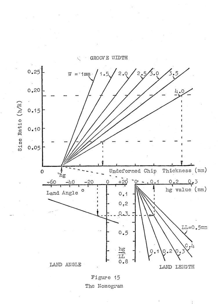
A nomogram was devised which incorporates the dimensions of the geometry of a simple grooved tool which.-have the most significant effect on the chip breaking performance.
These parameters are the groove width, the land length and the land angle. The nomogram is shown in figure 15. It comprises three graphs, each primarily concerned with one parameter of the groove, but all are interdependant. The land angle and land length graphs have a common axis, namely the hg/LL axis. The undeformed chip thickness,
(h) axis of the groove width graph is graduated in mm but no absolute values are marked, this is because the inter cept at h/R = 0 is dependant on the hg value determined from the land length and land angle graphs.
-The chart provides a guide to the performance of a chip breaker under specified cutting conditions, or
alternatively it can be used to select the optimum groove configurations required for a particular job. Whilst the nomogram is only numerically appropriate for a simple grooved tool the overall effects of changing the cutting conditions, when using tools with complex profiles, can be found by extrapolation. An explanation and example of how to use the chart are given in Appendix -8.
The reliability of the chart was examined by comparing the range of feeds for acceptable chip breaking in tests with the values predicted from the chart, a reasonable correla tion was found, some typical results are given in table 7*
Cutting speed has relatively little effect on chip
breaking performance and also the variation of material constant (see table 1) for plain carbon steels is slight v/hich indicates that the one chart can be used as a guide for a v/ide variety of cutting conditions and steel work pieces. The nomogram can, of course, be drawn to fit the user’s own tests and the "n^-value v/hich he finds most -appropriate.
5.3 Application of Computers.
but also the software is now so greatly advanced that the computer layman can write quite powerful programmes. These two facts lead to the inevitable transfer of the nomogram to a computer.
Many versions of the nomogram can be programmed to suit particular problem areas, or in fact a very versatile package could be written to cater for many models of use. To demonstrate the principle a simple program has been written for a BBC micro computer. This program will
accept any reasonable tool dimension and workpiece onaferial Qod qivas resolfs I
CHAPTER 6
THE INVESTIGATION INTO THE PERFORMANCE OP TOOLS WITH UMCOHVEHTIONAL
6.1 An Introduction to Recently Produced Tool Profiles. In’ recent times cutting tool manufacturers have designed around the 11 conventional” chip breaking groove ( which has a pcxrcvjlel land and a parallel groove) in order to improve the chip breaking performance and cfteV * to meet specific cutting conditions. It is unfortunate that communication between manufacturer and user is so poor that little is generally known°fhow the special features of these tools
operate or even how the fundamental variables such as land length and groove width affect the chip breaking feed range.
This lack of information leads to tools being tried and used in an ad-hoc manner which is b oth very time consuming for the user and does not necessarily result in the optimum tool shape for the particular application.
This work explains the effect of some ”special” features, for example, tapered grooves, multiple grooves and ”dimple” grooves. Explanation is given of how conventional theory can be extended to the unconventional features and, by demonstrating the similarity with the conventional groove, leads to a unified method of predicting chip
breaking performance from examination of the tool profile.
The description of a particular feature was not always simple since commercial inserts usually combine features, for example, the shallow grooves and multiple groove
problem was solved, whenever possible, by producing tools in the laboratory with the?j^1irticular feature which is to be examined*
It is, of course, impossible to reproduce the complex, sintered-in, contours of some commercial inserts but the object was to identify "profile-types" which could be recognised on a number of tools, and not to remake commercial tools. Each parameter was physically
investigated with all the available laboratory techniques e.g., the use of a quick stop device*
6.2 The Effect of Tapered Grooves on Chip Breaking
Performance.
If the probability of the chip avoiding the workpiece shoulder can be increased, that is by the helix angle of the chip being large, then the chip breaking performance is likely to be more favourable. It has been suggested that a tapered groove allows the chip coil to take up a helix wif'b ©feeder: ^>\Vch , however, as will be shown this did not
occur. In this investigation both a commercial insert and tools prepared in the laboratory were examined. The commercial tool was produced by "Valenite" and its form is shown in figure 16(a), it should be noted the tool has€+106,1 non-conventional features - a tapered groove and a shallow groove and a curved cutting edge. The tool
underwent a series of tests in which the feed was steadily increased and the chip radius v/as noted at each feed
setting. Since the chips were helical the radius of each edge of the chip was measured and the average recorded.
-30-Figure 16(b) shows the size ratio versus undeformed chip thickness relationship. It is clear that the relation ships for a simple grooved tool do not apply to the
Valenite tool and, unlike the case of a more conventional shallow groove tool, no approximations can he made* The nomogram is of no help for this particular tool*
A number of tools were prepared in the laboratory each with steadily widening grooves but the land remaining parallel (figure 17(a)). Very little effect could be
determined from the small tapers, the chips being as expected from a parallel groove, the results recorded in table 8 are for the widest taper angle produced - a taper of 27°. The comparison of the helix angle from straight and tapered grooves indicates that the taper has influence only at very small depths of cut. The helix angle is
equal to the chip flow direction as reported by Boothroyd (12) and this remains true whether the groove is tapered or not. Observing the chip bending process at very slow cutting speeds gives some insight into why the chip fails to be influenced by the angle of the back of the groove. The chip is seen to make contact at one point on the back edge of the groove only and does not therefore
recognise the shape of the groove. (Henriksen (3 ) reported that very little force is required to deflect the chip
and observed the chip curling as it met the nearest part of the grpove heel v/hich supports the supposition that the chip does not necessarily follow the shape of the back
of the groove.)
-Fine (13) described fan-shaped chips and these were
occasionally found in these tests (figure 17(b)).’ There was, however, no evidence that the taper formed the fan and it is expected that the edge of the chip furthest from the tool nose was carried by its own momentum into a
larger radius than the radius of the formed edge of the chip, thus producing a fan-shape.
Commercially tapered grooves have been used in boring
tools for quite a different purpose, that is directing the chip away from the cutting area. This appears to be the only advantage; the results did not show that the taper changed the helix angle, and the fan shaped chips which were sometimes produced are disadvantageous because they are less likely to break cleanly, and may form half
broken chips. The chip helix angle, being dependant on the chip flow direction would be increased by increasing the ratio between the tool nose radius and depth of cut. In predicting the chip breaking performance of tapered groove tools, the width of the narrowest part of the groove should be used when using the nomogram.
-6.3 The Influence of S.hallow droove Inlet Angles on Chip Breaking Performance.
It has been stated previously that the built-up edge angle of the chip will not exceed b5° and, therefore, a groove inlet angle of J4.50 will ensure that the chip is always free to take up its preferred radius with
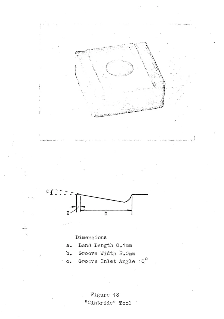
the life of the tool, particularly when using double sided inserts, therefore manufacturers tend to prefer shallow inlet angles. "Ciniride" is an example of such a manufacturer and an investigation of the action of one of their tools (shown in figure 18) is used to illustrate the behaviour of tools with shallow inlet angles.
The dimensions of the ’'Cintride" tool are shown in figure 18 and the tool holder presents the tool at a~7° rake angle to the work. The "Cintride*' tool was used over a range of feeds and the chips produced were collected and the outside radius was recorded. Figure 19 shows a graph
of both chip radius and size ratio against undeformed chip thickness. The type of chip at each feed was recorded, and particular attention was paid to the
undeformed chip thickness at which the chip began to use the groove and when chip breaking was acceptable. A number of ,fquick~stopM samples were acquired and prepared for
examination under the microscope in order to investigate conditions at the chip-tool interface and to establish Y/hich parts of the groove were in contact with the chip.
' The chip was observed as the tool was used at steadily increasing feeds. At low feeds it did not use the groove but curled naturally with a large radius. The chip began to use the groove at an undeformed chip thickness of
0 .13mm, chip breaking was acceptable from undeformed chip thickness values of 0.22mm and at an undeformed
From figure 19> three phases of chip formation can he identified. In the first phase, phase I the tool is
operating as a controlled contact length type; the groove does not interfere with the chip and it is assumed that the relationships referred to previously are valid
(although in this particular case the feed range is too small to verify this). The chip radius over this range is given by:
R = W
2 sin p>
where (2>= the built-up edge angle of the chip.
Over the next phase, phase II the chip radius is almost constant (changing only 0.6mm over 0.2mm change in
undeformed chip thickness) which indicates that the
built-up edge angle is equal to groove inlet angle. Any further increase in built-up edge angle is prevented since there is a reaction force acting on the built-up edge
from the bending of the chip against the groove heel* In the case of most tools v/hich have a groove inlet angle less than the maximum built-up edge angle the chip radius will remain constant for all subsequent increases in
from quick-stop specimens (figure 20) showed the chip-^o^( 'ConVaiarea extending into the groove. Under these
conditions the radius of the chip is:
E = W eff 2sin 10°
where W ^ is the effective "groove" width which is the nominal groove width plus the land length minus the chip tool contact length (W ^ - W+LL-CL). The contact length for a particular rake angle and workpiece is proportional to undeformed chip thickness. Typically, contact length is 1.5 times, or 2 times the undeformed chip thickness, the chip radius would then "become:
R = W+LL-2h 2sin 10°
The radii expected from this equation and "by using a contact length to undeformed chip thickness ratio of 1*5 are compared with the measured radius in table 9*
The nomogram has limited use in predicting the chip breaking performance of shallow groove tools, since the relationships are only valid for the first phase of chip forming described.
6. JLj. The M.oat Effect.
Many commercial tools have grooves in all four faces
nose radius and the chip direction is difficult to predict and may strike the groove obliquely (figure 21a). Slightly increased depths of cut will change the chip flow
direction and may cause the chip to hit the groove of the secondary cutting edge (figure 21b), or run along the
length of the groove (figure 21c). If the tool is operat ing in one of these areas, chip breaking will be
unpredictable. There will be a depth of cut where the chip width will be sufficient to ensure that the chip is always
curled by some part of the groove (figure 21d). The
proportion of the . ■ which makes contact with the groove does not need to be large since the force required to bend the chip is small.
6.5 The Influence of Multiple Groove on Chip Breaking
Performance
The Sandvik SNMM double groove tool (figure 22) was used to demonstrate the action of multiple grooves. This tool has double grooves in all four faces, therefore the depth of cut was selected to be always large enough to prevent the "moat effect" described earlier coming into operation.
The grooves of this tool are also shallow and the investiga tion into the "Cintride" shallow groove tool supported
this investigation. . '
The operation of this tool relies on the groove being shallow, ^° qIIov/J the area of chip-tool contact must move
into the groove (as occured in the case of the "Cintride" ^oc\)t
•altecoal-iveLj |4^ Is groox/^cpyi.cl vf\(( w^stagnant workpiece material
of this tool is shallower than that of the Cintride tools-so much tools-so that the operation of the tool, even at very low values of uct cannot he identified as typical of a conventional grooved type tool. The chip-tool contact moves into the groove at very low values of uct, quickly
causing crowded and overbroken chips.
A series of tests was undertaken in which the chip radii were noted for gradually increasing undeformed chip
thicknesses.
The results obtained are shown in figure 23 and it is clear that the theory of equations (1) to (5 ) does not apply. The results show two slopes, over two ranges of feed which correspond to first one groove operating then the second.
It is stated by the manufacturers that the groove nearest the cutting edge will operate at small values of uct, and the second groove will come into operation at high values of uct. This was found to be the case, but the transition from one groove to the other is not smooth, and there is a wide range of uct where breaking is unpredictable and
often unacceptable. The range of undeformed chip thickness over which acceptable chips were found, when the first
groove is operating, is very small.
"sees11 the first groove as a land and: uses the second groove. If the grooves were deeper, it was thought un likely that the area of chip-tool contact would ever
exceed the land of the first groove. In order to test this hypothesis a tool with deeper grooves was made in the
workshops and tested hy machining at an undeformed chip thickness high enough to give a contact length exceeding the first land and groove, hut the chip did not then, or at any higher feed, use the second groove of this tool.
Evidence of the action described hy Lundgren was obtained from quickly stopped specimens of the "Sandvik" tool. The photomicrograph (figure 21|) shows the dead metal zone extending over the first groove and therefore is not used for curling the chip. The photomicrograph does notj
iposikv^Uj show that the second groove is in operation this is assumed,
-In the tool of this test, the second groove appears to operate consistently above an undeformed chip thickness value of 0.7mm, which gives an estimated "land length"
of 1 ,ij.mm using the expression: contact length = 2 x undeformed chip thickness. This is a reasonable estimate; the
measured "land length" was 1.3mm. The graph of h/R against h, figure 23, shows the range of the two grooves; straight chips were produced at uc.t.below 0.15mm, the first groove operated between an uct of 0 .13mm and 0 #Z*mm, althought not always producing good chip types. Chip breaking
became inconsistent until an uct of 0.7mm when the second
-groove appeared to operate.
The nomogram will apply for the very small range of undeformed chip thicknesses below that which gives a
built-up edge angle equal to the inlet angle of the first groove. It may be possible to use the nomogram to
predict the land length required on the tool - it is unlikely to be able to predict the "land length" of the
second groove, (that is, the width of the first groove plus the land length) because the "land" is not flat and may cause the land angle - land length relationship to change, although Henriksen’s contact length formula
seemed to apply. The nomogram cannot be used to predict the range of feeds for acceptable chip breaking because the chip-tool contact length is not restricted to the land but moves into the first groove at low feeds.
6.6 The Influence of Change in Chip Cross Section on Chip Breaking Performance.
Both notched tools and waved cutting edges cause the chip to break more easily by changing the cross section of the chip. The waved cutting edge form can be considered as a -.series of wide notches. There is a range of cutting edge
In order to investigate the effect of changing the cross section of the chip a small, hemispherical notch was spark eroded in the land of a tool which had a conventional
groove (figure 25)* The notch was positioned close to, hut not interfering with the tool nose radius. Samples of chips over a range of feeds were collected, mounted and polished to show the cross section of the chip, and
photographed. The outlines of these chips are shown in figure 2 6 .
The chips at low values of undeformed chip thickness
followed the .contours of the land quite closely, giving the chip a ridged spine. The kinked cross section gives the chip a stiffer structure, thereby making the chip easier to break, as there is less chance of it being deflected sideways at the tool flank and additionally the chip has an increased moment of inertia. As the feed is increased the notch is filled with dead metal and the chip becomes almost rectangular. The degree of "kink" in the chip appears to be dependant on the undeformed chip thickness and the land length of the tool. The land lengths of the prepared tools were 0.18 and 0 .46mm. The chips from the tool with a 0 .46mm land length became almost rectangular at an undeformed chip thickness of 0 .6mm, whereas the chips produced by the tool with the shorter land reached a similar cross section at 0 .4mm undeformed chip thickness.
chips sometimes formed without using the hack of the groove hut this peculiarity was found only occasionally and there was insufficient evidence to identify the cutting conditions which caused this to happen. It was, therefore, noted hut not investigated further.
The action of the notch used in these experiments is harsh and a shallower notch could possibly be used to enhance the advantages, but avoid the shortcomings of ’this type of tool.
The change in cross section of the chip is usually much more severe with the notched tool than with the waved cutting edge, and there is evidence of severe deformation of the chip at high cutting feeds when using the notched tool. This is not found with the waved cutting edge tool and indicates undesirable friction conditions, when the chip is subjected to harsh changes in section.
Cutting with the notched tool produces a chip section which becomes more rectangular as the feed is increased, suggesting that the chip breaking range will be extended at the low feed end of the range. Overbreaking at a lower feed than that at which overbreaking would occur with an un-notched tool can be avoided if the tool is