Loading Calculation For an Improved Ventilation System in a Chassis Dynamometer Room
M.H. Amran, M.A.H. Mohamad, S. Othman and B.Basuno
1
Faculty of Mechanical and Manufacturing Engineering Tun Hussein Onn University of Malaysia (UTHM)
Parit Raja, Batu Pahat, 86400 Johor Malaysia
*Email: [email protected]
Abstract:
The chassis dynamometer room in the automotive laboratory UTHM is one of very few chassis dynamometer room available in Malaysia. Therefore, it is considered as a one of rare facilities for test concerning engine performances, fuel consumptions and exhaust emissions. SIRIM for instance, needs the equipment for experiments on new invented biodiesels. The room is already equipped by a ventilation system, but unfortunately this existing system is not sufficient to support activities conducted in the room, as high temperature and accumulated smoke in the room are obviously observed. Hence, the person in charge has to depend on natural ventilation which is windows and doors opening. However, the problem is still occurring. Therefore, health and comfort issues are crucial. Furthermore, reliability of the chassis dynamometer test results could be questioned due to the instability of temperatures and relative humidity in the room during experiments. In order to obtain good results both temperature and relative humidity in chassis dynamometer room shall be maintained at certain constant values during testing. In the present work the Indoor Air Quality (IAQ) in the chassis dynamometer room is has been proved to be poor, leading to hazardous and uncomfortable working environment. Thus, the development of an improved ventilation system is essential. Therefore, the present study is carried out to determine the ventilation rate and heat load needed for the chassis dynamometer room. From the results, the undersized existing ventilation system is of evident.
Keywords: Indoor air quality; Chassis Dynamometer room; Ventilation System; Loading calculation.
1. Introduction
Ventilating is the process of
"changing" or replacing air in any space to control temperature or remove moisture, odors, smoke, heat, dust, airborne bacteria, carbon dioxide, and to replenish oxygen. Ventilation includes both the exchange of air to the outside as well as circulation of air
system in a chassis dynamometer room, automotive laboratory, UTHM.
A dynamometer or "dyno" for short was a machine used to measure torque and rotational speed (rpm) from which power produced by an engine, motor or other rotating prime mover can be
calculated. A dynamometer can also be used to determine the torque and power required to operate a driven machine such as a pump [2].
The chassis dynamometer room in the automotive laboratory, UTHM, is a significant facility in tests or researches concerning engine performances, fuel
consumptions and exhaust emissions. SIRIM for instance, need the equipment for
experiments on new invented biodiesels. The room was equipped with a ventilation system. Unfortunately, it was obvious that the existing ventilation system was not sufficient to support activities conducted in the room. High temperature and accumulated smoke in the room was easy to be observed. As a result, in charge person has to depend on natural ventilation which was windows and doors opening. However, the problem was still occurring. Therefore, health and comfort issues are crucial [3].
In this case, the dynamometer needs a proper ventilation system to make sure the smoke from the combustion process can be removed from the tested room. In addition, the ventilation system was needed to maintain good air quality as well as to keep the engine room temperatures at acceptable range due to provide.
However, to support the activity in the room an improved new design of ventilation system such as intake/exhaust blowers is required.
2. Ventilation and Heat Loading Calculated
The investigated chassis dynamometer room is located in the automotive lab
UTHM. The total room area is 74327 square in and 147.36 in high, the room has two entrances; the main entrance X1, (107 in x 108 in) and the other one is closed during the working. In addition, there are two windows (70/in x 47/in, 117/ in x 47/ in), W1 and W2 respectively. Due to the insufficient at the existing ventilation system the person in change needs the aid of the natural
ventilation which is the door and windows opening.
The general layout of the chassis dynamometer room is shown in figure 1. Previous study has proved the IAQ in the chassis dynamometer room is poor, leading to hazardous and uncomfortable working environment [4].
Figure 1: The chassis dynamometer room
2.1 Ventilation Rate
In this section the equations to calculate the loading of the ventilation system are shown [5].
i. Room Volume = Floor Area ×Height
=5.9x7.9x3.1 =144.49m3 ii. Ventilation Rate = (Room
Volume)/60 (2)
= (144.49)/60 =2.41m3/s iii. Safety factors [6].
Room/Space Peak Loads=
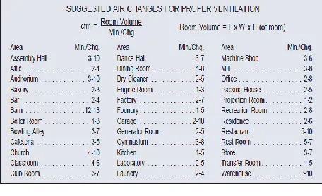
[image:3.612.318.533.306.520.2]1.1xVentilation rate (3) = 1.1x2.41 = 2.651m3/s Air change rate per hour (ACH) defined as 1-3 minute by ASHRAE standard for engine room as shown in figure 2 [7].
Figure 2: Suggested air change (ACH) for proper ventilation.
2.2. Heat Loading
Heat loses in dynamometer room [5].
i. Heating load for walls, glasses, floors, ceilings,
Q = UA∆T (4)
Q = Heat loss (Btu/hour @kW) U = Coefficient of transmission
A = Area calculated from plans ∆T = (Tdyno room - Tatmosphere)
= 47.6-28.5 = 19.1 oC
Tdyno room = Maximum temperature during experiment
= 47.6 oC
Tatmosphere = Average temperature in Batu Pahat, Johor (Jabatan
Meteorologi Malaysia) [8]. = (Tmax-Tmin)/2 = (33oC-24 oC)/2 =28.5 oC
The Heating load for walls, glasses, floors, ceiling, is shown in table 1.
[image:3.612.71.299.380.519.2]
Table 1: Heating load for walls, glasses, floor, ceiling in dynamometer room.
ii. Heat load from people
Q = N x (Total heat gain) x CLF (5) N= number of people in space, Total heat gain= from best available
source. Total of Sensible and latent heat gain from occupancy, table 7-1 [5].
CLF= cooling load factor, by hour of occupancy we chose CLF 1.0 with Medium Coefficient
of transmission (Btu/hr-ft2-F)
Heating load (Btu/hour)
Brick Wall 0.206 894.3 Wood wall 1 0.206 920.55 Wood wall 2 0.206 774.64 Wood wall 3 0.206 455.94
Glasses 1 0.89 631.58
Glasses 2 0.89 518.16
Floor 0.410 3941.2
Ceiling 0.206 1980.21
Total Heat
high density or 24-hr occupancy and/or if cooling off at night or during weekends [5].
Heat load from people
Q = N x (Total heat gain) x CLF = 3x (580+870) x1.0
= 4350Btu/hour (heat gain table 7-1 Heavy work) [5]
=4350x3.412 =14.84kW
iv. Total Heat of Equipment [5]. Heat from pendarflour lamp is
neglected because when the car was tested in the dynamometer room the lamp was not opened.
We assume the heat from Dynamometer machine is =0 Heat from car in tested (Pajero 2.4
diesel)
Conversion factors 1W=3.412Btu/hour 1Btu/hour=1x3.412 1W=1 J/s
Qcar = (mass flow rate) x HVdiesel (6) = 3.8 x 44.80
= 170.24 MJ/hour
Power of car = 50 kJ/s (from tested data sheet)
= 50 kJ/s x 3600 s/h =18360 kJ/h
=18.4 MJ/hour
Car Efficiency = (Power of car) / (Qcar) (7)
= 18.4/170.24 =0.11
Now we know that the heat loss from car =1-0.11 =0.89@89%
Total Heat car = Qcar x 0.89 =170.24x106x0.89
=151.51x10⁶J/hour
=151.51x106x (1/3600) =42.09kJ/s
=42.09kW
v. Total Heat Loading Q = 34.52+14.84+42.09 =91.45kW
vi. Safety factors [6].
Room/Space Peak Loads= 1.1xTotal
Heat loading (8) = 1.1x91.45
= 100.6kW
3. Improved Ventilation System
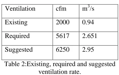
The existing ventilation system in the dynamometer room is equipped with an exhaust fan of 16 inch of diameter and 0.94m3/s or 2000 cfm ventilation rate, which is not sufficient [4]. Therefore we need to upgrade the ventilation system according to the calculation of 2.651m3/s or 5617 cfm ventilation rate needed in the room. The existing, required and suggested ventilation rate, is shown in table 1.The suggested fan size depends on ventilation rate requirement but the available size of fan are limited to the manufacturer’s product range [9].
Ventilation cfm m3/s
Existing 2000 0.94
Required 5617 2.651
[image:4.612.327.537.526.659.2]Suggested 6250 2.95
Table 2:Existing, required and suggested ventilation rate.
tested room are always greater than 30°C [4]. However, any chassis dynamometer room should be able to maintain stable temperature between 23°C and 26°C [3] to provide reliable test results. Furthermore, high temperature leads to uncomfortable working environment.
[image:5.612.82.287.233.408.2]An exhaust fan in addition will be allocated near the opposite end. The proposed ventilation design is shown in figure 3.
Figure 3: Propose ventilation
4. Summary
As a conclusions, the objective to calculated the ventilation system loading for a Chassis dynamometer room, in automotive laboratory, UTHM and to propose technical recommendations on improved ventilation systems base on the loading calculations were achieved where we can proof that the chassis dynamometer is in high pollution and uncomfortable for any test.
The suitable ventilation system loading calculation for the chassis dynamometer room and propose a new ventilation system design for the chassis dynamometer room were guided by result of the new loading calculation.
References
[1] McQuiston, parker, Spitler, Heating, Ventilating, and Air Conditioning (Analysis and Design) 6th Edition, 2005 Wiley.
[2] The new standard in chassis dynamometers,
http://www.dynapack.com/
[3] American Society of Heating, Refrigerating and Air-Conditioning
Engineers (ASHRAE),2002. HVAC Design Manual for Hospital and Clinics. Atlanta.
[4] A.M. Ejledi, M.H. Amran, M.A.H. Mohamad and S. Othman, Proceedings of the ICME 2010, Indoor Air Quality Measurement in a Chassis Dynamometer Room, 2010.
[5] Ali Vendavarz, Sunil Kumar, Muhammed, HVAC the handbook of Heating, Ventilation and Air Conditioning for Design and Implementation 1st Edition, 2007.
[6] HVAC Equations, Data, and Rules of Thumb 2nd Edition, 2008 Mc Grawhill.
[7] American Society of Heating, Refrigerating and Air-Conditioning Engineers (ASHRAE), 2008. Indoor Air Quality Guide.
[8] Average temperature in Batu Pahat, Johor (Jabatan Meteorologi Malaysia), http://www.met.gov.my/index.php?option=c om_content&task=view&id=3354&Itemid= 1930
[9] Industrial, ventilator and exhaust Fans product,