CFD STUDY ON THE HEAT TRANSFER IN VERTICAL
RIFLED TUBE WITH DIFFERENT HELICAL ANGLES
ABDURAUF.A.A.HAWIG
vi
Abstrak
Dalam penyelidikan ini, kajian “Computational Fluid Dynamics (CFD)” tentang
pemindahan haba dan pemantauan aliran bendalir pada tabung laras menegak dengan
dua sudut heliks (30o and 45o) yang berbeza telah dilaksanakan. Tabung laras menegak tersebut mempunyai diameter luar sebanyak 25mm, diameter dalaman maksimum sebanyak 18.8mm; diameter dalaman minimum sebanyak 17.50mm, ketebalan tetulang sebanyak 9.25, dan jumlah permulaan adalah empat. Simulasi CFD ini dijalankan ke atas orientasi menegak bagi tabung laras besi di bawah enam halaju masuk yang berbeza; 0.893, 1.765, 2.38, 2.897, 3.57, 4.166 m/s. Bendalir yang digunakan adalah air dan suhu awalnya adalah 298K. Objektif kajian ini adalah untuk menentukan pemindahan haba dan penurunan tekanan tabung laras dengan sudut heliks (30o and 45o) dibandingkan dengan keputusan tabung laras pada 60o sudut heliks. Keputusan tabung laras pada 30o sudut heliks menunjukkan suhu yang lebih tinggi untuk halaju masuk yang lebih rendah. Perbezaan suhu antara tabung masuk dan tabung luar adalah bersamaan 10.19K bagi 0.893 m/s halaju masuk. Sementara itu, bagi halaju masuk sebanyak 4.166 m/s, perbezaan suhu adalah 2K. Pola yang sama dijumpai bagi keputusan tabung laras pada sudut heliks 45o. Tambahan pula, perbezaan keputusan bagi tabung laras 30o dan 45o dengan tabung laras bersudut heliks 60o menunjukkan hanya sedikit penyimpangan. Penurunan tekanan bagi tabung-tabung bersudut heliks 30oand 45o pada halaju masuk yang lebih tinggi adalah masing-masing 17277.2 Kpa dan 19426.44Kpa. Sementara bagi
kedua-dua tabung pada halaju masuk yang rendah masing-masing bersamaan dengan 1295.9 Kpa, 1444.088Kpa. Keputusan tersebut menunjukkan penurunan tekanan
Abstract
CONTENTS
TITLE i
DECLARATION ii
DEDICATION iii
ACKNOWLEDGEMENT iv
ABSTRACT v
ABSTRAK vi
CONTENTS vii
LIST OF TABLES xi
LIST OF FIGURES xiii
LIST OF SYMBOLS xvii
CHAPTER 1 INTRODUCTION
1.0 Introduction 1
1.1 Objectives 3
1.2 Scope of study 4
1.3 Expected Results 5
CHAPTER 2 LITERATURE REVIEW
2.0 Introduction 6
2.1 Significance and background of heat transfer enhancement.
6
2.2 The critical heat flux (CHF) 7
2.3 Rifled tube 11
2.4 Helix angle 13
CHAPTER 3 EXPERIMENTAL METHODOLOGY
3.0 Literature review 14
3.1 Study methodology 14
3.2 Numerical methodology 18
3.2.1 Computational Domain 18
ix
3.2.3 Energy equation 21
3.2.4 Boundary Conditions 22
3.2.4 Mash study 23
CHAPTER 4 RESULTS AND DISCUSSION
4.1 Introduction 26
4.2 CFD analysis of rifled tube with 30o helical angle. 26
4.3 CFD analysis of rifled tube with 45o helical angle. 38
4.4 CFD analysis of rifled tube with 60o helical angle. 49
4.5 Comparing Results 60
4.5.1 Rifled tube of 30o and 60o helical angle. 60
4.5.2 Rifled tube of 45o and 60o helical angle 62
4..5.3 Rifled tube of 30o and 45o helical angle 64
4.5.4 Rifled tubes of 60o helical angle and different inner diameter.
66
CHAPTER 5 CONCLUSION, CONTRIBUTION AND
RECOMMENDATION
5.1 Introduction 68
5.2 Conclusion 69
APPENDIX FIGURES OF CFD SIUMLATION RESULT OF VERTICAL RIFLED TUBE
70
xi
LIST OF TABLES
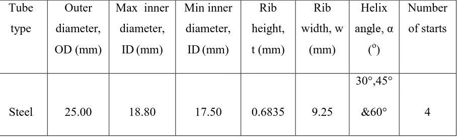
1.1 The dimensions of the rifled tube. 5
3.1 Gantt chart 17
3.3 The properties of water at temperature (298 k) 22
3.4 The properties of Steel at 300 k. 23
4.1 Temperature distribution along the tube with helical angle 30 °at six different inlet velocities (K).
27
4.2 The difference temperature at six different inlet velocities
with helical angle 30 ° (K).
28
4.3 Pressure distribution along the tube with helical angle 30 °at six different inlet velocities (Pa)
32
4.4 The difference pressure at six different inlet velocities with helical angle 30 ° (Pa).
33
4.5 Temperature distribution along the tube with helical angle 45 °at six different inlet velocities (K).
37
4.6 The difference temperature at six different inlet velocities with helical angle 45 ° (K).
38
4.7 Pressure distribution along the tube with helical angle 45 °at six different inlet velocities (Pa)
43
4.8 The difference pressure at six different inlet velocities with helical angle 45 ° (Pa).
44
4.9 Temperature distribution along the tube with helical angle 60 °at six different inlet velocities (K).
4.10 The difference temperature at six different inlet velocities with helical angle 60 ° (K).
49
4.11 Pressure distribution along the tube with helical angle 60 °at six different inlet velocities (Pa)
54
4.12 The difference pressure at six different inlet velocities with helical angle60 ° (Pa).
55
4.13 The temperature distribution for rifled tubes at 60o helical
angles with different inner diameter thickness.
xiii
LIST OF FIGURES
4.1 Temperature distributions along the tube at six different inlet velocities for rifled tube with 30° helical angle.
28
4.2 Relationship between drop temperature and six different inlet velocities for rifled tube with 30° helical angle.
29
4.3 Relationship between temperature and length of tube with 30° helical angle at inlet velocity 0.893m/s with 150 KW/m2.
29
4.4 Relationship between temperature and length of tube with 30° helical angle at inlet velocity 1.786m/s with 150 KW/m2.
30
4.5 Relationship between temperature and length of tube with 30° helical angle at inlet velocity 2.38m/s with 150 KW/m2.
30
4.6 Relationship between temperature and length of tube with 30° helical angle at inlet velocity 2.976m/s with 150 KW/m2.
31
4.7 Relationship between temperature and length of tube with 30° helical angle at inlet velocity 3.57m/s with 150 KW/m2.
31
4.8 Relationship between temperature and length of tube with 30° helical angle at inlet velocity 4.166m/s with 150 KW/m2.
32
4.9 Pressure distributions along the tube at six different inlet velocities for rifled tube with 30° helical angle.
33
4.10 Relationship between drop pressure of six velocity m/sce of a vertical rifled tube with 30° helical angle and 1m length.
34
4.11 Relationship between drop pressure and length of tube with 30° helical angle at inlet velocity 0.893m/s
35
helical angle at inlet velocity 1.786m/s
4.13 Relationship between drop pressure and length of tube with 30° helical angle at inlet velocity 2.38m/s
36
4.14 Relationship between drop pressure and length of tube with 30° helical angle at inlet velocity 2.976m/s
36
4.15 Relationship between drop pressure and length of tube with 30° helical angle at inlet velocity 3.57m/s
37
4.16 Relationship between drop pressure and length of tube with 30° helical angle at inlet velocity 4.166m/s
37
4.17 Temperature distributions along the tube at six different inlet velocities for rifled tube with 45° helical angle.
39
4.18 Relationship between the difference temperature and six different inlet velocities for rifled tube with 45° helical angle.
40
4.19 Relationship between temperature and length of tube with 45° helical angle at inlet velocity 0.893m/s with 150 KW/m2.
40
4.20 Relationship between temperature and length of tube with 45° helical angle at inlet velocity 1.786m/s with 150 KW/m2.
41
4.21 Relationship between temperature and length of tube with 45° helical angle at inlet velocity 2.38m/s with 150 KW/m2.
41
4.22 Relationship between temperature and length of tube with 45° helical angle at inlet velocity 2.976m/s with 150 KW/m2.
42
4.23 Relationship between temperature and length of tube with 45° helical angle at inlet velocity 3.57m/s with 150 KW/m2.
42
4.24 Relationship between temperature and length of tube with 45° helical angle at inlet velocity 4.166m/s with 150 KW/m2.
43
4.25 Pressure distributions along the tube at six different inlet velocities for rifled tube with 45° helical angle.
44
4.26 Relationship between drop pressure of six velocity m/sce of a vertical rifled tube with 45° helical angle and 1m length
45
4.27 Relationship between drop pressure and length of tube with 45° helical angle at inlet velocity 0.893m/s
xv
4.28 Relationship between drop pressure and length of tube with 30° helical angle at inlet velocity 1.786m/s
46
4.29 Relationship between drop pressure and length of tube with 30° helical angle at inlet velocity 2.38m/s
47
4.30 Relationship between drop pressure and length of tube with 30° helical angle at inlet velocity 2.976m/s
47
4.31 Relationship between drop pressure and length of tube with 45° helical angle at inlet velocity 3.57m/s
48
4.32 Relationship between drop pressure and length of tube with 45° helical angle at inlet velocity 4.166m/s
48
4.33 Temperature distributions along the tube at six different inlet velocities for rifled tube with 60° helical angle.
50
4.34 Relationship between the difference temperature and six
different inlet velocities for rifled tube with 45° helical angle.
51
4.35 Relationship between temperature and length of tube with 60° helical angle at inlet velocity 0.893m/s with 150 KW/m2.
51
4.36 Relationship between temperature and length of tube with 60° helical angle at inlet velocity 1.786m/s with 150 KW/m2.
52
4.37 Relationship between temperature and length of tube with 60° helical angle at inlet velocity 2.38m/s with 150 KW/m2.
52
4.38 Relationship between temperature and length of tube with 60° helical angle at inlet velocity 2.976m/s with 150 KW/m2.
53
4.39 Relationship between temperature and length of tube with 60° helical angle at inlet velocity 3.57m/s with 150 KW/m2.
53
4.40 Relationship between temperature and length of tube with 60° helical angle at inlet velocity 4.166m/s with 150 KW/m2.
54
4.41 Pressure distributions along the tube at six different inlet velocities for rifled tube with 60° helical angle.
55
4.42 Relationship between drop pressure of six velocity m/sce of a vertical rifled tube with 60° helical angle and 1m length
56
4.43 Relationship between drop pressure and length of tube with 60° helical angle at inlet velocity 0.893m/s
4.44 Relationship between drop pressure and length of tube with 60° helical angle at inlet velocity 1.786m/s
57
4.45 Relationship between drop pressure and length of tube with 60° helical angle at inlet velocity 2.38m/s
58
4.46 Relationship between drop pressure and length of tube with 60° helical angle at inlet velocity 2.976m/s
58
4.47 Relationship between drop pressure and length of tube with 60° helical angle at inlet velocity 3.57m/s
59
4.48 Relationship between drop pressure and length of tube with 60° helical angle at inlet velocity 4.166m/s
59
4.49 Temperature distribution along of the tube for rifled tubes with 30°and 60° helical angles.
60
4.50 Pressure distribution along of the tube for rifled tubes with 30°and 60° helical angles.
61
4.51 Temperature distribution along of the tube for rifled tubes with 60°and 45° helical angles.
62
4.52 Pressure distribution along of the tube for rifled tubes with 45°and 60° helical angles.
63
4.53 Temperature distribution along of the tube for rifled tubes with 30°and 45° helical angles.
64
4.54 Pressure distribution along of the tube for rifled tubes with 45°and 30° helical angles.
65
4.55 Temperature distribution along of the tubes for rifled tubes with 60° helical angles with different thickness.
xvii
LIST OF SYMBOLS AND ABBREVIATION
CFD Computational Fluid Dynamics
K Kelvin
o
C Degrees Celsius
CHF Computation Heat Flux
(o) Helix angle
w Width
Cp Specific heat Dansity
P Prssuer
τw Wall Shear Stress uτ Friction Velocity
ν Kinematic viscosity
Ue Velocity
Re Reynolds Number
Skin Friction Coefficient
Δp Pressure Drop
Dynamic Viscosity
k Thermal Conductivity
u, v, w Velocity component in( x, y ,z ) coordinates system
Fluctuating velocity
Average pressure
f Force component in( x, y ,z ) coordinates system
The viscous dissipation term
t The Time
e Internal energy of mixture, per unit mass
xix
LIST OF APPENDICES
APPENDIX TITLE PAGE
A FIGURES OF CFD SIUMLATION
RESULT OF VERTICAL RIFLED TUBE
70
B TYPICAL CONTOUR OF STATIC
TEMPERATURE (K)
CHAPTER 1
CFD STUDY ON THE HEAT TRANSFER IN VERTICAL RIFLED TUBE
WITH DIFFERENT HELICAL ANGLES
INTRODUCTION
The study will describe a computer based software study and its results, analysing heat transfer and fluid flow in rifled tubes. The software used for the study is called GAMBIT and FLUENT. GAMBIT is a general-purpose pre-processor for CFD analysis, which allows engineers access into the CFD world is used to draw the objects FLUENT, the world leader in computational fluid dynamics software, is used
to analyze the results.
2
exploit any heat source and are generally preferred in high pressure applications since the high pressure water/steam is contained within small diameter pipes which can withstand the pressure with a thinner wall.
The boiler system consists of circuits, pressure grids and connecting tubes. Therefore, the study of temperature history (heat transfer), change in pressure, steam velocity and fluid flow in a vertically rifled tube are essential for the safety and
efficiency of the tube boiler. Prediction of liquid one-phase flow frictional pressure drop in flow boiling process is of key importance in designing thermal process equipment in various industries such as thermal energy plant, refrigeration and heat pump system, chemical process engineering and others. On one hand, if a fixed flow is required, the pressure drop in a system determines the power input of a pumping system. If, on the other hand, the available pressure drop in a system is fixed, the relationship between the pressure drop and the resultant system velocity is of importance in determining velocity-dependent parameters, such as heat transfer coefficient, mass flux and heat flux limitation. However, the prediction of vapour liquid one-phase frictional pressure drop in flow boiling still needs investigation because it is usually greater and usually very difficult to estimate.
In this research, software based studies will be carried out on the fluid flow in a vertical rifled tube (one-phase), considering 3 different helical angles.
The specifications of the angles in the tubes are as follows:
1. Rifled tube with 60 degree angle (results are available from previous studies and will be used as comparison baseline)
2. Rifled Tube with 30 degree helical angle
3. Rifled Tube with 45 degree helical angle
determine the time required to reach the boiling point. The results will be illustrated graphically in a temperature – time diagram.
With the development of enhanced heat transfer technology over the last decades, various enhanced heat transfer tubes have been developed for the purpose of
improving heat transfer coefficients and saving energy consumption. However, in general, heat transfer is increased in the enhanced heat transfer tubes by
accompanying an increase of one-phase frictional pressure drop whereby the most efficient angle will be determined during the study.
Spirally internally rifled tube is one of these types of enhanced heat transfer tubes which can enhance flow boiling heat transfer and critical heat flux (CHF)
development of science and technology. Enhanced heat transfer technology has achieved great development and found wide applications in various industries over the past decades. Enhanced heat transfer is generally called the second generation heat transfer technology and it plays a very important role in the development, utilization, and saving of energy (Wedd et al 2009). Whether for practical use or for theoretical value, the study of enhanced heat transfer elements is of great
significance. For that aspect of flow boiling which involves heat transfer
enhancement, quite a few studies have been conducted to improve heat transfer rate and energy efficiency. An exhaustive compilation of the relevant literature has been presented (Almeida.et al.,2008) , Enhanced heat transfer Technology is generally classified as active, passive, and compound heat transfer enhancement technologies, respectively, which combines at least two heat transfer enhancement methods. Passive heat transfer enhancement technology is more practical and is easily
implemented because it does not consume external power. Various flow boiling heat
transfer enhancement methods have been developed over the past years, for example, rough surface, electrostatic field, additives for fluids and so on (Mott et al .,2006) Of these, the spirally internally rifled tube is a type of enhanced tube which is able to enhance flow boiling heat transfer and critical heat flux (CHF).
4
studies of flow boiling in internally rifled tubes have been carried out over the past years in this study Numerical analysis will be carried out on vertical rifled tubes to determine the fluid flow properties, the heat transfer and pressure drop across the tubes in the different models. Heat will be supplied electrically. Heat transfer rate will be determined by calculations with the software as well as the velocity of the fluid. The fluid flow velocity will be controlled as input parameter in the software.
The pressure drop in the tube and the heat enhancement factor of ribbing the tube will also be determined by software analysis.
1.1OBJECTIVES OF STUDY
1. To determine the flow rate and pressure characteristics in a vertical
positioned rifled tube helical angle 30°, 45° and 60°.
2. To determine the heat transfer in a vertical rifled tube (determine the time
required to reach the boiling point).
3. To determine the pressure drop in a vertical rifled tube.
1.2 SCOPE OF STUDY
Computer analysis will be used to determine the characteristics of fluid flow in the
rifled tube. Table 1.1: shows the dimensions of the rifled tube the scope of study are:-
i. Water will be used as the fluid medium (one-phase).
ii. Riffled tube will be analyzed with two different helical settings; 30° and
45° degrees and compared with previously studied of 60 degrees.
Table 1.1: The dimensions of the rifled tube.
Tube type
Outer diameter, OD (mm)
Max inner diameter,
ID(mm)
Min inner diameter, ID(mm)
Rib height, t (mm)
Rib width, w
(mm)
Helix angle, α
(o)
Number of starts
Steel 25.00 18.80 17.50 0.6835 9.25
30°,45°
&60° 4
1.3 Expected Results.
CHAPTER 2
LITERATURE REVIEW
2.1Significance and background of heat transfer enhancement.
Heat transfer, heat flow, heat exchange or transfer of thermal energy all implies to the movement of heat from one place to another. Heat transfer occurs when an object has temperature different to that of its surroundings and this happens until temperature of both reaches to equilibrium. The heat transfer always occurs in the direction from high temperature to low temperature region which is accordance with the second law of thermodynamics. In engineering, energy transfer by heat between objects is classified as either heat conduction, also called diffusion, of two objects in contact, by fluid
convection, which is the mixing of hot and cold fluid regions, and by thermal radiation, the transmission of electromagnetic radiation described by black body theory (Loomis and Maris, 1994). However, engineers also consider the transfer of mass of differing chemical species, either cold or hot, to achieve transfer of heat.
Heat exchange has its application in various fields like aviation and space systems; energetic, chemical and petroleum refining, food industries, refrigerating,
air-conditioning and cryogenic engineering; materials, steel, iron and metallurgical industries and heating and hot water supply systems etc.(Kakaç and Liu, 2002). The investigation and development of the better heat transfer performance of heat exchangers is denoted as heat transfer enhancement. This is nothing but the increase in the heat transfer
noteworthy growth in recent years and is of extreme significance in heat exchanger strategies. The fact that the enhanced heat transfer exchangers can provide more compact, lightweight and less expensive exchangers has been the backbone of this growth.
Enhancement techniques are characteristically set apart into two groups: „passive‟ and „active‟ techniques. In passive techniques special surface geometries or fluid additives are
used for enhancement. In the active enhancement there are techniques like heated surface rotation, surface vibration, fluid vibration, electrostatic fields and suction at the heated surface. The active techniques are efficient in dropping the wall superheat and
augmenting the critical heat flux, but the practical applications are confined, possibly due to the difficulty in providing the mechanical or electrical effect (Bergles, 1997).
Utilization of two or more of these techniques concurrently can produce an enhancement that is greater than the specific techniques applied discretely.
2.2The critical heat flux (CHF)
Critical heat flux (CHF) is the heat flux at which a boiling crisis happens accompanied by
an abrupt raise of the heat transfer surface or decreasing the efficiency of the heat transfer
rate. The CHF inflicts a limit in constructing and accomplishing boiling heat transfer
machinery in macroscopic heat transfer excahangers in power manufacturing units like
the nuclear, fusion and fossil power stations. Besides in microscopic heat transfer devices
like heat pipes and micro channels for cooling electronic chips. Therefore, a raise in the
critical heat flux could add to the safety factor and permits for more economical devise
and operations at elevated heat fluxes (Chang et al., 2006). The higher the capacity of the
nuclear power plant or the fossil boilers is the more will be the requisite heat load per unit
transfer area. The utmost heat flux may be elevated more than 10 MW/m2 and hence
special heat transfer maneuvers are mandatory. Nucleate boiling is the most effectual heat
transfer process and the upper boundary of this is stipulated by the CHF. Henceforth,
attempts have been discharged to explicate the regime of nucleate boiling. The
8
having substantial research of related work accounted in the literature (Chang et al.,
2006).
From the past studies and recent researches, it has been found that the main thermal resistance to the convective heat transfer is because of the existence of laminar sub-layer on the heat-transferring surface. The ribs break the laminar sub-layer and produce local wall turmoil because of the flow separation and reattachment among the consecutive ribs, that diminishes the thermal resistance and very much improves the heat transfer. Anyhow, the artificial roughness used may result in higher friction and thus
higher pumping power necessities. For that reason, it is advantageous that the turbulence ought to be created in the vicinity of the wall, i.e. only in the laminar sub-layer region, which is accountable for thermal resistance. That's why, the pains of researchers have been intended towards discovering the roughness shape and arrangement that could break the laminar sub-layer and improve the heat transfer coefficient to the maximum with the least amount pumping power penalty (Kamali and Binesh, 2008).
There were investigations on the effects of rib height, rib spacing, and Reynolds number. The friction factor is shown to be directly proportional to the rib height and inversely proportional to the rib spacing in the range investigated. Dipprey and Sabersky formulated a friction similarity law and a heat momentum transfer analogy for flow in rough tubes (Dipprey and Sabersky, 1963). Webb and Eckert also contributed by
developing the heat transfer and friction factor correlations for turbulent air flow in tubes having repeated rib roughness (Webb et al., 1971). The heat transfer enhancement was investigated and Zhang et al. reported that the addition of grooves in between adjacent square ribs could enhances this capability of the surface greatly with almost same pressure drop penalty (Zhang et al., 1994). The aid of artificial roughness in the form of repeated ribs in these respects has been established to be an proficient technique of enhancing the heat transfer to fluid flowing in the duct. Katto has broadly studied CHF
for forced convection boiling in various case of working conditions based on dimensional analysis. He collected CHF data by means of seven different fluids and the data were
Tubes that have a transverse repeated-rib roughness with rectangular cross section have been examined first by Webb et al. (Webb et al., 1971). With the aid of the law of the “wall similarity” and heat-momentum analogy he put forth a few correlations where
the friction factor is expressed as a function of the dimensionless geometric parameters and the Reynolds number, wheras the Stanton number is expressed as a function of the same variables and the Prandtl number together. This study was extended to the effect of the rib helix angle by Gee and Webb (Gee and Webb, 1980). Based on the
heat-momentum transfer analogy, Withers (Withers, 1980) developed correlating equations for
the heat transfer and pressure drop in tubes comprising simple and multiple helical ridges inside. These correlations were derived by experimental data attained with water in the Reynolds number range 10000-120000 and Prandtl number range 4-10. Heat transfer enhancement of up to 2.5 to 3 was accounted. A similar study of heat transfer
enhancement was conducted by Yampolski using a spirally fluted tube (Yampolski, 1983). He illustrated that the swirl in the flow owing to the helical flutes augments turbulent exchange on both interior and exterior of the tube with no substantial increase in the friction factor. Turbulent flow investigations dealing with pressure drop and heat transfer coefficient in the doubly-fluted tubes were also performed by Richards et al (Richards et al., 1987). In the study, out of the twelve different geometries that were analyzed only some of them yield an enhanced performance, expressed by the authors in terms of heat exchanger volume diminution.
Another study by Garimella et al.(Garimella et al., 1988) expressed the
performance of spirally enhanced tubes in terms of a single non dimensional geometric parameter, the severity. Here also the turbulent flow is considered and it has shown that for severity values between 0.001 and 0.01 the heat transfer increase is escorted by moderately low friction factor increase, hence proving the competence of similar variety of geometries. Garimella and Christensen (Garimella and Christensen, 1993) have
inspected the fluid flow in annuli produced by inserting spirally fluted, indented and ribbed tubes within a smooth outer tube. In order to have better understanding of the
10
promoting the secondary flow and consequently in improving the convective heat transfer.
Several attempts were made by the researchers to enhance the CHF by
maneuvering the internal flow and changing the fuel assembly. According to (Gambill et al., 1960) when the flow in a tube is directed by twisted tape, a helical coil or a grooved surface (rifled tube), a swirl flow can be generated. By the centrifugal force generated by
the swirling motion of the fluid, liquid is forced to flow on the tube surface and vapor is
forced to flow along center line of the tube. Consequently, local velocity of the flow is
increased compared to that in a smooth tube under the same mass flux. Therefore, the
swirl motion of the flow can contribute to enhancement of the CHF. (Gambill et al.,
1960) were the first to study the effect of flow swirling on heat transfer and its effect on
the CHF. They attained high CHFs, 118 MW/m2 for water and 28 MW/m2 for ethylene
glycol. The experiements of CHF under a subcooled boiling region were also performed
by some others later (Araki et al., 1989; Celata et al., 1994). Further, CHF experiments
for one-sided heating were also conducted to study the effect of a one-sided heat load in a
PFS like divertor in fusion reactors (Boscary et al., 1999).
So many literatures are available with the data presenting the rifled tube yields, which have significant enhancement in heat transfer and CHF (Cheng and Xia, 2000; Nishikawa et al., 1972; Swenson et al., 1962; Whalley, 1979). The chief application of rifled tubes consists of coal fired boilers and fusion divertors. Investigations with experiments on boiler application are conducted at high pressure and high quality (~22 MPa, x>1 ). In the spiral internally rifled tubes, the CHF can be enhanced by a factor of 1.3–1.6 when compared to a smooth tube (Cheng and Xia, 2002; Kim et al., 2005). On their study on four headed rifled tube with an average inner diameter 17 mm, Iwabuchi et al., (1982) found that at a pressure beyond 20.6 MPa, the improvement of the CHF vanished. Cheng and Xia, (2002) performed a parallel study and found that the
enhancement effect is evident from 10 MPa to 19 MPa. Anyhow, there was no noticeable enhancement at 21 MPa. When the pressure reached a critical pressure of approximately
divertor applications, the works are conducted at low pressure and low quality (~ 1 MPa, x<0)(Boscary et al., 1999).
2.3Rifled tube
During the 1970s and near the beginning 80s, the cost of the energy began to increase
spectacularly. As a result, the demand for energy-efficient air conditioning products also enlarged. In the early 1980s, the heat exchanger industry‟s contributed to the
commercialization of rifled-tube heat exchangers. Ahead of introduction of rifled tubes, the designer normally added more heat exchanger surface to hoist the effectiveness of an air conditioner (Shinohara et al., 1987). At present, due to the improved heat transfer characteristics of rifled tubing, designers can amplify efficiency without expanding the size of air conditioning components. The rifled tubing was developed to augment the performance of evaporators and condensers in two-phase refrigerant flow applications. The enhancement in heat transfer is due mainly to the 50% to 60% increase in internal surface area over plain tube, in this manner plummeting the liquid refrigerant film thickness (Kim et al., 2005).
As a result of reduced film thickness, there is an increased effective temperature difference among the tube wall and the refrigerant gas-liquid interface, and offers further heat transfer potential. In addition, in evaporator coils (depending on refrigerant
velocity), the rifled tube facilitates in promoting the annular flow, that results in the increase in the amount of wetted surface area for evaporation. The tube-side heat transfer coefficient for rifled tubing is as much as two and one-half to three times as compared to that of plain tube for condensing and evaporating settings.
The design of the ridges in rifled tubing is provided to improve performance in both condensers and evaporators; however, should have enough strength to diminish
12
proven to be effective (Lee and Chang, 2008). When compared to the condenser that has has desuperheating and subcooling sections, the evaporator coil has a higher percentage of its internal surface area in two-phase flow.
The research on rifled tube has been since long time and many researchers published article on the use of it in the heat exchange behavior (Lee and Chang, 2008; Smith et al., 1968; Yang et al., 2010). Tucakovic et al., (2007) used the evaporating tubes in the steam boilers with the intention of increasing the steam–water mixture
turbulization and to prevent the burnout of tubes walls. The rifled evaporating tubes and
the working fluid forced circulation are applied in the steam boiler at the Thermal Power Plant “Kolubara B” that is being built by the Electric Power Utility of Serbia. Lee and
Chang, (2008) performed a study of post-dry out heat transfer with a directed heated smooth tube and rifled tubes using vertical R-134a up-flow to look into the heat transfer distinctiveness in the post-dryout region. Three types of rifled tube that have dissimilar rib height and width were used to study the effects of rib geometry and match up with the smooth tube, using a mass flux of 70–800 kg/m2 s and a pressure of 13–24 bar
(corresponding to an approximate water pressure of 80–140 bar). The same study also showed that the heat transfer correlation for rifled tubes was also obtained as a function of rib height and width with the amendment of the smooth tube conjunction.
In order to investigate the heat transfer and friction behaviors of the rifled tube with vertical upward flow, Yang et al., (2010) from China used rifled tube in the water wall design of a 600MW supercritical CFB boiler. An in-depth experiment was
conducted in the range of pressure from 12 to 30MPa, mass flux from 230 to
1200kg/(m2s), and inner wall heat flux from 130 to 720kW/m2. The wall temperature distribution and pressure drop in the rifled tube term were acquired from this experiment. Their experimental results demonstrate that the rifled tube can successfully avoid the incidence of Departure from Nucleate Boiling (DNB) and maintain the tube wall
The majority of the researchers focused on performing experimental based on a conventional rifled tube, rather than enhancing it. The recirculation of the fluid induced by the fins augments the heat transfer only for Prandtl number greater than 5. A
numerical technique for predicting the friction factor and the heat transfer in spirally fluted tubes and this has been proposed by Iwabuchi et al., (1982). According to this technique the flute region is modeled as a porous substrate, with direction reliant permeability that influences the flow field in very much the similar way as the spiral flutes. The Nusselt number values obtained with the numerical simulation are in good
agreement with their experimental data for Reynolds number below 500. Preliminary tests (Kohler and Kastner, 1986) confirmed that the presence of the helical ridging yields a noteworthy heat transfer intensification also in the laminar field and recommended the opportunity of additional study in this research, the fluid flow characteristic of the rifled tube will be carefully monitored and analyzed. In comparison to the smooth tube, the effect of the inner surface geometry of the tube on varying parameters will be intensively established.
2.4 Helix angle
In mechanical engineering, a helix angle is the angle between any helix and an axial line on its right, circular cylinder or cone (Geerts et al., 2002). General applications are screws, helical gears, and worm gears. The helix angle references the axis of the cylinder, differentiating it from the lead angle, which references a line perpendicular to the axis. The helix angle is the geometric complement of the lead angle and the angle is measured in degrees. According to (Webb et al., 1971) the range of geometricparameters were
number of rib starts (18 to 45), helixangle (25 to 45 deg), and rib height (0.33 to0.55 mm). These geometries supplies data on a new classof internal enrichment that is typical
CHAPTER 3
METHODOLOGY
Develops sufficient background of the research based on past study by other researchers and therefore gains an insight into the challenges faced by the vertical rifled tube.
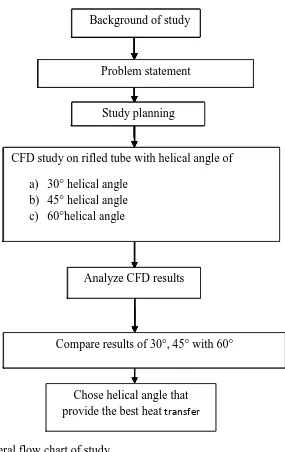
3.1 Study methodology
Figure 3.1: General flow chart of study
Background of study
Problem statement
Compare results of 30°, 45° with 60° CFD study on rifled tube with helical angle of
s) 30° helical angle t) 45° helical angle u) 60°helical angle
Study planning
Analyze CFD results
Chose helical angle that provide the best heat transfer
Background of study
Problem statement
Study planning Background of study
Problem statement
Study planning Background of study
Problem statement
CFD study on rifled tube with helical angle of
p) 30° helical angle q) 45° helical angle r) 60°helical angle
Study planning Background of study
Problem statement
CFD study on rifled tube with helical angle of
m) 30° helical angle n) 45° helical angle o) 60°helical angle
Study planning Background of study
Problem statement
Analyze CFD results
CFD study on rifled tube with helical angle of
j) 30° helical angle k) 45° helical angle l) 60°helical angle
Study planning Background of study
Problem statement
Compare results of 30°, 45° with 60° Analyze CFD results
CFD study on rifled tube with helical angle of
g) 30° helical angle h) 45° helical angle i) 60°helical angle
Study planning Background of study
Problem statement
Compare results of 30°, 45° with 60° Analyze CFD results
CFD study on rifled tube with helical angle of
d) 30° helical angle e) 45° helical angle f) 60°helical angle
Study planning Background of study
Problem statement
Chose helical angle that provide the best heat transfer
Compare results of 30°, 45° with 60° Analyze CFD results
CFD study on rifled tube with helical angle of
a) 30° helical angle b) 45° helical angle c) 60°helical angle
Study planning Background of study
16
Table 3.1 Gantt chart
[image:33.612.115.543.388.689.2]18
3.2numerical methodology
3.2.1 Computational Domain
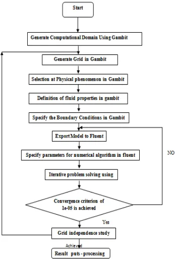
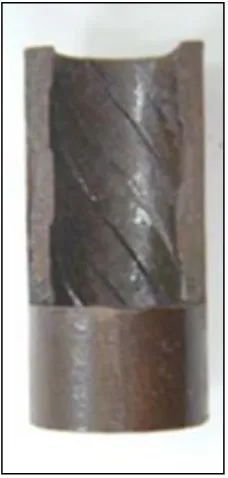
The commercial CFD code FLUENT (FLUENT, 6.3.) has been used to analyze the model flow characteristics of rifled tube. Modeling and mesh generation however have been performed in Gambit environment. Water has been taken as the fluid medium.
[image:34.612.114.541.382.478.2]Figure 3.3 shows the schematic diagram of the ribbed tube model. Table 3.2 on other hand, shows the dimensions of the rifled tube with the different helix angles. Also figure 3.6 shows the schematic diagram of computational domain, for schematic diagram of the Rifled tube has shown in figure 3.4. In additional to this, drawing of the Rifled tube which generated in GAMBIT shown in figure 3,5.
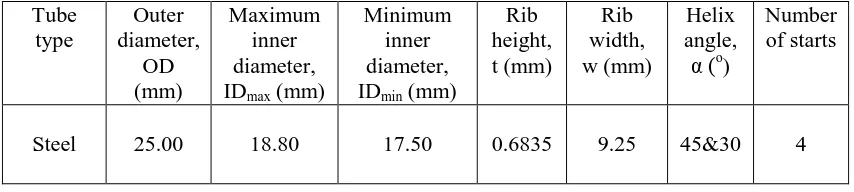
Table 3.2: The dimensions of the rifled tube.
Tube type Outer diameter, OD (mm) Maximum inner diameter, IDmax (mm)
Minimum inner diameter, IDmin (mm)
Rib height, t (mm) Rib width, w (mm) Helix angle,
α (o
)
Number of starts
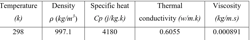
Figure 3.3: Computational domain.
[image:35.612.271.385.441.680.2]20
Figure.3.5A portion of the numerical domain generated in GAMBIT.
3.2.2Governing Equations
The following steady-state 3-D equations in Cartesian coordinates form will be use to
solve numerically for a Newtonian, incompressible fluid. Continuity Equation:
0
z w y v x u
(3.1)
x –component
y -component
z -component
Based on literature review, the Standard k - ε Model will be used in this study.
3.2.3 Energy equation
The modified form of the first law of thermodynamics applied to an element of fluid
states that the rate of change in the total energy (intrinsic plus kinetic) of the fluid as it flows is equal to the sum of the rate at which work is being done on the fluid by
external forces and the rate on which heat is being added by conduction,( P.K. Nagarajan et al,2009).
22
3.2.4 Boundary Conditions
Flow is considered to be turbulent as the Reynolds number range between 104 to 5×10⁴ were used. The properties of water were taken at temperature 25 (298 k), as show in
[image:38.612.127.531.72.144.2]table 3.3. The type of tubes used in this analysis is Steel and the properties for tube at 25oC are show in table 3.4.The heat flux was applied to heat up the wall of rifled tube. Figure 3.6 shows the boundary conditions.
Where:-
V: is the velocity, the results have been got at six velocities (0.893, 1.786, 2.38, 2.976, 3.57, 4.166).
[image:38.612.132.536.515.580.2]T: is the temperature (298k). h: is the heat flux (150KW/m2)
Table 3.3 .The properties of water at temperature (298 k).
Temperature
(k)
Density
(kg/m3)
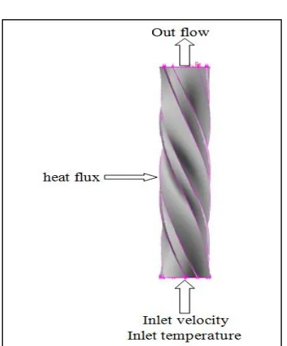
Specific heat
Cp (j/kg.k)
Thermal conductivity (w/m.k)
Viscosity
(kg/m.s)
Table 3.4-The properties of Steel at 300 k.
Figure.3.6: Boundary Conditions
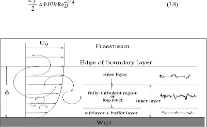
3.2.5 Mash study
For standard wall functions, each wall-adjacent cell’s centroid should be located within the log-law layer (figure 3.4).
300 30
p
y (3.6)
How to estimate the size of wall-adjacent cells before creating the grid:
v y y v u
u y
yp p / p p /
, u w/ Ue Cf /2 (3.7) Type of tube Density
(kg/m3)
Specific heat
Cp (j/kg.k)
Thermal conductivity (w/m.k)
24
Where:
τ
wis the Wall Shear Stress (kg.s−2.m−1)u
τ is the Friction Velocity(u
τ= (τ
w/ρ)
1/2) (m.s
−1)
ρ
is the Density (kg.m−3)ν
is the Kinematic viscosity (m2.s−1)Ue is the velocity (m/s)
The skin friction coefficient ( ) for duct can be estimated from empirical
correlations: :( www.Fluentusers.com)
4 / 1
Re 039 . 0 2
D
f C
[image:40.612.116.543.310.571.2](3.8)
Araki, M., Dairaku, M., Inoue, T., Komata, M., Kuriyama, M., Matsuda, S., Ogawa, M., Ohara, Y., Seki, M. and Yokoyama, K., 1989. Burnout experiments on the externally-finned swirl tube for steady-state and high-heat flux beam stops. Fusion Engineering and Design 9, 225-230.
Bergles, A.E., 1997. Heat transfer enhancement—the encouragement and accommodation of high heat fluxes. Journal of Heat transfer 119, 8.
Boscary, J., Fabre, J. and Schlosser, J., 1999. Critical heat flux of water subcooled flow in one-side heated swirl tubes. International Journal of Heat and Mass Transfer
42, 287-301.
Celata, G.P., Cumo, M., Mariani, A., Simoncini, M. and Zummo, G., 1994. Rationalization of existing mechanistic models for the prediction of water subcooled flow boiling critical heat flux. International Journal of Heat and Mass Transfer 37, 347-360.
Chang, S.H. and Baek, W.P., 2003. Understanding, predicting, and enhancing critical heat flux.
Chang, S.H., Jeong, Y.H. and Shin, B.S., 2006. Critical Heat Flux Enhancement. NUCLEAR ENGINEERING AND TECHNOLOGY 38, 753.
79
Cheng, L. and Xia, G., 2002. Experimental study of CHF in a vertical spirally internally ribbed tube under the condition of high pressures. International Journal of
Thermal Sciences 41, 396-400.
Chung, H.J. and No, H.C., 2003. Simultaneous visualization of dry spots and bubbles for pool boiling of R-113 on a horizontal heater. International Journal of Heat and Mass Transfer 46, 2239-2251.
Collier, J.G. and Thome, J.R., 1996. Convective boiling and condensation. Oxford University Press, USA.
Dipprey, D.F. and Sabersky, R.H., 1963. Heat and momentum transfer in smooth and rough tubes at various prandtl numbers* 1. International Journal of Heat and Mass Transfer 6, 329-332.
Gambill, W.R., Bundy, R.D. and Wansbrough, R.W., 1960. Heat transfer, burnout, and pressure drop for water in swirl flow through tubes with internal twisted tapes. Oak Ridge National Lab., Tenn.
Garimella, S., Chandrachood, V., Christensen, R.N. and Richards, D.E., 1988. Investigation of heat transfer and pressure drop augmentation for turbulent flow in
spirally enhanced tubes. ASHRAE Transactions 94, 1119-1131.
Garimella, S. and Christensen, R.N., 1993. Experimental Investigation of Fluid Flow Mechanisms in Annuli with Spirally Fluted Inner Tubes.
TRANSACTIONS-AMERICAN SOCIETY OF HEATING REFRIGERATING AND AIR
CONDITIONING ENGINEERS 99, 1205-1205.
Geerts, L., Bovendeerd, P., Nicolay, K. and Arts, T., 2002. Characterization of the normal cardiac myofiber field in goat measured with MR-diffusion tensor imaging.
American Journal of Physiology- Heart and Circulatory Physiology 283, H139.
Haramura, Y. and Katto, Y., 1983. A new hydrodynamic model of critical heat flux, applicable widely to both pool and forced convection boiling on submerged bodies in saturated liquids. International Journal of Heat and Mass Transfer 26, 389-399.
Iwabuchi, M., Tateiwa, M. and Haneda, H., 1982. Heat transfer characteristics of rifled tube in near critical pressure region. Heat transfer, 313.Kakaç, S. and Liu, H., 2002. Heat exchangers: selection, rating, and thermal design. CRC.
Kamali, R. and Binesh, A.R., 2008. The importance of rib shape effects on the local heat transfer and flow friction characteristics of square ducts with ribbed internal surfaces. International Communications in Heat and Mass Transfer 35, 1032-1040.
Kandlikar, S.G. and Steinke, M.E., 2002. Contact angles and interface behavior during rapid evaporation of liquid on a heated surface. International Journal of Heat and Mass Transfer 45, 3771-3780.
Katto, Y., 1978. A generalized correlation of critical heat flux for the forced convection boiling in vertical uniformly heated round tubes. International Journal of Heat and Mass Transfer 21, 1527-1542.
Kim, C.H., Bang, I.C. and Chang, S.H., 2005. Critical heat flux performance for flow boiling of R-134a in vertical uniformly heated smooth tube and rifled tubes. International Journal of Heat and Mass Transfer 48, 2868-2877.
81
Lee, S.K. and Chang, S.H., 2008. Experimental study of post-dryout with R-134a upward flow in smooth tube and rifled tubes. International Journal of Heat and Mass
Transfer 51, 3153-3163.
Lienhard, J.H. and Dhir, V.K., 1973. Hydrodynamic prediction of peak pool-boiling heat fluxes from finite bodies. Journal of Heat transfer 95, 152.
Loomis, J.J. and Maris, H.J., 1994. Theory of heat transfer by evanescent electromagnetic waves. Physical Review B 50, 18517-18524.
Nishikawa, K., Fuju, T. and Yoshida, S., 1972. Investigation into burnout in grooved evaporator tubes. Trans. JSME 75, 700-707.
Nishio, S., Gotoh, T. and Nagai, N., 1998. Observation of boiling structures in high heat-flux boiling. International Journal of Heat and Mass Transfer 41, 3191-3201.
Paul Jr, J.B. and Decourcy, M.S., 2001. High performance heat exchangers. US Patent App. 20,010/040,024.
Richards, D.E., Grant, M.M. and Christensen, R.N., 1987. Turbulent flow and heat
transfer inside doubly-fluted tubes. ASHRAE Transactions 93, 2011-2026.
Sadasivan, P., Unal, C. and Nelson, R., 1995. Perspective: Issues in CHF modeling— The need for new experiments. Journal of Heat transfer 117, 558.
Shinohara, Y., Oizumi, K., Itoh, Y. and Hori, M., 1987. Heat-transfer tubes with grooved inner surface. Google Patents.
Swenson, H.S., Carver, J.R. and Szoeke, G., 1962. The effects of nucleate boiling versus film boiling on heat transfer in power boiler tubes. Journal of Engineering for
Power (US) Continues in part Trans. ASME 84.
Theofanous, T.G., 1980. The boiling crisis in nuclear reactor safety and performance. International Journal of Multiphase Flow 6, 69-95.
Tucakovic, D.R., Stevanovic, V.D., Zivanovic, T., Jovovic, A. and Ivanovic, V.B., 2007. Thermal-hydraulic analysis of a steam boiler with rifled evaporating tubes. Applied thermal engineering 27, 509-519.
Webb, R.L., Eckert, E.R.G. and Goldstein, R.J., 1971. Heat transfer and friction in tubes with repeated-rib roughness. International Journal of Heat and Mass Transfer 14, 601-617.
Whalley, P.B., 1979. The effect of swirl on critical heat flux in annular two-phase flow. International Journal of Multiphase Flow 5, 211-217.
Withers, J.G., 1980. Tube-side heat transfer and pressure drop for tubes having helical internal ridging with turbulent/transitional flow of single-phase fluid. Part 1.
Single-Helix Ridging. Heat Transfer Engineering 2, 48-58.
Zhang, Y.M., Gu, W.Z. and Han, J.C., 1994. Heat transfer and friction in rectangular channels with ribbed or ribbed-grooved walls. Journal of Heat transfer 116, 58-65.