Processing and properties of PA6/MMT clay nanocomposites
produced using selective laser sintering
M.S.Wahab1*, K.W.Dalgarno3, R.F.Cochrane2
1
Faculty of Mechanical and Manufacturing Engineering Tun Hussein Onn University of Malaysia (UTHM)
Parit Raja, Batu Pahat, 86400 Johor Malaysia
2
Institute of Material Research (IMR) University of Leeds, LS2 9JT Leeds, UK.
3
School of Mechanical and Systems Engineering Newcastle University, NE1 7RU, Newcastle, UK
*Corresponding author: [email protected]
Keywords: Selective laser sintering (SLS), Polymer nanocomposites (PNC)
Abstract
This paper describes the fabrication and characterization of polyamide/MMT nanocomposites (PNC) materials for use in the selective laser sintering (SLS) process. PNC materials are of great interest generally because of their excellent physical properties, and offer excellent potential in rapid manufacturing of structural polymeric parts. Two different layered MMT clays materials have been used: bentolite WH and mineral colloide MO. These materials have been used to reinforce PA6 polymer using a solution blending and spray drying to create powder, creating powder with particle sizes in the range of 10-40 µm. The mechanical properties and microstructure of the PNC materials have been evaluated and the results compared to those of unfilled polymer.
1. Introduction
Selective laser sintering (SLS) is a layer manufacturing (LM) technique and has been used to produce prototypes as well as functional components [1]. Developed by Carl Deckard for his master’s thesis at the University of Texas, SLS was patented in 1989 [2]. The technique, shown in Figure 1, uses a laser beam to selectively fuse powdered materials, such as nylon, elastomer, ceramic and metal, into a solid object through direct or indirect process. Parts are built upon a platform which sits just below the surface in a bin of the heat-fusable powder. A laser traces the pattern of the first layer, sintering it together. The platform is lowered by the height of the next layer and powder is
reapplied. This process continues until the part is complete. Excess powder in each layer helps to support the part during the build.
[image:1.595.321.513.582.714.2]
Figure 1: Schematic diagram of selective
The advantage of the SLS process is that it can be used to manufacture parts from polymer, metal and ceramic materials [4]. The aerospace industry has recognised the advantages of SLS as a production process for the fabrication of aircraft and aerospace components [5-6]. However, the availability of high performance material is still one of the key issues in SLS. The materials and the properties of the SLS component often fail to match their moulded or machined counterparts [7]. Many efforts are under way to develop high-performance SLS material that have promise for engineering applications, including enhanced mechanical properties [8-11] and flammability [11]. Polymer nanocomposites (PNCs) are based on controlling microstructure by incorporating nanometer-size additives as second-phase dispersions into polymer matrice. Improvements in strength and modulus of 30-50% have been reported [12] to have arisen as a result of addition 2-5wt% of nano clay.
The aim of this study was to examine the suitability of PNCs prepared from solution blending for the SLS process. Although there are a number of studies on properties evolved from PNCs, none is devoted to PNC that has been produced from a solution method, which is an established route for the preparation of the PNC. The method can produce a randomly exfoliated structure and reduce agglomeration in the matrix [13].
2. Experimental procedure
2.1 Materials
Two different types of nano additive materials have been used to reinforce Polyamide 6 (PA6). PA6 powder with an average size of 15-20µ m was purchased from Goodfellow (UK) [14]. The nano additive materials are: Mineral Colloide MO (MCMO) and Bentolite WH (BWH). Both are Montmorillonite (MMT) clay-type materials received from Southern Clay Product Inc., and available in powder form [15]. The
MCMO was developed for high viscosity applications, whereas the BWH was for low viscosity applications.
2.2 Preparation of polymer nanocomposites
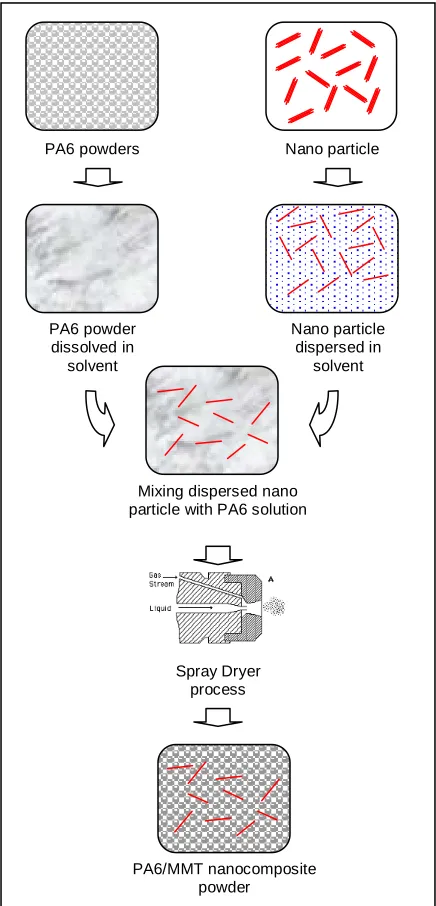
[image:2.595.317.535.221.674.2]The preparation procedure is shown schematically in Figure 2 and aimed to prepare materials with a good dispersion of the additive in the polymer matrix.
Figure 2: Schematic representation of
preparation procedure for PNC, consisting of nano additive particles and PA6 by using
a solution method
Nano particle
Nano particle dispersed in
solvent PA6 powders
PA6 powder dissolved in
solvent
PA6/MMT nanocomposite powder Mixing dispersed nano particle with PA6 solution
The PA6 powder as well as the nano particles were dissolved in formic acid (HCO2H) in separate containers and stirred at room temperature for 3hrs. Then the dispersed nano particles were added the PA6 solution at 5wt% and stirred for another 4hrs. A Labplant model SD05 spray dryer was been used in the production of powder. Spray drying involves the atomization of a liquid feedstock into a spray of droplets and drying of the droplets with hot air in a drying chamber, as shown in Figure 3. The powders obtained from the process were then further dried in an oven at 70oC for another 4hrs. The powder was then ball milled for 2 hrs to break up any agglomerated particles. The preparation finished with a sieving process starts using mesh sizes from 200 µm to 70
[image:3.595.81.286.362.514.2]µm.
Figure 3: Spray dryer machine (Labplant-
SD-05) used in production of powder
2.3 Characterisation
Differential scanning calorimetry (DSC) was performed on a Perking-Elmer DSC 7 under nitrogen purge at a heating and cooling rate of 10oC/min. 10mg of samples were heated from room temperature 30oC to 250oC. Measurement of tensile strength was carried out using a DARTEC tensile machine with 5kN load cell and cross-head movement of 1mm/min. Specimens were fabricated using SLS experimental machine based on ASTM D638 type V standard [16]. TEM (Philips CM200) and SEM (Philips XL30) were used to observe the dispersion of nano additive and analysed the fracture surface morphology of
the processed material. The fracture surfaces of the tensile specimens were investigated to study the fracture behaviour of different composites and the mechanisms of the enhanced mechanical properties.
2.4 SLS processing
[image:3.595.325.530.388.544.2]A CO2 SLS experimental machine, constructed at the University of Leeds [17], with build volume 75mm x 75mm x 100mm has been used to fabricate the test specimen as shown in Figure 4. The test specimens have been fabricated using process parameters of 6 Watt laser power, 500 mm/s scanning speed, 0.6 mm spot size on the bed, 0.1 mm scan spacing and 0.1 mm layer thickness. During processing, the powder chamber was heated to 195oC through heating elements in the piston. Figure 5 shows tensile and density test specimens produced.
Figure 4: CO2 SLS experimental machine
(a) (b)
Figure 5: (a)Tensile and (b) part density test
specimen
PNC powder
3. Results and discussion
3.1 Morphology
Figure 6 shows a general view of the as received PA6 powder as well as the additives. The PA6 powder (Figure 6(a)) has an irregular shape with a rough surface observed on SEM. The additives had all been observed using FEGSEM after dispersion in the surfactant material. The BWH, Figure 6(b), and the MCMO, Figure 6(c), are the layered particles with different characteristics. The BWH has a long strip like ribbon shape whereas the MCMO more looks like a square with the size estimated at less than 100nm.
(a)
[image:4.595.317.533.208.399.2](b) (c)
Figure 6: Morphology images of raw
material: (a) PA6 powder (b) BWH (c) MCMO
3.2 Dispersion of additive in PA6 matrix
The additives were analysed for dispensability in solvent as well as in the PA6 solution. Samples were made from evaporation of the additive suspension in solvent and PA6 solution, and deposited on a carbon TEM grid. The analysis was based on observation of the morphology images using TEM. Bright-field TEM images of the samples, together with the EDX analysis of selected areas, are presented in Figure 7. The dark contrasts seen on the micrographs are the additives particles on the TEM grid. Most obvious differences in the figures are the dispersion and distribution of the additives
either in the form of primary particles or crystallite particles. It can be seen that the solvent has broken the agglomerated particles and reduced the extent of layer stacking of the clay materials. While the individual clay layer is visible, small aggregates can still be observed in some areas.
(a) (b)
Figure 7: (a) BWH (b) MCMO dispersed in
PA6 matrix
The hybrid polymer solutions and additives were successfully spray dried using a mini spray dryer machine. As the SEM images of the spray dried PA6 and PNCs, it appears in general to be spherical with a relatively smooth and closed surface which forms agglomerate particles. This is probably due to the adsorption force of the small particles on the surface. Concentration level of the solution was studied and found to be influenced on particle size and morphology.
[image:4.595.72.294.301.545.2]tension and formed a small drop which would form powders. On the other hand, at high concentration, the viscosity of the solution is also high, and the drop produced is in continuous form which would form fibres as well as powders. Through the observation, the concentration of 30g/litre was found to have good combination with the spray dryer setting to produce powders with average size of 10-40µ m.
(a) Concentration of 100g/litre
(b) Concentration of 50g/litre
(c) Concentration of 30g/litre
Figure 8 Photographic images and SEM
images of sample powder from spray dryer process prepared with different concentration
levels
The particle size distribution of the spray-dried powder was measured using laser diffraction technique, Malvern Mastersizer E. The measured mean size was 30 µm, with some particles at below 1µm, as shown in Figure 9.
Figure 10 shows the TEM images sectioned of the PA6/BWH and PA6/MCMO materials after having been processed by SLS. The dispersion of BWH and MCMO were random across the PA6 matrix suggesting good dispersion was achieved
using the preparation method described in section 2.2.
Figure 9: Particle size measurement
(a) (b)
Figure 10: TEM images of the SLS
processed for (a) PA6/BWH and (b) PA6/MCMO nanocomposites
3.3 Thermal properties
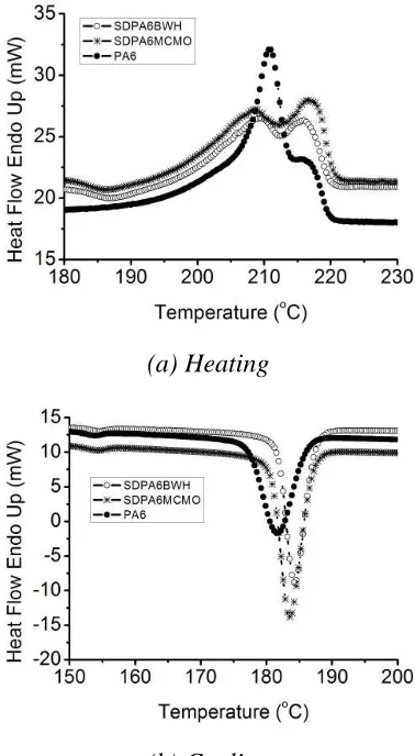
Figure 11 shows DSC results for PNC’s and the unfilled PA6, highlighted at the peaks area during heating and cooling process. During heating, the PA6 and the composites show endotherms with two melting peaks. According to Sesha [19], this double melting phenomenon ascribed due to bimodal crystallite distribution is common to nylons like PA6 and is a characteristic of melts crystallised at a heating rate of 10oC/min. Further, the appearance of dual melting peaks in both the neat PA6 and PNC proves that this is not due to the presence of additives generated in the system under study. The higher temperature peak represents the melting point (Tm) of the α -form crystal of PA6, and the lower temperature peak resulted from imperfect
Particle Diameter (µm.) %
0 10 20
0 10 20 30 40 50 60 70 80 90 100
[image:5.595.349.502.126.284.2] [image:5.595.77.290.235.504.2] [image:5.595.319.534.263.465.2]crystals. Only one exothermic peak temperature (Tc) was observed for each cooling curve between 179oC and 183oC. The addition of clays raised Tc by about 2-4oC, and Tc did not change very much with different clays materials.
(a) Heating
(b) Cooling
Figure 11: Melting and cooling peaks of PA6
and PNC materials
3.4 Part density
The apparent density of the sintered specimens was measured by weighing SLS specimens of approximately 20 x 5 x 2 mm. The average density was obtained from 10 measurements and the results are shown in Table 1. The density of spray dried material was slightly lower than that of the as received PA6 material.
Table 1: SLS part density
Materials Density,ρρρρ
(kg/m3) SD
As received PA6 Spray dried PA6
Spray dried PA6/BWH Spray dried PA6/MCMO
840 811 806 779
1.1 10.5 2.95 5.84
Note: Density for moulded part PA6 material = 1120 kg/m3 [20]
3.5 Tensile properties
Figure 12 shows stress-stroke curves of the PNCs together with the unfilled PA6. The as received PA6 shows a very consistent result with the higher stroke value as compared to the spray-dried material. The spray-dried materials showed low maximum stress values which were identified as the tensile strength properties for the materials.
Figure 12: Stress-stroke curves of the (a) As
received PA6 (b) Spray dried PA6 (c) Spray dried PA6/BWH and (d) Spray dried
PA6/MCMO
[image:6.595.88.277.193.537.2] [image:6.595.321.530.381.542.2]
PA6/BWH and PA6/MCMO nanocomposite materials with 5wt% additives were found to have strengths 50-60% higher on average than that of spray dried PA6 without reinforcement. This suggests that the reinforcement of MMT clays in PA6 has improved its properties. However, it clear that the spray drying process has an adverse effect on the base mechanical properties.
Figure 13: Tensile strength result for the
PNCs and the unfilled PA6.
3.6 Microscopy of tensile fracture surface
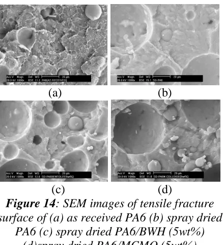
Figure 14 shows the morphology of the tensile fracture surface for PNC and unfilled PA6.
(a) (b)
[image:7.595.97.273.220.352.2](c) (d)
Figure 14: SEM images of tensile fracture
surface of (a) as received PA6 (b) spray dried PA6 (c) spray dried PA6/BWH (5wt%)
(d)spray dried PA6/MCMO (5wt%)
The sintered specimens for the spray dried material contain voids which would act to
reduce density and strength. Most of the voids for the spray dried material are spherical in shape and bigger than those in the as received PA6. This suggests that the cause was trapped gases generated from residual solvent from the spray drying being driven off during laser sintering.
3.7 Hardness test
[image:7.595.316.552.326.435.2]Table 2 shows the hardness test results for the studied materials. The hardness value for spray-dried PA6 and PNCs are lower than that of the as-received PA6. This reduction was thought to be as a result of the porous structure found in the spray-dried material observed in Figure 14.
Table 2: Hardness test
Materials Hardness
(Shore-D) SD
As received PA6 Spray dried PA6
Spray dried PA6/BWH Spray dried PA6/MCMO
77.1 70.3 72.3 70.6
0.9 0.7 1.5 1.7
4. Conclusions
The following conclusions were drawn from this study:
1. PA6/BWH and PA6/MCMO
nanocomposite materials have been successfully prepared by solution blending, followed by spray drying. 2. The TEM observation on SLS processed
PNC materials have shown that good dispersion of the BWH and MCMO clays in PA6 matrix were achieved.
3. SLS fabrication of near-full dense samples for the PNC material was possible.
4. The spray drying process was found to reduce the tensile strength of the PA6 material.
5. References:
[1] N. Calder, Rapid manufacturing of functional materials. In proceeding of
[image:7.595.75.294.470.710.2]the TCT2001 Conference, Manchester, 26-27 Sept. 2001
[2] Materialise, [Accessed 25/10/07]. Available from World Wide Web:
http://www.materialise.com/prototyping solutions/laser_ENG.html
[3] Nelson, J. C., Xue, S., Barlow, J. W., Beaman, J. J., Marcus, H. L., & Bourell, D. L., “Model of the selective laser sintering of bisphenol-A
polycarbonate”, Industrial &
Engineering Chemistry Research,
32(10), (1993), 2305-2317.
[4] P. Dickens, R. Hague, R. Harris, N. Hopkinson, C. Tuck, T. Wohlers, in: T.Wohlers (Ed.), Wohlers Report 2005, Wohlers Associates Inc., 2005, ISBN 13-978-0-470-01613-8
[5] N. Hopkinson, P. Dickens, Rapid prototyping for direct manufacture, Rapid prototyping J.; 7,4; 2001, pg. 197.
[6] N. Hopkinson, P. Dickens, Analysis of rapid manufacturing-using layer manufacturing processes for production, Proc. Instn. Engrs Vol. 217 part C
[7] Kruth, J. P., Leu, M. C., & Nakagawa, T. (1998). Progress in additive manufacturing and rapid prototyping.
CIRP Annals - Manufacturing
Technology, 47(2), 525-540.
[8] H. Huang, X. Huang, Y.F. Wang, Y.H. Zhang, Microstructure changes of a polypropylene/montmorillonite nanocomposite in a single screw extruder, 2003, Journal of Materials Science Letters, 22(21), 1547-1549. [9] J. Kim, T.S. Creasy, Selective laser
sintering characteristics of nylon 6/clay-reinforced nanocomposite, J. Polymer Testing. 2004.01.014
[10] J.H.Koo, S.Lao, W.Ho, K.Nguen, J.Cheng, L.Pilato, G.Wissler, M.Ervin, Polyamide nanocomposite for SLS, in proc. 2006 SFF symposium.
[11] J.Cheng, S.Loo, K.Nguyen, W.Ho, S.Cummings, J.Koo, SLS processing of
nylon 11 nanocomposite, in proc. 2005 SFF symposium.
[12] NPL, Nano-Composites Long-term Mechanical Properties. [Accessed 15/12/04]. Available from World Wide Web:
http://nanomaterials.npl.co.uk/composi tes/nano_comp2.html
[13] Vollath, D., & Szabo, D. V. (2004). Synthesis and Properties of
Nanocomposites. Advanced
Engineering Materials, 6(3), 117-127.
[14] Goodfellow, Material datasheet for PA6, 2006.
[15] Southern Clay product Inc. Material datasheet for Bentolite WH and Mineral Colloide MO, 2004
[16] ASTM D638-03 Standard Test Method for Tensile Properties of Plastics. ASTM International
[17] C. Hauser, Selective laser sintering of stainless steel powder, PhD Thesis, 2003, University of Leeds.
[18] K. Masters (1975) Spray drying handbook, 5th edition , John wiley & Sons, New York
[19] A.V. Sesha, T. Inoue, K.Yonetake, K. Koyama (2001) Thermal behaviour of poly(acryloyloxybenzoic acid)/nylon 6 blends, Polymer, v 42, n 24, 9859-62 [20] Matweb, Overview of materials for
Nylon 6, Unreinforced [Accessed 25/10/07]. Available from World Wide Web:
![Figure 1: Schematic diagram of selective laser sintering [3]](https://thumb-us.123doks.com/thumbv2/123dok_us/8782932.905246/1.595.321.513.582.714/figure-schematic-diagram-selective-laser-sintering.webp)