Systems Reference Library
IBM 1401 Symbolic Programming Systems: SPS-1 and SPS-2
Specifications and Operating Procedures
This manual provides programmers with the informa-tion necessary to code a 1401 program in SPS language and assemble a machine-language object-program. It is assumed that the programmer has a basic knowledge of 1401 machine language programming.
It describes symbolic programming principles and concepts and gives detailed speCifications of the 1401 Symbolic Programming Systems, SPS 1 and SPS 2.
Operating instructions for processing the SPS source program are enumerated. The SPS processor program can assemble a machine language program on configu-rations of the 1401 Data Processing System equipped with a 1402 Card Read-Punch.
A sample program is included for the convenience of the beginning SPS programmer. Input and output forms, a block diagram of the program procedure, the symbolic program, and SPS output listings of the sym-bolic and machine-language programs are shown.
Preface
This manual describes the language specifications and operating procedures for the IBM 1401 Symbolic Pro-gramming Systems SPS-1 and SPS-2.
This manual is designed for programmers who know the input, output, and processing characteristics, as well as the basic functions and operations of the IBM
1401 Data Processing system.
The language is presented in a special format that:
• describes generally each type of SPS statement
• describes specifically the construction of the state-ment
• describes generally the processing and assembly functions
• shows an example of how each statement can be used in a program.
The operating procedures are presented in detail with descriptions of deck assemblies, error notes, etc.
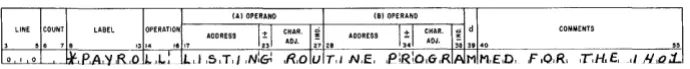
A sample problem shows a simple payroll listing including input and O:Itput documents, the SPS source program, and the output from assembly.
This SRL publication, C24-1480, obsoletes the IBM 1401 Data
Processing System Bulletins: IDM 1401 Symbolic Programming
System: Preliminary Specifications, J24-0200, and IDM 1401
Symbolic Programming Systems: SPS-1 and SPS-2, J24-1412.
Copies of this and other IDM publications can be obtained through IDM Branch Offices.
Contents
Introduction ... "... 5
IBM 1401 Symbolic Programming System 6 Advantages of IBM 1401 SPS ... 6
Programming with SPS ... 7
Symbolic Language ... ... ... ... ... 7
Processor Program ... 7
Information Requirements ... "... 7
Coding Sheet ... ... ... ... ... 7
Address Assignment .. ... ... 12
Declarative Operations Imperative Operations Special Mnemonic Operation Codes ... . Processor Control Operations ... .. 13 17 17 19 SPS Processor Operations ... 21
Pre-Process Listing Routine ... 21
Processor Assembly Program ... 22
Processor Output ... ... ... ... ... 26
Post-Process Listing Routine ... 28
Condensing Routine ... ... 29
IBM 1401 SPS Sample Program ... 30
'''ith the increasing capability of data processing sys-tems, programming in the actual machine language of a system has become more complex. Not only does machine-language coding require memorization of a great many numeric and alphabetic codes but J also the length and intricate design of programs written in machine language make them prone to logical and clerical errors.
Also, the problem of correcting errors in an actual machine-language program is intensified because of the difficulty in tracing the steps of a machine-language program to include corrections and relocate the prob-lem in storage.
Symbolic programming, the use of mnemonic char-acters to write a program, has been developed to facilitate computer programming. When mnemonic in-structions are used, data may be referred to in terms which are logical to the layman, as well as to the experienced programmer. Another advantage of sym-bolic programming is that the checking of each pro-gram may be performed by a person other than the programmer.
In a symbolic system, a routine to add current withholding tax to total miscellaneous deductions, sub-tract the total from gross pay, and store the amount as net pay might look like this:
OPERATION CODE
ZA A ZA
S
OPERANDS
CUHWTX ACCUM TOTMDN ACCUM
GROSS NETPAY
ACCUM NETPAY
The first instruction in this routine sets to zero a machine storage area, which is arbitrarily labeled
ACCUM. It then adds the current withholding tax (an
area called CURWTX) into this area. The next
instruc-tion, total miscellaneous deductions (TOTMDN), is added
to the contents of ACCUM, which is CURWTX.
Then a storage location, labeled NETPAY, is set to
zero, and gross pay (CROSS) is added into it. In the last
step the contents of ACCUM (CURWTX
+
TOTMDN) issubtracted from the contents of NETPAY (CROSS). This
puts (CROSS-CURWTX-TOTMDN) in a suitably labeled
loca-tion (NETPAY), to which the programmer may refer
later in the program.
Once the data and working areas have been defined and labeled, it is easier to follow the logic of this
Symbolic Programming Systems
short routine written in symbolic form than to compre-hend the same routine written in machine language, which might look like this:
OPERA TION CODE
?
A
?
:£
OPERANDS
060 S93 045 S93 050 A95 S93 A95
A program written in symbolic programming lan-guage (the source program) requires translation into an actual machine-language program (the object pro-gram) before a computer can execute it. This trans-lation is done by a machine-language program called a processor. In general, the translation is "one-for-one." That is, for each instruction written in symbolic form, one machine-language instruction is produced.
The processor, sometimes called an assembly system, generally utilizes the machine for which the symbolic program is written. It analyzes all symbolic entries and converts them to actual machine operating data and instructions, establishing specified relationship be-tween them.
As an additional feature, as:sembly programs also indicate various types of errors such as coding, out-of-sequence cards, etc. Symbolic programming saves time and simplifies coding. Because actual machine ad-dresses of data and instructions are assigned auto-matically by the processor, the programmer need not concern himself with this detail. He can, however, refer to these addresses symbolically.
Once there is an agreement on label terminology, subroutines (short programs or routines common to a number of programs) may be easily incorporated in any program, and a major program may be written in inde-pendent parts with no loss of efficiency in the final program. Corrections and modifications of program in-structions also entail no reassignment of addresses by the programmer. Finally, the automatic assignment of addresses makes programs and subroutines readily relocatable, i.e., they can be placed in varying machine locations as desired.
Because of the advantages in symbolic programming for the IBM 1401 Data Processing System, IBM has
IBM 1401 Symbolic Programming System
The IBM 1401 basic Symbolic Programming System,
SPS-1, operates on the 1400-character machine with the 1402 Card Read-Punch and the 1403 Printer, but it can assemble programs for any object machine con-figuration up to 4000 positions of storage. An expanded Symbolic Programming System, SPS-2, can assemble programs for any size object machine (1,400 to 16,000 positions of storage), but requires assembly on a 1401 system that has at least 4,000 storage positions and the 1402 Card Read-Punch, and the 1403 Printer. The general description and operating procedure of both systems are the same; however, any characteristics that apply only to the expanded programming system, be-cause of its larger machine storage requirements, will be noted throughout the manual.
Advantages
of
IBM 1401 SPS
Some significant advantages of the IBM 1401 Symbolic
Programming System are:
• Simplifies program writing and organization. For ex-ample, it is easier to write and refer to an instruction such as S WHTAX GROSS (Subtract Withholding Tax
from Gross) than to look up the addresses of with-holding tax and gross for an instruction like ~ 599618. • Provides continuity for group programming efforts. Upon agreement of labeling terminology, program routines can be written independently and efficiently and can be combined for assembling because ad-dresses are automatically assigned by the processor. • Simplifies program adjustment. If programs require partial revision, only the affected routines need to be rewritten.
• Detects coding errors. Illegal operation codes, in-valid addresses, sequence errors, etc., are detected by the SPS listing routine before the program is actu-ally assembled.
• Facilitates program testing. Explanatory comments may be listed next to program instructions.
Prograrnming
with
SPS
Effective programming in IBM 1401 requires a knowl-edge of the methods of programming in machine lan-guage. Before the programmer begins to code his pro-gram in symbolic language, (as when writing in actual machine language) he draws a block diagram of the procedure the program must take to accomplish a desired end result. From this block diagram he must determine which constants and work areas are needed.
Constants are fixed data, such as a standard FICA
LIMIT calculation. '-'10rk areas are locations within core
storage where the data can be manipulated, such as input and output areas, accumulator fields, etc. Then he writes the instructions for the program.
Symbolic Language
The symbolic language includes a standard set of
mnemonics. These mnemonics are standardized
abbre-viations for operation code descriptions, and are usu-ally easier to remember than the machine-language codes. For example:
DESCRIPTION MNEMONIC
Multiply M
Clear 'VIr ord Mark CW
MACHINE LANGUAGE CODE
(jjt
g
A list of mnemonic operation codes is shown in Fig-ure 38. Also included as part of the symbolic language are standard methods for defining areas and entering constants, comments, etc.
By using the symbolic language, the programmer can control the locations of record and work areas if he so chooses, or he can leave this job to the processor program ..
Processor Program
A standard deck of cards furnished by IBM contains
the processor program that produces the ob;ect pro-gram (actual machine-language propro-gram) from the source program (symbolic language program). The
SPS processor, also called an assembly program, as-sembles the object program from information given in the source program statements. The object program is then punched in one-instruction-per-card format. The punched output deck is then used to load the assem-bled machine-language program into core storage prior to its execution.
Information Requirements
The information that the processor program requires to assemble the object program is divided into three major categories:
Area Definition (Declarative Operations) Instructions (Imperative Operations)
Processor Controls (Process Control Operations)
Area Definition
These statements assign sections of storage space for work areas. The assigned areas will be used by the object program and may contain the data to be proc-essed and/or the constants required to execute the object program. Area definition statements in most cases do not result in instructions to be executed as part of the object program. However, the processor program does produce for these statements cards con-taining constants and their assigned machine addresses. These constants cards are loaded with the object pro-gram each time the propro-gram i.s used.
Instructions
Most of the statements on the program sheet are the instructions for the data processing job to be per-formed. These statements are translated by the proc-essor program into their machine-language equivalents in the object program.
Processor Controls
These statements are special signals to the processor program. They allow the programmer to adjust certain portions of the assembly process. These statements are never executed in the object program.
These three types of information ate presented to the processor program in the form of SPS statements written originally on a special Symbolic Program Cod-ing Sheet.
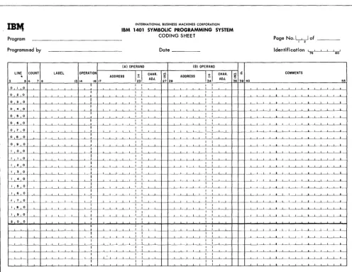
Coding Sheet
The IBM 1401 Symbolic Program Coding Sheet (Fig-ure 1) is fixed-form. A special field is provided for each item of information required by the processor. Each statement is written on a separate line.
Before assembly, each line of the coding sheet is key punched into a card. These cards make up the source program deck which is the input to the proc-essor program.
To facilitate key punching, IBM makes available a special card, electroplate C55369, for use with the 1401 SPS. This card is also used to contain the object pro-gram as it is punched as output from the assembly process.
The function of each portion of the coding sheet is explained in the following paragraphs.
Page Number (Columns 1 and 2)
This two-character entry provides sequencing for cod-ing sheets. Only numerical characters may be used. Standard collating sequence for the IBM 1401 should be followed when sequencing pages.
Line Number (Columns 3-5)
A three-character line number sequences entries on each coding sheet. The first 20 lines are prenumbered 010-200. The third position is punched zero, the lowest number in the collating sequence. The six unnumbered lines at the bottom of each sheet can be used to con-tinue line numbering or to make insertions between en-tries elsewhere on the sheet. The units position of the line number indicates the sequence of inserts. Any nu-merical character can be used, but standard collating sequence should be used. For example, if an insert is to be made between lines 020 and 030, it could be numbered 021. Line numbers do not necessarily have to be consecutive, but the deck should be in collating sequence, for sorting purposes.
The programmer should note that insertions can af-fect address adjustment. An insertion might make it necessary to change the adjustment factor in the oper-and of one or more entries. All insertions should be placed in their proper sequence in the source program deck before assembly.
Count Field (Columns 6 and 7)
The number of characters the assembled actual machine instruction or defined area is to contain is punched into this field. The processor uses this number to allo-cate storage locations for data and instructions. For example, if the count field of an area definition state-ment contains a 6, six storage locations will be allo-cated for that area. The processor will also use this number to assign an address for the area. See Address Assignment.
Because the processor can determine the length of an instruction from the information presented in the statement, the programmer can leave the count field blank for instruction entries. The processor will de-velop and punch the count in the count field of the object program deck in any case. For instructions, the processor will override any punching in the count field.
Label Field (Columns 8-13)
The label is a symbol or descriptive term selected by the programmer to identify the specific area or instruc-tion represented by the source program statement in which the label appears. The label may then be used elsewhere in the program, i.e., in an operand of another source program statement, to refer to the area or in-struction which it identifies.
It is advantageous to devise a label that suggests the meaning of the area or instruction, so that the source program can be easily interpreted by anyone con-cerned with the program. For example:
TYPE OF STATEMENT MEANING LABEL
Area definition Withholding Tax WHTAX
Instruction Update UPDATE
Labels are used only with area definition and in-struction statements. Remember that core storage is allocated, and an address is assigned for all instructions and most area definitions. If the statement is labeled, the assigned address is known as the "equivalent ad-dress" of the label. The processor maintains during assembly a table of labels and their equivalent ad-dresses. When a label appears in the operand of a statement, its equivalent address may be found and substituted for the label in the assembled statement. The equivalent address of the label of an instruction is made equal to the leftmost, or high-order, core-storage position of those positions allocated to the instruction. The equivalent address of the label of a defined area or constant is made equal to the right-most, or low-order, core-storage position of those posi-tions allocated to the area or constant.
No two labels in the source program may be iden-tical.
The label is punched beginning in column 8 of the label field. It can be as many as six alphamerical char-acters in length and the first, or leftmost, character must be alphabetic. No actual machine addresses or special characters should be used for this purpose. Blanks must not appear within a label.
Operation (Columns 14-16)
This field contains the operation code for the state-ment. Area-definition and processor control statements always have mnemonic operation codes. Instruction statements can have either mnemonic or actual opera-tion codes. If the mnemonic op code is used, it is writ-ten and punched beginning in column 14 of the opera-tion field. Actual op codes are punched in column 16.
Operands (Columns 17-27 and 28-38)
In the (A) and (B) operand fields are placed the programmer's designations of:
data to be operated upon, or the input-output units to be operated.
2. For area definition statements: the constant being defined:, the address at which the constant is to be stored, or the address or input-output unit which is to be the equivalent of the label.
3. For processor control operations: the address which is to be used with the particular control of the proc-essor being invoked by the programmer at that point in the program.
It is evident, then, that each entry in the operand fields serves one of the following purposes:
1. It designates a core-storage address. 2. It designates an input-output unit. 3. It provides the constants being defined.
Core-Storcuge Address Operands
These are designated by using the Address, Character Adjustment, and Indexing portions of the operand field.
There are four types of core-storage address operands: Symbolic, Actual, Asterisk, and blank.
SYMBOLIC ADDRESSES
A symbolic address can be composed of as many as six letters or digits (no special characters), but the first (high-order) character must be a letter. It refers to an instruction or area definition statement in the source program whose label is identical to it. For example, if
ENTRY A is used as the label for an instruction in the
source program, ENTRYA can be used as the symbolic
operand of another instruction which references it such
as B ENTRYA (Branch to the instruction whose label is
ENTRYA).
Each symbol used must have a corresponding label because the processor substitutes the address assigned to the label wherever the symbol appears in the oper-and field of another source program statement. If character adjustment or indexing is associated with the
IBJ.1
INTERNATIONAL BUSINESS MACHINES CORPORATIONProgram
LINE
.
GOUNT LABELII Il 7 6
0 1 0
o 4 0
o II 0 ---1
o 6 0
OPERATION
13 14 16 17
IBM 1401 SYMBOLIC PROGRAMMING SYSTEM
CODING SHEET
Date
(A) OPERAND (8) OPERAND
ADDRESS ± ADDRESS ± ~ d
23 34
CHAR. ADJ.
38 39 40
Page No.
W
of-Identification , I eo'
76
COMMENTS
55
_l_-'---'----L-L- L~-'---'----'----+__\---L--1---"---'---'--'---'---'---'---_l__+__+--'---.L--.l.---...L...L_LI --'---'--'I---II__L_L---'---'---'---J
I I
i-L-~I~~--'-~_l_~
---L---'---'---'---'---'---__'___-f-_+__+--'--..L-l--L~--'----'---.L--'---''--'--L---'---L--L_j
I
...L.---L--L.-+--'---'---'--t---1I--'----'--'----~--:--'---'--+--+--t--L-J _..J_~ L' __,___, - ' - ' --L....L.-'----'----'---'----L..-I
.L--'---'---'---L-+~--"----'--~..L..-'--...L..--'--t__If_+--'---L-~ -,-' --,---,---, ~I,---,,--,--,---, I
--,---'-,--,---,-1 --'---'---'--f--t--+-->-..L--L-L-l ___ -'---.L--.L__'__''__'--'-___'_____L__L_j
I
.L--+--"---C--I--'---'----'-~~-'---'---'--t__Ij---!_.J--'--'---'---'-_-'--...L.._-'--+-+--j---! __ .J. ___ L - L - l ___ -'----'---'---'---'---''--'--'--'---'---I
_L-~L __ ~---'-____L_..L_--,--~I ~~-'---+-~_ I
I I
--'---t---"---C--I--'---'---L---'---L-_I _ _ ---L--'-~-+-'--'--'---'---'---'---'---'---'--+-+--I----'---' __ J __ ...L-..l I
[image:9.620.73.570.317.700.2]I
symbolic address, the processor will modify the ad-dress assigned to the label accordingly.
The programmer may write a symbolic address in a statement that precedes the labeled statement in the source program, because the processor does not assign addresses until all source program statements have been examined and the entire label table has been created.
ACTUAL ADDRESSES
In SPS-1 an actual address is a four-digit number written and punched beginning in column 17 of the A-operand field or in column 28 of the B-operand field.
In SPS-2 actual addresses can be either four or five digits, depending upon machine size, and are written and punched beginning in column 17 of the A-operand field or in column 28 of the B-operand field.
Figure 2 shows the use of one symbolic and one actual address in the source program.
Figure 2. SPS Instruction with Symbolic and Actual Addresses
ASTERISK ADDRESSES
An asterisk address is the character "*,, left-justified in the address field. Like symbolic addresses, it has a core-storage equivalent, but this equivalent address is simply the rightmost, or low-order, position in the instruction or data field defined by the statement.
Figure 3 shows an SPS statement with an asterisk address. In this example, the instruction was assigned the address 0906 during assembly. Because the instruc-tion is seven characters in length, the low-order posi-tion of the instrucposi-tion is 0912. The processor substitutes this address in the A-operand of the statement shown in Figure 3 and assembles it: M 912285. Thus, the actual machine-language instruction will appear in core . storage as shown in Figure 4 after the object program has been loaded.
Figure 3. SPS Statement with an Asterisk Address
Character
Core-Storage Location
M
-906 9
907
1 2 2 8
908 909 910 911
Figure 4. Assembled Instruction in Core Storage 5
912
BLANK ADDRESSES
Blank addresses are valid in instructions where no operand is needed. (See Imperative Operations.) Input-Output Operands
The three-character addresses of tape units, disk stor-age units, and other input-output or storstor-age units re-quiring special addresses are written left-justified in the A -operand field.
For example, the three-character address of tape unit 1 is the A-operand of the SPS statement shown in Figure 5.
Constant Operands
A constant operand is valid only in an area-definition statement which contains a constant to be loaded with the assembled object program. The constant should be written and punched exactly as it is to be loaded and stored. It must begin at column 24 and may extend to column 55.
Figure 6 shows a constant operand. The field to be defined is labeled FICALT. The constant is 480000.
Character Adjustment (Columns 23-26 and 34-37). It is
possible to reduce the number of labels required in a source program by using a character-adjustment factor with an actual, asterisk or symbolic address in the operand field of an SPS source program state-ment.
The adjustment factor is written and punched as a plus or minus (& or -) in the -t- column (23 or 34) and the number of positions of adjustment (as many as 3 digits) right-justified in the Char. Adj. field (columns 24-27 or 35-38).
During the assembly of the machine-language object program entry, this adjustment factor is added to or subtracted from the actual address assigned to the label by the processor. Thus, one label can
Figure 5. Addressing a Tape Unit in an SPS Statement
Figure 6. Constant Operand
serve as a reference point for more than one ad-dress. 1;'or example, if ENTRYA is the label for an
instruction which precedes the instruction, which could be called ENTRYB, the programmer can use
ENTRYA as the reference point for ENTRYB.
If the instruction whose label is ENTRYA is 7
char-acters long, the symbolic entry operand ENTRYA +007
will produce an actual address equal to the address that would have been created if ENTRYB had been
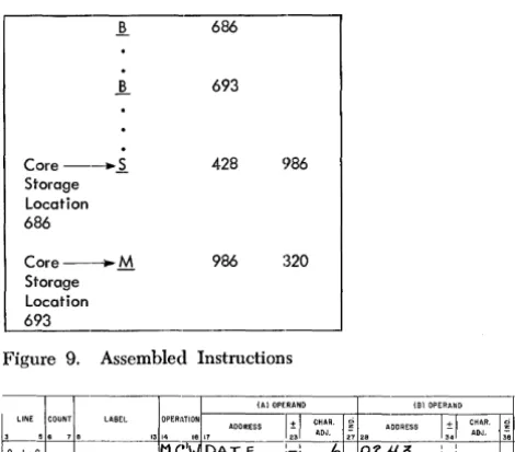
used as the label for the second instruction. Figure 7 shows a section of a source program in which two separate labels are used. Figure 8 shows the same section in which one label is used. Both sections produce the same result in the object program (Fig-ure 9).
Figure 10 shows how character adjustment can be used to address a location within a labeled field.
DATE is a twelve-character constant. The character
adjusted operand will cause only the first six digits of the date (i. e., DEC 28, rather than DEC 28, 1961) to be moved to 0243.
Because the number of labels used in a source pro-gram can have a significant effect on the amount of time required to assemble an SPS program, character
Figure 8. One Label Used with Character Adjustment
].. 686
~ 693
Core--~ Storage Location
686
Core--..M Storage Location
693
428
986 986
:320
Figure 9. Assembled Instructions
Figure 10" Character Adjustment Used in Addressing
a Location within a Field
adjustment is especially recommended in source pro-grams which require a considerable amount of label-ing. The number of labels that can be processed in one pass of SPS assembly depends upon the size of the processing 140l. Details are given in the operat-ing section of this publication.
NOTE: The programmer must be careful when
making insertions in a source program where char-acter adjustment has been used. The insertion could necessitate changing the adjustment factor in one or more SPS statements. This same caution also ap-plies to patching.
Indexing (Columns 27 and 38). If the
advanced-programming feature is available in the machine that executes the object program (object machine), the programmer may indicate that an actual, sym-bolic, or asterisk address is to be indexed. He does this by writing the SPS index code in the index col-umn of an SPS statement.
The index codes are 1, 2, and 3. A code 1 in an index column specifies that the address in the same operand field is to be indexed by the contents of index location
i
(core-storage locations 087 -089) when the object program is executed. A code 2 specifies index location 2 (core-storage locations 092-094) and a code 3 specifies index location 3 (core-storage locations 097-099).When the processor program encounters an in-dexed operand, it puts tag bits over the tens position of the assembled three-character machine address as follows:
INDEX CODE
1 2
3
TAG BITS TENS POSI1'ION
A-bit B-bit
A and B-bits
ZoNE PUNCH
o
11
12
For example, the source program statement shown in Figure 11 specifies that the B-operand is to be modified by the contents of index location l. The processor will assemble an instruction that will cause
TOTAMT to be moved to a field whose address is
equal to 596 plus the contents of index location at program execution time. If index location 1 contains 100 when the instruction is executed, TOTAMT will
be moved to 696. Assume that the equivalent ad-dress of TOTAMT is 428. The machine-language
in-struction produced by the SPS processor program will be: M 428 5Z6.
[image:11.617.70.312.358.456.2] [image:11.617.72.307.485.692.2]NOTE: Character adjustment and indexing entries
are valid only with core-storage address operands, and then only when the address field of the operand is actual, symbolic, or asterisk. These entries are not valid with input-output unit operands or constant operands, nor are they valid when a core-storage address operand designates the address at which a defined area or constant is to be stored.
d-Character (Column 39)
Some 1401 instructions require a special modifier to the operation code called a d-character. It is a single alphabetic, numerical, or special character written and punched in column 39. The d-characters are always written in machine-language and are simply trans-ferred by the processor to the d-character position of the assembled machine-language instruction.
Comments (Columns 40-55)
This field is reserved for programmer's notes or com-ments about a particular entry. A source program that contains a complete set of comments can be more easily understood and traced by all persons concerned with a given program. The comments have no effect on the object program as it is assembled or executed. Columns 56-75 of source program cards must be left blank, or incorrect processing will occur.
COMMENTS CARD
To provide the programmer with the ability to insert more extensive descriptive information in the program listing than is possible by using the comments field on a program entry card, a comments card may be included in the source program deck.
Comments cards will not be assembled nor will they affect the assembling procedure. When encountered by the processor, they will be reproduced unaltered in the SPS output deck, and will be bypassed when the object program is being loaded.
The Programmer:
l. Indicates with an asterisk in the first position of the label field (column 8) that the card is a comments card.
2. May write the comment beginning at any position (columns 9-55). Comments extending beyond posi-tion 55 may cause an error during processing.
The Processor: Reproduces (unaltered) the comment
in proper sequence in the program listing.
Figure 12. Typical Entry on an SPS Comments Card
12
Example: In the sample program, the entry in Figure
12 is a comments card entry.
Identification (Columns 76-80)
This field may contain any 1401 characters which the programmer selects to identify the program.
Address Assignment
To assign addresses to instruction and area-definition entries, the 1401 SPS processor uses a "storage assign-ment counter." This counter stands at 333 at the be-ginning of assembly (333 is the first available storage location beyond the standard read punch and print areas). However, the programmer can force the proc-essor to begin assigning addresses elsewhere. See
Origin.
During the first pass of assembly, the processor allo-cates storage for constants, work areas, and instruc-tions. The amount of storage needed for each such entry is determined by the number in the count field. This number is simply added to the storage-address assignment-counter to develop addresses.
If the statement being processed has a label, the processor transfers it and its equivalent address to the label table.
During the second pass the processor converts these addresses to three-character machine addresses and stores them in the object program statements where corresponding symbols appeared in the operand fields of the source program statements. If character adjust-ment and indexing are specified, addresses are modi-fied before they are stored.
Addresses for asterisk operands in instructions are determined by the address assigned to the low-order position of the instruction. This information is part of the loading data and is thus available when instruc-tions are assembled for the object program deck.
NOTE: Actual addresses in area-definition statements
do not affect the storage assignment counter and the count field in these statements is ignored. However, labels and the actual addresses associated with them are stored in the label table. The programmer must be careful that the locations specified in these statements are not the same locations that will be allocated by the processor to other statements in the source pro-gram. Otherwise, the processor will re-allocate them, and part of the object program will be destroyed at program load time,
[image:12.613.53.398.663.697.2]Declarative Operations
(Area-Definition Statements)
The IBM 1401 SPS provides four different declarative
operations for reserving work areas and constants.
MNEMONJ[C Op CODE PURPOSE
DCW Define Constant with Word Mark
DC Define Constant (no Word Mark)
DS Define Symbol
DSA Define Symbol Address
DCW - Define Constant With Word Mark
General Description: A DCW statement causes a
con-stant to be loaded into a core-storage area and a word mark to be set in the high-order position of this area at program load time.
The Programmer:
1. writes DCW in the operation field.
2. writes in the count field the number of core-storage positions needed to store the constant or work area. 3. writes a symbol in the label field if he wishes to refer later to the address of the field where the con-stant is stored.
4. writes the address of the area in which the constant is to be stored. If the programmer wishes to let the processor assign the address, he simply writes an asterisk (*) in column 17. Otherwise, he writes an actual address beginning in column 17. In any case the address will refer to the low-order (units) posi-tion of the defined area.
5. writes the constant beginning in column 24 of the coding sheet. The constant may extend to the end of the comments field (column 55). Thus, the maxi-mum size of a constant is 32 core-storage positions. 6. may write a comment in columns 40-55 if these
posi-tions are outside the range of the constant itself as specified in the count field.
NOTE: In SPS-l, comments in DC and DCW statements
are never listed. DCW and DC operands may not have
character adjustment or indexing.
NUMERICAL CONSTANTS
A plus or minus sign can precede a numerical constant. A plus sign causes AB-bits to be placed over the units position of the constant; a minus sign causes a B-bit to be put there. The plus or minus sign i.s written and punched in column 23. If no plus or minus sign appears in column 23, the constant is stored at program load time as an unsigned field.
Figure 13. Numerical Constant (Signed)
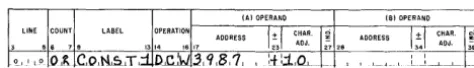
Example: Figure 13 shows the numerical constant
+
10 defined in a DCW statement. The programmerhas selected core-storage positions 3986 and 3987 as the location for the constant. It will be stored I? Figure 14 shows an unsigned numerical constant (designed for use as a work area). In this example seven zeros are loaded to initialize the work area to
QOOOOOO. The asterisk indicates that the processor is
to assign the address of the constant.
Figure 14. Work Area Defined by a DCW Statement
ALPHAMERICAL CONSTANTS
An alphamerical constant can consist of any valid 1401 characters. Alphamerical constants are always un-signed.
Example: Figure 15 shows the alphamerical constant
DATE defined by a DCW statement. The programmer
has selected 0499 as the address of the constant. Be-cause DATE is now equivalent to address 0499, the
constant can be referred to as either DATE or 0499.
The constant will be loaded as DEC 28, 1961. Figure 16 shows the alphamerical constant EDTWDI
defined in a DCW statement. The constant 1,bb,bbO.bb
will appear in core storage as a field whose units posi-tion is determined by the processor.
Figure 15. Alphamerical Constant
Figure 16. Edit Control Word Defined by a DCW Statement
BLANK CONSTANTS
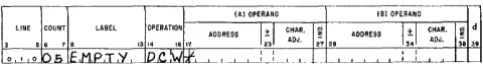
[image:13.620.327.564.61.95.2] [image:13.620.324.564.252.283.2] [image:13.620.328.564.515.549.2]Figure 17. Blank Constant
Example: Figure 17 shows a blank constant .hbbbb
coded in a Dew statement and labeled EMPTY. The
processor assigns the address.
The Processor:
1. allocates a field in core storage to store the constant. The number in the count field determines the num-ber of positions allocated.
2. adds the number in the count field to the number that was standing in the storage assignment counter
if there is an
*
in column 17. The result becomes the address of the constant. This address is made equivalent to the label, and the two are stored in the label table.If the programmer has specified the address, this address is equated to the lahel before it is stored in the label table. The count field is examined and used to create the loading data for the Dew card, but the storage assignment counter is undisturbed. 3. substitutes the equivalent addresses of labels in the operands of symbolic program statements which have corresponding symbolic addresses during as-sembly of the object program.
4. produces a card, as part of the object program, con-taining the data defined, with a sign if required, and instructions to load the constant into core stor-age with a word mark in the high-order position. This card is loaded with the object program, and the constant is stored exactly as the Dew source program statement defined it. For blank constants, the area is cleared of all existing word marks except the high-order word mark for the Dew constant.
DC - Define Constant (No Word Mark)
General Description: This statement is the same as a
Dew statement except that the processor does not set a word mark in the high-order position of the con-stant.
NOTE: The storage area to which the constant is to
be moved should be cleared of word marks.
DS - Define Symbol
General Description: DS statements cause the processor
to assign equivalent addresses to labels or to assign storage for work areas. DS statements differ from Dew and DC statements in that no data is loaded into
the defined area at program load time. ADs-defined area is unaffected during the loading of the object program. Data, word marks, instructions, previously
14
put in the area, remain unaltered. Thus, if DS state-ments are used only to define areas, using a clear storage routine before loading the program is recom-mended.
Some DS statements affect the storage assignment counter. These can be used to bypass areas needed for independent routines (instructions or data not in-cluded in the source program being assembled) or for storing constants for which the programmer has selected the actual storage locations.
The Programmer:
1. writes DS in the operation field.
2. writes a symbol in the label field if he wishes to refer symbolically to the low-order position of the area.
3. writes the address of the area.
If the processor is to assign the address, he writes an asterisk in column 17 and writes a number in the count field to indicate the size of the area.
If the programmer wants to equate the label to an actual address or I/O unit operand, he writes the address or I/O operand beginning in column 17. In this case no storage will be allocated by the processor, so the count field is left blank.
NOTE: DS statements cannot be character-adjusted
or indexed.
The Processor:
1. adds the number in the count field to the storage assignment counter and equates the resulting ad-dress to the label if one appears in the DS statement
if there is an asterisk in column 17. If an asterisk or I/O unit operand appears in the DS statement, the processor equates the label to the operand. 2. substitutes the equivalent addresses of labels in the
operands of symbolic program statements which have corresponding symbolic addresses during the assembly of the object program.
3. leaves the defined area unaltered during object program loading.
Examples: Figure 18 shows a DS statement with an
asterisk address. This 8-position area which can be referred to as INPUTA will be assigned an actual
ad-dress which will be the low-order core-storage posi-tion occupied by the area when the program has been loaded.
Figure 19 shows a DS statement used to equate a label to an actual core-storage address. (This type of DS statement is used for assembly only, and does not require any storage space in the object machine. Thus,
[image:14.617.55.297.58.90.2] [image:14.617.311.553.667.698.2]Figure 19. DS Statement Equating a Symbolic Address to an Actual Address
it is very useful in creating symbols for addresses that must be referenced often in the source program.) An input card contains current gross in card columns 40-44. When the card is read into 1401 core-storage, cur-rent gross will be in positions 0040-0044. The program-mer wants to refer to current gross as CURGRO so that
[image:15.615.65.308.69.119.2]he does not have to remember the actual address (0044). The statement shown in Figure 19 allows him to use CURGRO as a symbolic address for 0044.
Figure 20 shows how a DS statement can label a tape
unit. The programmer can now use TAPE1 instead of
[image:15.615.65.308.467.500.2] [image:15.615.70.307.536.574.2] [image:15.615.329.566.665.704.2]% VI in the A-operand of a magnetic tape instruction. Figure 21 shows how a DS statement can bypass 20
positions of core storage. The constants of the storage assignment counter will be increased by 20 when the processor encounters this statement. The processor will not re··allocate these 20 storage positions. However, an actual address in another area-definition statement or an instruction patch card can cause data to be loaded into them. For example, if the counter con-tained 0936 before this statement was processed, it would contain 0956 afterward. The DCW statement shown in Figure 21 would cause CONST2 (1875) to be loaded into storage positions 0953-0956 at object pro-gram load time.
Figure 20.
Figure 21.
Assigning a Label to a Tape Unit
Advancing the Storage Assignment Counter and Using the Bypassed Area
DSA - De1fine Symbol Address
General Description: A DSA statement causes the
three-character machine address which the processor has assigned to a label to be stored as a constant when the object program is loaded. This three-character address is called an address constant. Address
con-stants are used to modify addresses during the exe-cution of an object program.
The Programmer:
1. writes DSA in the operation field.
2. may leave the count field blank because an address constant is automatically assigned three core-storage positions by the processor.
3. may write a symbol in the label field if he wishes to refer later to the address of the address constant. 4. writes the address of the area in which the address constant is to be stored. If the programmer wishes to let the processor assign the address, he writes an asterisk (*) in column 17. In any case, the address will refer to t he units position of the three-character address constant.
5. writes the symbol whose equivalent address is to be the address constant beginning in column 28 of the (B) operand field. This operand may have char-acter adjustment and indexing.
The Processor:
1. allocates a three-position field in core storage in which will be stored the address constant at pro-gram-load time.
2. adds three to the number that was standing in the core storage assignment counter if there is an
*
in column 17. The result becomes the address of the address constant. This address is made equiva-lent to the label, and the two are stored in the label table. If the programmer has specified the address, this address is equated to the label before it is stored in the label table. The storage assignment counter is not affected when an actual address is used.3. looks up in the label table, the equivalent address of the symbol in the B-operand and uses this address as the address constant.
4. produces a DSA card containing the address
con-stant and instructions to load this concon-stant into core storage with a word mark in the high-order position of the three-character field"
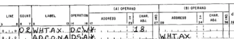
Examples: Figure 22 shows how a DSA statement can
develop an address constant. In another part of his source program, the programmer has used the
sym-bol WHTAX. During assembly, the processor will
as-sign a three-character machine address to WHTAX,
but the programmer does not know what that address will be. Yet for an address modification operation he needs this machine address (stored as a constant)
so that he can write an instruction that will move it into the A- or B-operand of another instruction at program execution time. The programmer wishes
to refer to the address of the address constant as aADCONA.
For the example shown in Figure 22 assume that the storage assignment counter is standing at 584 when the DCW statement is encountered.
The processor will assign 586 as the address of WHTAX and 589 as the address of ADCONA. These two constants will appear in core storage as shown in Figure 23, after the object program has been loaded. Figure 24 shows another section of the source pro-gram that uses ADCONA.
Assume that the equivalent address of INSTR is 829 and WORKAR has an equivalent address of 763. The processor will assemble these two instructions. M 589832 A 000 763. When the first instruction is exe-cuted in the object program, the second instruction will be modified to A 586 763. When the second instruction is executed, WHTAX (18) will be moved to WORKAR.
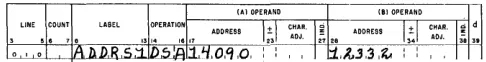
Figure 25 shows a DSA statement with an actual ad-dress in the B-operand. In this case the programmer knows the actual address he wants to store as an ad-dress constant, but he does not want to bother to translate the actual address to a three-character ma-chine address. The DSA statement causes the mama-chine address of 12332 (;J.3B) to be stored as an address constant in core-storage locations 14088-14090. The programmer can refer to the address constant as 14090 or as ADDRSl.
Character
Core-Storage Location
WXTAX
~
585
8
586
Figure 23. Constants in Core Storage
ADCONA
~ 8 6
587 588 589
Figure 24. Instructions U sing an Address Constant
Figure 25. DSA Statement with Actual B-address
[image:16.613.51.292.466.522.2] [image:16.613.49.292.634.665.2]Imperative Operations (Instructions)
General Description: SPS imperative operatIOns are
direct commands to the object machine to act upon data, constants, auxiliary devices, or other instruc-tions. Thus, they are the symbolic statements for the instructions to be executed in the object program. Most of the statements in the source program will be imperative instructions. The programmer must be careful to write instructions that use only the fea-tures and devices that are included in the machine that will execute his program.
The Programmer:
l. writes the operation code for the instruction in the operation field. Mnemonic op codes are written left-justified in the operation field. Actual op codes are written in column 16. (Also, see Coding Sheet). 2. leaves the count field blank if he so desires. 3. writes a symbol in the label field if the instruction
is an entry point for a branch instruction elsewhere in the program or, if he wishes to make other refer-ence to it. This label is assigned an address equal to the core-storage location occupied by the opera-tion code of the associated instrucopera-tion at program load time. Thus, the programmer can use this label as a symbolic address in another SPS instruction. 4. writes in the (A) and (B) operand fields, core-storage
addresses or I/O Unit Addresses.
Core Storage Addresses. These are symbolic, actual, asterisk, or blank addresses representing the A/lor B addresses of actual machine-language instructions. Symbolic, actual, or asterisk operands may have char-acter adjustment and indexing.
NOTE: Blank operands are valid:
a. in an instruction that does not require an operand (such as a read instruction).
b. in instructions in which useful A- or B-addresses are supplied by the chaining method such as Mew
FIELDA ]l"IELDB Mew Mew.
If an instruction is to have addresses stored by other instructions, the operand or operands affected must not be left blank. Zeros are recommended as shown in the DSA example.
Input/Output Unit-Addresses. An I/O unit operand is valid only in the A-operand field of an SPS state-ment. It is the three-character address of an auxiliary device such as tape unit (% Ux).
5. writes the d-character in column 39 if one is needed for the instruction. The d-character is always writ-ten in actual machine language.
NOTE: Blank is not a significant d-character except in
the If-Character-Equal instruction. A
Branch-If-Bit-Equal (BBE) instruction with a blank d-character will be assembled as a seven-character instruction.
The Processor:
l. substitutes the actual machine-language operation code in place of the mnemonic operation code and transfers it to the operation-code position of the assembled machine-language inst~uction. Actual op codes are simply transferred as they are written in an SPS instruction statement.
2. counts the number of characters that will appear in the assembled instruction and adds this number to the number that was standing in the storage-assignment counter.
3. allocates a field in core storage that will be occupied by the assembled machine-language instruction. 4. stores the label (if one appears in the label field) and
its equivalent address in the label table. Remember that an equivalent address assigned to a label in an instruction statement is the address assigned to the position occupied by the operation code when the instruction is loaded in the object machine.
5. looks up in the label table the equivalent addresses of symbols used in the operand fields of an instruc-tion and inserts them in the actual machine-language instructions.
Converts actual addresses to three-character ma-chine addresses and transfers them to the mama-chine- machine-language instruction.
Replaces asterisk addresses with the address oc-cupied by the low-order position of the instruction in object-core storage, and transfers them to the machine-language instruction.
Transfers an input-output unit operand to the A-address portion of the machine-language instruction. 6. produces a card, as part of the object program, which contains the machine-language instruction, and the information necessary to load it with a word mark in the op-code position.
NOTE: All instruction operations: Arithmetic, Data
Control, Logic Control, and System Control are ex-plained in the IBM 1401 Data Processing System
Ref-erence Manual, Form A24-140:3. Operations requiring
special features ,(noted by an asterisk in Figure 38) are also described in this manual. The programmer should thoroughly review the operation code functions before attempting to program in SPS.
Special
Mnemonic Operation Codes
MA - Modify Address
The IBM 1401 MA operation code facilitates address
arithmetic for systems equipped with more than 4,000 positions of core storage. It causes the data defined by the A- and B-operands to be added together and the result to be stored in the B-field at program execution time. Thus, a new address is developed in the B-field. If the MA statement has an (A) operand only, the
three-character machine address is added to itself and the result is stored in the A-field at program execution time.
The SPS-1 processor will accept the MA mnemonic
operation code and assemble it as an A (Add) com-mand, even though the modify-address feature is not available on 1400, 2000, and 4000 systems.
The SPS-2 processor will assemble the MA operation
code as a modify-address command if the object ma-chine has more than 4,000 storage positions. If there are 4,000 core-storage positions or fewer, it will assem-ble an A (Add) as in SPS-l.
Example: Figure 26 shows an SPS-MA statement coded
to double the address assigned to ADCONA. After MA
instruction is executed in the object program, the field whose address is ADCONA will contain +50, the
machine address equivalent of 1050 (0525
+
0525).Figure 26. MA Statement with A-address Only
LU - Load Unit
The LU mnemonic is convenient to use for instructions
that address magnetic tape units, RAMAC®, and other input-output devices. The processor produces a LOAD
(L) instruction that will transfer data and word marks from the unit to the field whose address appears in the (B) operand. Figure 27 shows an LU statement that
will produce an instruction that will read a tape rec-ord (with wrec-ord marks) into core storage at program execution time.
MU - Move Unit
The MU mnemonic has the same function as LU,
ex-cept that word marks are not transferred by the
MOVE (M) operation it produces.
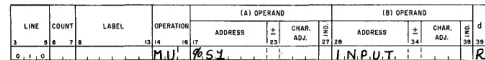
Figure 28 shows an MU statement that will produce
an instruction to read information into storage from an IBM 1412 Magnetic Character Reader.
Figure 27. LU Statement
[image:18.613.306.549.388.418.2]Processolr Control Oper,ations
The IBM 1401 Symbolic Programming System provides
four processor control operations. These following commands, which are never executed in the object program, control the assembly process:
OPERATION CODE
CTL
ORC
EX
END
Cll - Control
PURPOSE Control Origin Execute End
General Description: The control card is placed at the
beginning of the source deck, so that the SPS proc-essor is able to distinguish the storage sizes of the processing machine (machine which assembles the object program), and the object machine (the one that executes the assembled object program).
In SPS-1, the CTL card also signifies the availability
of the punch-release feature to the processing ma-chine. The punch-release feature is not used in SPS-2.
The Programmer:
1. writes the mnemonic code (CTL) in the operation
field.
2. indicates in column 17 the size of the processor ma-chine. This will determine the maximum number of labels that can be processed per iteration. See Labels.
SPS-1 Codes
COLUMN 17 CODE
1
2
3
STORAGE POSITION
1400 2000 4000
If a number other than one of these code digits is specified, if the card column is blank, or if the CTL
card is omitted from the source program deck, the processor assumes a 1400-character machine.
SPS-2 Codes
COLUMN CODE
3 4
5
6
STORAGE POSITION 4,000 8,000 12,000 16,000
If a number other than one of these code digits is specified, if the card column is blank, or if the CTL
card is omitted from the source program deck, the processor assumes a 4000-character machine. 3. indicates in column 18 the size of the object
ma-chine. This will indicate to the processor how much
storage space will have to be cleared at load time for the assembled program.
For both processors, SPS-l and -2 the machine codes are the same as previously listed. If column 18 is blank, the processor assumes the object machine size is the same as the processor machine. Also, in both SPS-1 and -2, the processor assumes the object machine to have 1400-character storage if there is an illegal code punched in column 18.
4. if he is using SPS-1, the programmer indicates in column 19 whether the punch release feature is available to the processor. This feature is used by pass one of the processor.
COLUMN 19 CODE
1
blank
MEANING
Punch Release Available Punch Release Not Available
If any other digit is punched, the processor as-sumes no punch release feature.
The Processor interprets the machine size and feature
codes and processes the source program accordingly.
ORG - Origin
General Description: An ORC statement causes the
processor's storage assignment counter to assign ad-dresses beginning at a particular location specified by the programmer. If it is entered as the first card of the source program, an ORC card can cause the initial assignment of addresses to be at a location other than 333. An ORC statement may be includcd at any desired point in the source program. This will cause the counter to be reset and cause all future entries to be assigned addresses beginning at the particular location designated by the programmer. Character adjustment and indexing are not valid in an ORC statement.
The Programmer:
1. writes ORC in the operation Held.
2. writes the actual machine address at which assign-ment is to begin left-justified in the (A) operand. 3. inserts the card in the desired place in the program.
The Processor:
1. assigns addresses to instructions, constants, and work areas, beginning at the address specified in the (A) operand.
2. causes the storage assignment counter to assign sub-sequent addresses beginning at the address written in the (A) operand if an ORG statement is
encoun-tered at any point in the source program.
Figure 29. onc Statement
first entry is an instruction, the op-code position of that instruction will be 900; if the first entry is a seven-character Dew, it will be assigned address 906, etc.
EX - Execute
General Description: During the loading of the
assem-bled machine-language program, the programmer may wish to discontinue the loading process tem-porarily to execute a portion of the program just loaded. This can be accomplished through the use of an EX statement placed in the source program.
Using an execute command, the programmer can divide his program into several program sections if his total program exceeds the limit of available stor-age capacity.
The Programmer:
1. writes EX mnemonic operation code in the opera-tion field.
2. writes a symbolic or actual address left-justified in the (A) operand. This indicates to the processor which instruction is to be executed after the loading process has been stopped. A blank or asterisk oper-and should not be used.
3. to continue the loading process after the desired portion of the program has been executed, the pro-grammer must provide as the last instruction of the portion executed an instruction to read a card and branch to location 0056. This location contains an instruction to load the rest of the program.
If the read area will be altered by the execution of the portion of the program, the programmer must provide, as the last instruction of the portion exe-cuted, instructions to clear the read area, and set word marks in locations 0024, 0056, 0063, 0067, as well as the read and branch operation as previously explained.
l.ABEL
(AI OPERAND (81 OPERAND
+ CHAR.
;3 ADJ. 27 29
~ d
, I
L--..L....-l..-.L...L..-..t---f---.L
L J I L I , _I.. _I I
_1-_L--.l_-1~ .. _j_.L ... 1 ______ ~ __ J ___ ..L __ _
o Of GXECul'UJ'
,--+-L-L-++ _L_ .. L __ L._L---L-_L ___ .... __ .1 _1._
~~___L~.L_!..._~-L...L...
.~~~ _ _1 __ • .L _ _
,ok.'ZL-L:{_LL
_, ! , , ! : :_-L L J l I _I I L J _ l L-...L...L-L .. __ ..L .. L _ .. L . .. _L __ .1. _
The Processor assembles a branch instruction. This
in-struction is not part of the object program, but it causes the loading operation to halt at the appro-priate time. The branch instruction is then executed.
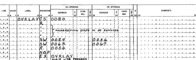
Example: It is sometimes desirable to execute the
ini-tial, or housekeeping, steps that are not necessary to continuous running or restarting of the program so that they may be then destroyed and new instruction or constants loaded over them. This routine, called
an overlay, is executed as directed by an EX
state-ment.
In the routine shown in Figure 30 the housekeep-ing instructions will be executed, the read area will be re-initialized, and the rest of the program will be loaded.
NOTE: The Nap instruction insures that a word mark follows the R0056 instruction.
The condensing routine output is compatible with this format. The routine, upon encountering an EX card, punches the cards necessary to re-initialize the read area for the condensed routine.
END - End
General Description: An END statement is a signal to
the processor that the last card in the source program has been processed. If the programmer specifies in the (A) operand the actual or symbolic address at which the object program is to begin execution, an END statement will produce an instruction that will start program execution immediately after loading. If the (A) operand is blank, the 1401 will halt when the last insh'uction has been loaded.
The Programmer:
1. writes END in the operation field.
2. may write a symbolic blank, or actual machine ad-dress (left-justified) in the (A) operand. An asterisk operand is not permissible.
The Processor clears the read area "(positions 001-080)
of core storage and assembles an instruction that branches to the address specified in the (A) operand after loading is completed.
_ L __ J ___ L_L_-1 __ !_-' ____ L-L--+-I---+--'---'--L-L--'---L-L--L. __ L_-L-L-L...-L_--L_...l_
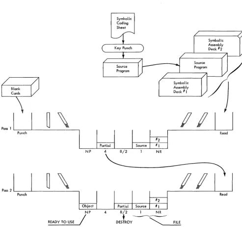
[image:20.617.58.296.68.109.2] [image:20.617.63.399.588.692.2]The IBM 1401 Symbolic Programming System is com-posed of five separate programs:
• Pre-Process Listing Routine • Processor - Pass One ~
Processor Assembly Program • Processor - Pass Two
• Post-Process Listing Routine • Condensing Routine
The processor program listings and a table of ad-dress displays for 1401 halts is found in the IBM 1401
Program Library publication: Symbolic Programming Systems, SPS-1 and SPS-2 (File Number 2.0.003).
Pre-Process
Listing
RoutilleThe SPS :Pre-Processor Listing Routine .rnakes it pos-sible for the programmer to detect many coding or keypunching errors in the program deck before as-sembly.
The Operator:
1. puts sense switch A on.
2. places decks to be loaded behind the routine in the read hopper.
3. resets the 1401 and loads the program. The Routine:
1. restores the printer carriage. All input cards to the program are selected to stacker 1.
2. prints the card image and messages into eleven fields on the printed page in the following format:
Page Number (Card Columns 1-2). Zeros are
sup-pressed in this listing.
Line Number (Columns 3-5). Line number is printed
as is.
Count (Columns 6-7). Zeros are suppressed in listing.
The routine determines the count for instructions and DSA cards.
Label (Columns 8-13). The routine prints only the
labels to be used by the processor. Thus, a label on an ORC card would not be listed.
Operation (Columns 14-16). This symbolic operation
code is reprinted.
SPS Processor Operations
(A) Operand (Columns 17-27);; (B) Operand (Columns
28-38). These are reprinted from the card except that there is a space between character adjustment and the indexing indicator. Only the digit position of the index appears.
d-Character (Column 39). This actual
machine-lan-guage modifier is reprinted as is.
Location. Each time an ORC card is sensed, and at the
end of the object program, the highest storage ad-dress used is printed in the location column. It is not printed for the first origin card unless it has been preceded by fields whose addresses are assigned by the processor.
SPS-l Error Notes
In the pre-process listing, the processor may indicate in code, one of five errors under this field:
Err 1. Page-Line Sequence. Page or line number out
of sequence.
Err 2. Count. Indicates illegal count for DC and DCW
cards. If the count is greater than 32, only columns 23-55 are printed.
Err 3. Illegal Op Code. Indicates illegal mnemonic
operation code. A CTL card in any other position than the first in the source deck will be processed as an instruction card and thus give this error.
Err 4. Illegal Operand. Indicates illegal operand. An
instruction card containing a non-blank address with the high-order position blank, will cause this error. For DCW, DC, DSA, and DS statements, this error is indicated when the (A) operand is blank, symbolic, or % (except for DS).
Err 5. Column 56 Not Blank. Indicates column 56 is
not blank. NOTE: Information in columns 56-74 can cause improper processing when assembling.
SPS-2 Error Notes
Because of increased storage available to the routine, additional error-checking features are included. The complete error legend is:
Err 1. Page-Line Sequence. Indicates that a page or
Err 2. Count. Indicates the count for a DC or DCW is
greater than 32 or less than 1, or that the program-mer has not indicated the count for a DC, DCW, or DS
statement.
Err 3. Label. Indicates that the first character in a label
is blank, numeric, or a special character. Also recog-nizes a DS card without a label whose (A) operand
is not an asterisk (*). This type of card is meaning-less to the processor and is noted as a potential error.
Err 4. Illegal Op Code. Indicates illegal mnemonic
operation code or a blank operation code field. A
CTL card in any other position than the first in the
source deck will be processed as an instruction card and thus give an illegal op code error. (These cards will be created as DCW'S if there is a count.)
Err 5. Illegal (A) Operand indicates:
l. An instruction with a (B) operand but not (A) op-erand.
2. A blank or symbolic (A) operand for a DCW, DC, DS,
or DSA statement.
3. A non-numeric address for an ORG statement.
4. An asterisk address for an EX or END statement.
5. In a general operand error: a. The indexing is not 1, 2, or 3.
b. C