Design and Simulation of Slotted Rectangular Microstrip
Patch Antenna
Nivedita Girase
Research ScholarTIT(Excellence)
Rahul Tiwari
TIT (Excellence)Archana Sharma
TIT(Excellence)Hema Singh
TIT(Excellence)ABSTRACT
This paper presents the design of compact slotted rectangular microstrip patch antenna for operates 5 GHz. The proposed antenna is designed on RT duroid substrate with dielectric constant of 2.2 and fed with 50 ohms microstrip line. Further DGS (Defected Ground Structure) technique is used to increase the gain of the antenna. Bandwidth is enhancing by introducing the slot in the rectangular patch antenna. The characteristics of the proposed antenna have been studied with the help of HFSS (High Frequency Structure Simulator) software. HFSS is a high performance full wave electromagnetic (EM) field simulator. Ansoft HFSS employs the Finite Element Method (FEM). The design targets the frequency band (5.180 – 5.825 GHz) being used in various wireless communication systems, such as satellite communication, radio altimeters etc. The final antenna produced 720MHz bandwidth,1.11 VSWR and 7.27dB gain at frequency 5.39 GHz.
General Terms
In this paper slotting has to be done to enhance the bandwidth.
Keywords
Slotting of the patch technique, DGS , C band
1.
INTRODUCTION
Antenna is basically a guiding transitional that is used for radiating or receiving radio waves. The first well-known antenna experiment was conducted by the Heinrich Rudolf Hertz in 1886, which consisted of the dipole antenna is also called the Hertz (dipole) antenna. Then Guglielmo Marconi developed and commercialized wireless technology by introducing a radiotelegraph system, where he used Monopole antennas (near quarter-wavelength).manuscripts [1].
The concept of microstrip antenna was first proposed by Deschamps in 1953 [2]. However, practical implementation of this concept of microstrip antennas was not achieved until late 1970s, by Munson and Howell [3]. A conventional microstrip antenna in general consists of a conducting patch printed grounded microwave substrate with ground plane below, as shown in figure 1. Microstrip antennas have attractive features of low profile, light weight, easy fabrication, and conformability to mounting hosts. However, microstrip antennas inherently have a narrow bandwidth, and bandwidth enhancement is usually demanded for practical applications. To overcome these techniques a number to techniques have been proposed in literature. One such technique to increase the bandwidth of the antenna is to modify the ground plane, referred to as Defective Ground Structure (DGS).
Figure 1. Microstrip Antenna
A Microstrip device literally means a sandwich of two parallel conducting layers separated by single thin dielectric substrate. The lower conductor is called ground plane & the upper conductor is a simple resonant circular/rectangular Patch. The metallic patch (usually Cu or Au) may take many geometrics viz. rectangular, circular, triangular, elliptical, helical, ring etc. The Microstrip patch antenna is commonly excited using a microstrip edge feed or a coaxial probe. The canonical forms of the microstrip antenna are the rectangular and circular patch MSAs. The rectangular patch antenna in is fed using a microstrip edge feed and the circular patch antenna is fed using a coaxial probe.
IEEE 802.11b/g/n products operate in the worldwide free 2.4GHz ISM band. Besides these other wireless technologies like Bluetooth, ZigBee and several other proprietary technologies also operate in the 2.4GHz band. These large numbers of technologies crowding the same frequency band lead to interference problem. To remove stress on this band, now days IT communication is permitted to 2.4GHz band and M2M communication is being shifted to 5GHz ISM band (5.180 – 5.825GHz). Also the IEEE 802.11a radio utilizes the 5GHz frequency band. Hence more and more applications now days target this unlicensed 5GHz band. Thus this paper work targets this band.
2.
ANTENNATHEORY AND DESIGN
Ansys HFSS is for designed the proposed antenna for 5GHz ISM band. First a simple rectangular microstrip antenna (RMSA) is designed using RT duroid as substrate. It has dielectric constant of 2.2 and a loss tangent of 0.0009. Table I below gives the formulas for the calculating the width and length of the patch. The width (W) and length (L) of the patch are approximated to 20.8mm and 16mm respectively. Figure 2 shows the designed RMSA.
20 achieve the increase in BW of the antenna. Figure 5 shows the
[image:2.595.318.545.73.318.2]final proposed antenna.
Table 1: Antenna Design Parameters
Dielectric substrate and Loss Tangent εr=2.2,
tanδ=0.0009 Substrate height
h = 1.6 mm
Substrate width W = 21.9 mm
Effective Dielectric Constant εeff =2.403
Length Extension ∆L=0.59 mm
Effective Length Leff = 17.91 mm
Substrate Length L = 16.32 mm
Mathematical Calculation
Step 1: Calculation of the Width (W ):
W= 21.8mm
Step 2: Calculation of Effective dielectric constant ( εeff):
εreff = 2.037
Step 3: Calculation of the Effective length ( Leff ):
Leff= 17.91mm
Step 4:Calculation of the length extension (ΔL ) :
ΔL = 0.59mm
Step 5:Calculation of actual length of patch ( L ):
L = 16.32mm
Step 6:Calculation of the ground plane dimensions ( Lg and Wg ):
Lg = 6h+L = 6(1.6) + 18.8 = 25.92mm
Wg = 6h+W = 6(1.6) + 21.8 =31.4mm
Step 7: Calculation of Microstrip Feed Line Width (w’)
0
60
8
4
n
reff
h
W
Z
W
h
, W/h ≥1
0 2 1 1 1 1
' 1.4953
119.9 2 1 2 4
r r
n n
r r
Z
H
l l
1
'
exp
'
1
1.993
8
4 exp
'
w
H
h
H
w’
= 1.2 mm
Figure 2.Front view of simple rectangular microstrip antenna (RMSA)
[image:2.595.59.278.117.279.2]L = 16mm and W = 21.8mm
[image:2.595.337.522.330.500.2]Figure 3. Side view of rectangular patch antenna
Figure 4. Rectangular Microstrip Antenna with a slot. Ls = -14mm and Ws = 2
1 2
2
r
fo c W
2 1
12 1 2
1 2
1
W h r
r
reff
reff fo
c Leff
2
8 . 0 258
. 0
264 . 0 3
. 0 412
. 0
h W reff
h W reff
h L
L Leff
[image:2.595.335.521.534.697.2]Figure 5. Slotted Rectangular Microstrip Antenna Ls1=Ls2= -14mm and Ws1=10mm, Ws2 = 2mm
3.
RESULTS
Figure 6 below shows the S11 graph of the simple rectangular microstrip antenna (RMSA) shown in figure 2. From this it can be seen that the resonant frequency is 5.41 GHz with BW of 120 MHz. Figure 7 shows the S11 graph for the antenna with slots. The resonant frequency is 5.63 GHz with BW of 230 MHz. Figure 8 above shows the S11 graph slotted rectangular microstrip patch antenna (proposed antenna) with increased BW of 720 MHz.
[image:3.595.78.256.75.241.2]It is clear from the results that in simple rectangular microstrip patch antenna bandwidth is less after inserting the single slot bandwidth increased and finally in proposed antenna design bandwidth becomes 720 MHz because of slotting technique.
Figure 6. S11 for Simple Rectangular Microstrip Antenna
Figure 7. S11 for Rectangular Microstrip Antenna with slot
[image:3.595.320.539.75.451.2]Ls = -14mm and Ws = 2
Figure 8. S11 for slotted rectangular microstrip antenna
Ls1=Ls2= -14mm and Ws1=10mm , Ws2 = 2mm
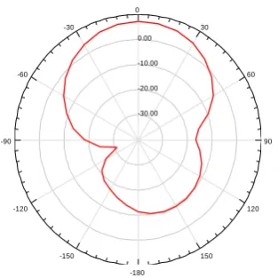
Figure 9 below shows the VSWR graph of the proposed antenna. The obtained VSWR is 1.115. Figure 10 and 11 shows the 3D polar and radiation pattern of the proposed antenna design.
Figure 9. VSWR for proposed antenna.
1.00 2.00 3.00 4.00 5.00 6.00 7.00
Freq [GHz]
-25.00 -20.00 -15.00 -10.00 -5.00 0.00
S
1
1
d
B
HFSSModel1
XY Plot 1 ANSOFT
m1 m2
m3 Name X Y
m1 5.4094 -10.8494 m2 5.6242 -10.6949 m3 5.5168 -23.1964
2.00 2.50 3.00 3.50 4.00 4.50 5.00 5.50 6.00 Freq [GHz]
-35.00 -30.00 -25.00 -20.00 -15.00 -10.00 -5.00 0.00
S
1
1
(d
B
)
HFSSModel1
XY Plot 1 ANSOFT
m1 m2
m3 Name X Y
m1 5.5168 -9.9447 m2 5.7584 -9.5684 m3 5.6242 -33.5097
1.00 2.00 3.00 4.00 5.00 6.00 7.00 Freq [GHz]
-25.00 -20.00 -15.00 -10.00 -5.00 0.00
S
1
1
d
B
HFSSModel1
XY Plot 1 ANSOFT
m1 m2
m3 Name X Y
m1 5.0604 -9.9018 m2 5.7852 -9.8694 m3 5.4631 -21.0780
1.00 2.00 3.00 4.00 5.00 6.00 7.00 Freq [GHz]
0.00 2.00 4.00 6.00 8.00 10.00 12.00 14.00 16.00 18.00 20.00
V
S
W
R
HFSSModel1
XY Plot 2 ANSOFT
m1
[image:3.595.59.272.440.599.2] [image:3.595.321.520.506.664.2]22
Figure 10. 3D radiation pattern for proposed antenna
Figure 11. Radiation Pattern for proposed antenna
Figure shows radiation pattern of slotted rectangular microstrip patch antenna. It shows main lobe and back lobe of radiation.
4.
COMPARISON OF RESULTS
[image:4.595.59.277.470.566.2]Table 2 below shows the comparison of results for the all the designed antennas. In this table we easily find out that bandwidth get affected after inserting the slot.
Table 2: Comparison of simulated results.
Antenna
Resonant Freq (GHz)
VSWR Gain
(dB)
BW (MHz)
RMSA 5.41 1.133 6.48 120
RMSA
with slot 5.62 1.104 6.46 230 Proposed
antenna 5.39 1.115 7.27 720
From the comparison table it is clear that in first simple rectangular microstrip patch antenna gain is 6.48dB and bandwidth is 120 MHz. After that single slot inserted in the patch of the antenna then results obtained which gain 6.46 dB bandwidth is 230 MHz. Gain is not affected but bandwidth get affected. Finally in Proposed antenna (Slotted Microstrip Antenna) again slot of particular width and length inserted and in the results gain as well as bandwidth get affected gain obtained 7.27 dB and bandwidth 720 MHz.
4.
CONCLUSION
The analysis of designed microstrip patch antenna was performed by HFSS (High Frequency Structure Simulator) software.A compact slotted microstrip patch antenna has been designed for C-band applications communication systems.
It is concluded from the result that in first simple rectangular microstrip patch antenna the bandwidth and gain obtained are 120 MHz and 6.48dB respectively.
In second design with slot bandwidth and gain obtained are 230 MHz and 6.46dB respectively. And finally in proposed antenna design bandwidth and gain obtained are 720 MHz and 7.27 dB respectively. All the simulations result shows that in proposed antenna bandwidth and gain are improved at frequency 5.39 GHz. The proposed antenna is suitable for satellite communication, RADAR application, Missiles systems needs very light weight antenna which can be easily attached with the systems and not make the system bulky. These requirements are main factors to the development of the rectangular microstrip patch antenna.
5.
ACKNOWLEDGMENTS
It gives me immense pleasure to express my deepest sense of gratitude and sincere thanks to Rahul Tiwari, Assistant Professor, EC Department for his valuable guidance encouragement and help for this work.
I am also very thankful to Prof. Hema Singh HOD of EC department and Dr. Archana Sharma , for theire valuable suggestions and guidance in my work.
6.
ACKNOWLEDGMENTS
It gives me immense pleasure to express my deepest sense of gratitude and sincere thanks to Rahul Tiwari, Assistant Professor, EC Department for his valuable guidance encouragement and help for this work.
I am also very thankful to Prof. Hema Singh, HOD,EC Department and Dr. Archana Sharma, for their valuable suggestions and guidance in my work.
7.
REFERENCES
[1] Constantine A. Balanis, “Antenna Theory Analysis and Design”, Wiley & Sons, INC., Publications.
[2] Girish Kumar and K.P.Ray, “Broadband Microstrip Antennas”, Artech House Boston • London, ISBN 1-58053-244-6.
[3] Munson, R. E., "Conformal Microstrip Antennas and Microstrip Phased Arrays",IEEE Trans. Antennas Propagation, Vol. AP-22, 1974, pp. 74–78.
[4] Vivekananda Lanka Subrahmanya, “Pattern Analysis of The Rectangular Microstrip Patch Antenna”, 30 ECTS, Thesis No.: 4/2009 MSc. Electrical Engineering – Communication & Signal Processing.
[5] Dinesh Yadav, “L – slotted rectangular microstrip patch antenna”, 2011 International Conference on Communication Systems and Network Technologies.
[6] Punit Shantilal Nakar, "Design of a compact Microstrip Patch Antenna for use in Wireless/Cellular Devices”, Florida State University. Electronic Theses,Treatises an Dissertations. Paper 2790.
[7] S. Bhunia, “Effects of Slot Loading on Microstrip Patch Antennas” ,International Journal of Wired and Wireless Communications Vol.1, Issue 1, October, 2012
[8] Punit Shantilal Nakar, “Compact and Broadband Microstrip Antennas”,. Kin-Lu Wong Copyrightc 2002 John Wiley & Sons, Inc. ISBNs: 0-471-41717-3 (Hardback); 0-471-22111-2 (Electronic).
-30.00 -20.00 -10.00 0.00
90 60 30 0
-30
-60
-90
-120
-150
-180
150 120
HFSSModel1
Radiation Pattern 2 ANSOFT
[9] Jimmy Gautam and N. Jayanthi, “Design of Stacked Miniaturized Slotted Antenna with Enhanced Bandwidth for WiMAX Application” 2014 International Conference on Signal Processing and Integrated Networks (SPIN).
[10]Ahmed Khidre, Kai-Fong Lee, Fan Yang, and Atef Z. Elsherbeni ,“Circular Polarization Reconfigurable Wideband E-ShapedPatch Antenna for Wireless applications”, IEEE transactions on antennas and propagation, vol. 61, no. 2, February 2013.
[11]Shiqiang Fu, Qinggong Kong, Shaojun Fang, and Zhongbao Wang, “Broadband Circularly Polarized for L-Band Satellite System Application”, IEEE antennas and wireless propagation letters, vol. 13, 2014.
[12]Atser A. Roy, “Enhancing the Bandwidth of a Microstrip Patch Antenna using Slots Shaped Patch”, e-ISSN : 2320-0847 p-ISSN : 2320-0936 Volume-02.
[13]A.-A Kalteh, “A Novel Microstrip-Fed UWB Circular SlotAntenna with 5-GHz Band-NotchCharacteristics”, 978-1-4244-1827-5/08/$25.00 ©2008 IEEE.
[14]Bimal Garg, Rahul Tiwari, Ashish Kumar and Sunil Kumar Thakur, “Design of Broadband Rectangular Microstrip Patch Antenna Inset 'L' Shaped Feed with Rectangular 'L' Slots in Ground Plane,” International Journal of Computer Applications Volume 29 Number 1(ISBN: 978-93-80864-72-0) 1-4, September 2011. DOI No. 10.5120/3532-4818Published by Foundation of Computer Science, New York, USA.
[15]Rahul Tiwari and Seema Verma, “Design Slotted Patch Antenna on Layer 1.6mm”, International Journal of
Computer Applications Volume 85 Number 19 (ISBN: 973-93-80879-79-1) 1-4, January 2014. DOI No. 10.5120/15091-8035 Published by Foundation of Computer Science, New York, USA.
[16]Rahul Tiwari and Seema Verma, “Inverted L Slot Wideband Rectangular Microstrip Patch Antenna”, International Journal of Advanced Technology and Engineering Research Volume 4, Issue 1, Page No. -27-32, Jan. 2014.
[17]Rahul Tiwari, Preeti Agrawal, Sunil Kumar Tripathi and Richa Sikarwar, “Improving Bandwidth In RMPA Using ‘U’ Shaped Slotted”, International Journal of Advanced Technology and Engineering Research Volume 2, Issue 4, Page No. 211-214, July 2012.
[18]Bimal Garg, Rahul Tiwari, Ashish Kumar and Tilak Chitrance, “Design of Factored ‘X’ Shaped Metamaterial Structure for Enhancement of Patch Antenna Gain,” Presented at IEEE International Conference on CSNT-2011 held on 3-5 June, CSNT-2011 at SMVDU, Katra, Jammu, and Organized by ‘MIR-LAB’ Society Page(s): 232 – 235, E-ISBN :978-0-7695-4437-3,Print ISBN:978-1-4577-0543-4,INSPEC Accession Number:12139368,
Digital Object Identifier
:10.1109/CSNT.2011.57,available on IEEE Xplore.
[19]Rahul Tiwari, Seema Verma, “Proposed A Compact Multiband And Broadband Rectangular Microstrip Patch Antenna For C-Band And X-Band,” International Journal of Computers & Technology Volume 13, No.3, Page No. 4293-4301 April 2014.