Cooperative Communication Simulation using TCP
H.Srikanth Kamath
Assistant Proferssor E&C Dept.
Manipal Institute of Technology, Manipal India
Mohammad Sheikh Ali
Student in the American University of Beirut Lebanon
Beirut
ABSTRACT
Demand for wireless communication has increased rapidly. Almost everywhere there is a wireless device (phones, laptops, etc...) that need to communicate with other mobile devices in their region or to connect to an internet access point, and they need to exchange data especially via internet. As a result, the need of better performance wireless networks has increased to provide people higher-quality wireless communication service. For all these reasons and other reasons researchers are developing new techniques that serve higher-quality wireless networks. One of the most attractive approaches is cooperative communication which will be discussed in this paper.
Through this paper, we will define cooperative communication, and present cooperative strategies used in literature. Finally, simulate cooperative communication in ns2 simulator.
General Terms
Cooperative Communication, Throughput.
Keywords
Cooperative Communication, Increased Throughput, fading, diversity
1.
INTRODUCTION
Fading is a phenomenon that happened in wireless networks, during which the wireless signal suffers from random fluctuations in signal level which lead to an attenuated signal [1]. Fading is a problem that degrades the wireless networks performance, therefore many techniques have been proposed. The main techniques are the diversity techniques. Diversity is to transmit multiple copies of the data through different channels so that the receiver has multiple copies which help the receiver to reconstruct the wireless message [2].
[image:1.595.305.553.196.360.2]Cooperative communication is a technique that takes advantage of the broadcast nature of wireless networks in order to generate spatial diversity in wireless networks to overcome fading wireless channels, and enhance the performance of data transmission (by increasing the reliability, and rate). Cooperative communication is inspired by the relay technique in which a middle agent between the source and destination is used to increase the transmission rate, decrease BER (bit error ratio), and decrease outage probabilities.
Figure 1. A pair-wise cooperative communication system [3]
Cooperation communication allows wireless devices to relay each other messages to the destination by cooperating. For example, in Figure 1 there are two users 1 and 2 each user can cooperate with the other user to relay his message during fading period. In figure 1 we can see the SNR graphs for each user. During period T1, user 1 has a low SNR which indicate user 1 suffer from fading, so user 1 can cooperate with user 2 to relay his/her message. Likewise, during period T2, user 2 has a low SNR, so it can cooperate with user 1 to relay his/her message. But, during period T3, both users suffer from fading; still a short period and it will not affect the overall performance, In addition when adding more users the probability of such situation will be very low.
2.
COOPERATIVE STRATEGIES
Figure 2. Two phase transmission protocol [4]
[image:1.595.316.553.530.665.2]This problem in known as distributed space-time coding problem. Cooperation without will designing distribute space-time coding can cause drastic consequences on the performance of the wireless network since this protocol consumes time to perform the two phase transmission protocol.
To solve this problem an efficient distribution space-time block code. These codes are used by the relays to transmit in the phase two. The distribution space-time code techniques are:
2.1
Decode-and-Forward (DF) relaying
This method is the most common used method. This method requires from the relay to decode the received message from the user (Phase 1), then regenerate decoded message and forward it to destination (Phase 2). If the relay did not successfully decoded the message it will not participate in the cooperation. This method reduces the bit error ration since every signal is decoded and regenerated at each relay. There are three schemes for decode-and-forward relaying which are: basic scheme (Basic DF), selection relaying scheme (selection DF), and demodulated-and-forward (Def). Shortly, in Basic DF the source sends two copies of the message to the destination and the relay, relay decode the data in phase I. if it successfully decoded. It will transmit the data to destination in Phase II otherwise it will drop the data. While in selection DF, if the relay failed to decode the message, the source will retransmit the message itself in Phase II. Finally in the Def scheme the relay will transmit the message even it failed to decode the message, this scheme may affect the error probability at the destination [4].2.1.1
Decode-and-Forward Modeling [5]
Let
x
s
[x [0], x [1],..., x [M -1]]
s s s be the length-M codeword transmitted by source.The signals received by relay and the destination are represented as follow:
r s,r s s r
(1) (1)
d s,d s s d
y [m]
h
P x [m]
w [m] (1)
y [m]
h
P x [m]
w [m] (2)
Where: 1- m= 0, 1… M-1
2- Ps is the source transmission power
3- hs, r is the channel coefficient of the source-to-relay(s-r).
4- hs, dr is the channel coefficient of the source-to-destination (s-d) links.
5- wr[m]~CN(0,
2 r
σ
) and wd (1)[m] ~CN(0,
σ
2d)are the additive white Gaussian noise (AWGN) at relay and the destination, respectively.
If we want the end-to-end rate to be R, the codeword xsmust
be encoded with rate 2R. In this case outage occurs on the s-r link if
2R
C (
s,r
s,r)
.When the relay re-encode the message into a codeword xr=xs .
in Phase 2 it will retransmit the signal, and the received signal is given by
( 2) ( 2)
d r ,d r r d
r
r ,d ( 2) d
y [m]
h
P x [m] w [m] (5)
for:
m
0,1,..., M 1
P : relay transmission power
h
: channel coefficient the relay
to destionation
w [m] : AWGN noise
In order to successfully transmit a codeword over both s-r and r-d links in Decode-and-forward case, the rate of the codeword must be bounded by the capacity of both links, i.e.
2 s,r
2 r ,d s,r
log
1
2R
min
(6)
, log
1
Consequently, the maximum achievable end-to-end rate is given by
2 s,r
2 s,d s,r
log (1
)
1
C( )
min
(7)
,log (1
)
2
And the outage probability [5]:
2R 2R
2R
2R 2R
s,r s,d
r,d
2 1 2 1
γ s,d γ
s,d r,d 2 -1 - γ r,d r,d s,d out s,d r,d
2 - 1 2 - 1 2R γ γ
-
--
--
-γ
1 - e
e
γ γ
γ
+
e
γ - γ
p
= , if γ
γ
2.2
Amplify-and-Forward relaying
In this strategy the relay receives a message in Phase I. this message may have noise; it the message signal along with the noise and transmits the amplified signal to the destination in Phase II. Although the relay is amplifying the noise in the message, the noisy message at the destination will give the destination a better estimation about the message and the destination can make better decisions to correct the errors in the original message that is received by the source [5].
2.2.1
Amplify-and-Forward Modeling [5]
In this technique the relay amplify the received signal yr[m] by a gain given by
v 2
2
s r
1
G
P h
s,r
Then the received signal by the destination from the relay is:
(2) (2)
d r,d r v r d
y [m]
h
P G y [m] w [m]
And the outage probability is given by:
2 R 2 R 2 R
out
2 2
s s
2 2
r d
2 r
2 d
s,r s,d
r ,d
s,r
s,d r,d
s,r s,d
r,d
1 2
1 2
1
2
1
p
(8)
2
where:
P h
P h
P h
2.3 Coded Cooperation
[image:3.595.318.562.73.232.2]In coded cooperation, each user’s data is encoded into a codeword that is partitioned into two segments. The first segment, which contains the data, is transmitted to the destination. Whereas, the second segment, which contains an incremental redundancy, is transmitted to the partner relay. This is illustrated in figure 3. After the relay receives the segment, the relay tries to decode the segment of its partner. If it succeed to decode the segment, the relay transmit the second code partition of its partner, otherwise it transmits its own second partition (second segment) [1].
Figure 3. Coded cooperation [1]
3.
BENEFITS OF COOPERATION
Cooperative communication duty is to increase the overall wireless communication performance. Some of the advantages of using cooperation are:
3.1
Improve channel condition
In case of a faded channel between source and destination, direct transmission of data from source to destination will suffer from high bit error rate which lead to retransmission of the data more than one time from source to destination. This retransmission will allocate the wireless network resources and will lead to a lower performance. On the other hand, when cooperation is used, cooperation will exploit the spatial diversity since the a relay is ready to hear the source transmission, and retransmit the data using better channel which leads to a higher successful transmission probability [6].
3.2
Higher throughput:
Since cooperative communication have better channel, the retransmission of packets will be lesser. As a result, higher capacity will be available to transmit new packet through the channel. In addition, channel rate between source-to-relay and relay-to-destination are usually better than the direct channel from source-to-destination. This benefit will be investigated in the simulation section.
3.3
Increase coverage range [7]:
In case the source has no direct connection with the destination, it can use the relay to connect to the destination through cooperation.
3.4
Lower Power consumption:
j j j j j r i min i i i i i r j i r j jr r r s s max s r s m r r
minimize
P
subjected to : r
r
, i
1,...., M
x
x
, i
1,...., M
P
0, x
0,1 ,
i, j
0
P
x P
ax,
i, j
j j r j j min j i r s
where : P : power transmited by the relay r
r : rate of the jth relay
r : is the minimum rate for the jth relay
x : the relay selection variable,
j j i j i i r r s s
i.e., x = 1 if r relays data for source s ,
otherwise x = 0
4.
SIMULATION
4.1
Introduction to ns2
Ns2 simulator is used to simulate cooperative communication. Ns2 is an open-source network simulator that is used for research. It allow researcher to simulate different network models to test their performance. Ns2 is a discrete event simulator that means that different network activities are translated into events. These events scheduled and they are processed in the order that they were scheduled by. As events changes time will change. Ns2 uses two languages C++ and Otcl. C++ is used to implement the network environment including the network layers and components. While Otcl is a script language that is fast to write and change, it is used for simulation setup, configuration.
4.2
Setting simulation environment in ns2
For simulating cooperative communication we have setup the following setting:a. We have used Mac 802.11 protocol at the network layer.
b. The antenna used by wireless nodes is omni-Antenna.
c. Routing protocol is used is DSDV.
d. The radio-propagation model is shadowing to account for fading, which is the random change in the signal due to multipath propagation effects. The model of shadowing is given by [9]:
r
dB
r 0 dB 0
r 0 0
0
0
P (d) d
10 log X (9)
P d d
where : P (d ) is the received power at d . d is the base distance .
in simulation d 100. is called the
dB
path loss exponent. in our simulation =3.
X is the Gaussian random variable with zero mean and standard deviation. in our simulation
dB X 1
4.3
Simulation Results
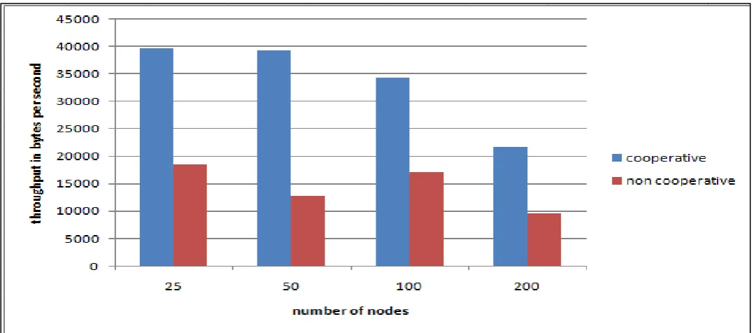
First we simulate a three node network similar to the network in figure 1. A TCP connection was established between the source and destination. And the relay node is always listening to the source transmission and forwarding transmission. That is the destination will have two copies of the same packet if transmission of the source was successful so it will discard the second packet because of the sequence number. While when source fails in the transmission of the packet, the destination will have the relay transmission packet only. The simulation result of the three nodes with cooperation shows very high improvement in the throughput comparing to the results of the node that transmit without cooperation. This is illustrated in figure 4.
Figure 4. Comparing throughput of cooperative communication verse non-cooperative communication
Figure 5. Cooperative and non-cooperative communication average throughput
5.
CONCLUSION AND FUTURE
WORKS
The need of better performance wireless network let cooperative communication an attracting idea for researchers.
[image:5.595.35.576.442.680.2]cooperation. Also the TCP congestion protocol may be revised so that it can have higher performance.
6.
REFERENCES
[1] Kamath, H. Srikanth, “Implementation of Co-Operative Communtication Prortocol”, International Journal of Advanced Computer Research, vol. 3, issue 10, p.163 -171
[2] A. Nosratinia, T. E. Hunter, A. Hedayat. “Cooperative Communication in Wireless Networks,” IEEE Communications Magazine, October 2004.
[3] Y. Peter Hong, W. Huang,C. Kuo, “Introduction,” in Cooperative Communications and Networking, 233 Spring Street, New York, NY 10013, USA: Springer Science+Business Media, 2010, pp. 1-13.
[4] Matthew C. Valenti and Daryl Reynolds, " Distributed space-time block codes," Cooperative Cellular Wireless Networks, Ed. Ekram Hossain, Dong In Kim, Vijay K.Bhargava, Cambridge: Cambridge University Press 2011, 2011, pp. pp. 153-174.
[5] Y. Peter Hong, Wan Huang, C. Jay Kuo, “Two-User Cooperative Transsmission Schemes” in Cooperative Communications and Networking, 233 Spring Street, New York, NY 10013, USA: Springer Science+Business Media, 2010, pp. 67-123 .
[6] P. LIU, Z. TAO, Z. LIN, E. ERKIP, and S. PANWAR, “COOPERATIVE WIRELESS COMMUNICATION: A CROSS-LAYER APPROACH,” IEEE Wireless Communications, August, 2006, p.84-92
[7] T. Korakis, S. Narayanan, A. Bagri, S. Panwar. “Implementing a Cooperative MAC Protocol for Wireless LANs,” in IEEE ICC, 2006, pp. 4805- 4810. [8] K. T. Phan, D. H. N. Nguyen, and T. Le-Ngoc, “Joint
power allocation and relay selection in cooperative networks,” in Proc. of IEEE Global Telecommunications Conference (Globecom), pp. 1–5, Nov. 2009. IEEE, 2009.
[9] K. Fall, K. Varadhan (2011, November 4) , The ns
Manual
![Figure 1. A pair-wise cooperative communication system [3]](https://thumb-us.123doks.com/thumbv2/123dok_us/8033471.769537/1.595.316.553.530.665/figure-pair-wise-cooperative-communication.webp)
![Figure 3. Coded cooperation [1]](https://thumb-us.123doks.com/thumbv2/123dok_us/8033471.769537/3.595.318.562.73.232/figure-coded-cooperation.webp)