Face Recognition under Severe Shadow Effects Using
Gradient Field Transformation
Parisa Beham M
*, Bala Bhattachariar J.U
**, Kasimanikandan K
**, Arun Kumar K
**, Karthigai Selvan M
***
Assistant Professor, Department of ECE , Vickram College of Engineering, Madurai, Tamil Nadu
**
UG student, Department of ECE , Vickram College of Engineering, Madurai, Tamil Nadu
Abstract- In order to detect and eliminate illumination effect, a tensor-based face recognition method is proposed in this paper. In this work, the effect of illuminations is effectively reduced by edge suppression method and gradient field transformation. The use of gradient is taken into account in calculating the direction of the shadows.. In the recognition phase, Principal component analysis is used for feature extraction. The K-nearest-neighbour rule is applied for classification. Experiments are carried out upon the real time as well as standard databases, and the results reveal that the proposed method achieves satisfactory recognition rates under varying illumination conditions.
I. INTRODUCTION
he term digital image processing refers to processing of a two dimensional picture by a digital computer. In a broader context, it implies digital processing of any two dimensional data. A digital image is an array of real or complex numbers represented by a finite number of bits. An image given in the form of a transparency, slide, photograph or an x-ray is first digitized and stored as a matrix of binary digits in computer memory.
Amit Agrawal [1] showed a way in removing the artifacts in an image. In this the colour intensity of the image and some intensity details may be lost. The edges of the image are
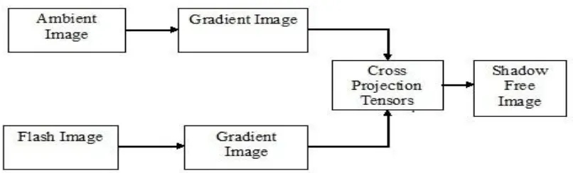
[image:1.612.116.519.531.653.2]suppressed using cross projection tensors [3] to reduce the intensity of the darker regions in the image. In [2] the advantage of the assumption on the chromaticity consistency is taken into account. The ambient light chromaticity is approximately the same as the chromaticity of the diffused light. Magnitude of the difference between chromaticity values of shadow and non-shadow region for difference hue values or different for RGB and HSV colour space show both spaces are used in conjunction by setting threshold on these differences. In [4] the facial regions are taken into account. Each facial region is taken and classified. In this paper, we propose a new method for manipulating image gradient fields based on affine transformation using projection tensors. Our approach provides a principled way of removing scene texture edges from images as compared to thresholding. We make no assumptions on ambient lighting, smoothness of the reflectance or the illumination map and do not use explicit shadow masks. To remove shadow from the ambient image, we need a reflected image, also called as flash image. The gradient of the two images are derived in both x and y directions. The cross projection tensors are derived from the flash image. These tensor values are applied on the ambient image. This will result in shadow free image.
Figure 1: Block diagram for removing shadows from the ambient image using flash image
ISSN 2250-3153
II. PROPOSEDMETHODOLOGY
All images are a combination of primary colors like red, blue, green. These two RGB images are converted into YUV images. This will reduce the number of colour components for processing. These images are converted into gradient images in x-axis component and y-axis component to predict the direction of the shadow in the image. Then cross projection tensors are applied on flash images. This will analyze the scalar and vector components of the two images i.e. flash image and the ambient image. The output is given to the affine transform which is used to rotating, scaling etc. The result of all the above process will result in shadow free image. The shadow free image is let to compare with database image. For this the principle component analysis is used. The principle features are extracted. Eigen vectors and Eigen values are calculated. Now the KNN classifier compares the two images and produces the result. Figure 1 shows the basic block diagram for removing shadow free image.
A. Computing the gradients
We will begin by showing how to compute the gradient at an image location. Then we’ll show that the thing that we compute actually does encode the gradient direction and magnitude. We form the gradient vector by combining the partial derivative of the image in the xdirection and the y direction. ∆I= (∂I/∂x, ∂I/∂y) …(1)
For a continuous function, I(x, y) we could write this as:
(∂I(x,y)/∂x) = lim∆x→0(I(x+∆x,y)-I(x,y))/∆x …(2)
In the discrete case, we can only take differences at one pixel intervals. So we can take the difference between I(x,y) and the pixel before it, or the pixel after it. Using correlation we can treat the pixels before and after I(x,y) symmetrically, and compute:
(∂I(x,y) /∂x) = ( I(x+1,y) - I(x-1,y)) /2 ...(3)
B. Affine transformation on gradient
Let I(x,y) be an intensity image and
denote the gradient vector of I at each pixel. The smoothed structure tensor Gσ is defined as
where ∗ denotes convolution and Kσ is a normalized 2D Gaussian kernel of variance σ. The matrix Gσ can be de-composed as
where v1, v2 denote the eigen-vectors corresponding to the eigen-values λ1, λ2 respectively and λ2 ≤ λ1. The eigen-values and eigen-vectors of Gσ give information about the local intensity structures in the image [2]. For homogeneous regions, λ1 = λ2= 0. If λ2= 0 and λ1 > 0, it signifies the presence of an intensity edge. The eigen-vector v1 (cor-responding to the higher eigen-value λ1) corresponds to thedirection of the edge.
C. Tensors
Tensors are geometric objects that describe linear relations between vectors, scalars, and other tensors. Elementary examples of such relations include the dot product, cross product, and linear map vectors and scalars themselves are also tensors. A tensor can be represented as a multi-dimensional array of numerical values.
D. Self projection tensors
ISSN 2250-3153
an affine transformation of the gradient field. The Eigen Vector v1 of the structure tensor matrix G correspond to the direction of the edge. Suppose we define the self-projection tensor Dself as u1=v1 u2=v2
µ1=0 µ2=1. It is easy to see that an affine
transformation of the image gradient using Dself will remove the local edge.
E. Cross projection tensors
We now show how to remove the scene texture edges from an image by transforming its gradient field using cross projection tensors obtained from a second image of the same scene. The final image is obtained by a 2D integration. If A is also homogeneous (λA1 = 0), set μ1 =μ2 = 0. These results
in If A is also homogeneous (λA1 = 0), set μ1 =μ2 = 0.
These results in
If A is not homogeneous (λA1 > 0), set μ1 = μ2 =
1. This results in
and edges which are in A but not in B can be retained. Else, if there is an edge in B (λB1 > 0),
remove that edge by setting μ1 = 0, μ2 =1.
F..Feature extraction
Feature extraction process can be defined as the procedure of extracting relevant information from a
face image. This information must be valuable to the later step of identifying the subject with an acceptable error rate. The feature extraction process must be efficient in terms of computing time and memory usage. The output should also be optimized for the classification.
G. Principle component analysis
PCA is mathematically defined as an orthogonal linear transformation that transforms the data to a new coordinate system such that the greatest variance by any projection of the data comes to lie on the first coordinate, the second greatest variance on the second coordinate, and so on. The main idea of using PCA for face recognition is to express the large 1-D vector of pixels constructed from 2-D facial image into the compact principal components of the feature space. Principal component analysis (PCA) has been called one of the most valuable results from applied linear algebra. PCA is used abundantly in all forms of analysis from neuroscience to computer graphics because it is a simple, non-parametric method of extracting relevant information from confusing data sets. With minimal additional effort
Figure 2: Block diagram of classification of images by KNN classifier
PCA provides a road map for how to reduce a complex data set to a lower dimension to reveal the sometimes hidden, simplified structure that often underlie it.
H. Classification
Classification is a process of grouping up of similar things. In this we are going to classify the test images with the already present database images. For this, we use KNN classifier.
I.K-NN Classifier
= f(x) to every such vectors. A set of T vectors are given together with their corresponding classes: x(i), y(i) for i = 1, 2, . . . , T. This set is referred to as the training set. The problem we want to solve is the following. Supposed we are given a new sample where x = u. We want to find the class that this sample belongs. If we knew the function f , we would simply compute ,v = f(u) to know how to classify this new sample, but of course we do not know anything about f except that it is sufficiently smooth. The idea in K -Nearest Neighbor methods is to identify k samples in the training set whose independent variables x are similar to u, and to use these k samples to classify this new sample into a class, v. If all we are prepared to assume is that f is a smooth function, a reasonable idea is to look for samples in our training data that are near it and then to compute v from the values of y for these samples. The result of KNN classifier is shown
III. RESULTS
We use a flash image F of the scene to remove shadows from the ambient (no-flash) image A. The flash and the ambient images were captured in quick succession using the remote capture utility with the camera mounted on a tripod. We obtain the cross projection tensor DF using F and trans-form the gradient field ∇A using it. Figure 1 shows an ex-ample on a highly textured book. Notice that the recovered shadow free image A‘’ has no color artifacts and the recovered illumination map A‘ is free of strong texture edges on the face of the book. Figure 6 shows a challenging scenario where the hat on the mannequin casts shadows on the given ambient image. Usually, the ambient and flash images have different color tone due to ambient lighting being yellow-reddish and flash illumination being bluish. Our algorithm requires no pre-processing or color calibration and has no color artifacts as compared to the result using gradient projection. One might think that the ratio image AF could give the illumination map of the scene. However, the ratio image (shown in Figure 6) does not represent the illumination map due to the effects of flash shadows (at depth discontinuities) and lighting variations (on top of the hat) due to the flash. The illumination map obtained by our approach better represents the diffuse ambient illumination.
Figure.3 (a) Ambient Image (b) Flash Image
[image:4.612.345.518.49.153.2]
Figure.4. D11 and D12 of cross diffusion tensor
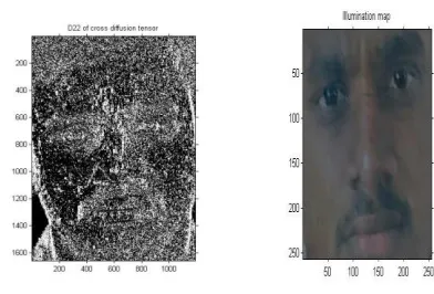
Figure.5. (a)D22 cross diffusion tensor (b)Recovered Illumination map
Figure 6. Shadow free image
[image:4.612.351.531.189.303.2] [image:4.612.348.544.337.470.2] [image:4.612.352.526.524.653.2](Second row) Recovered shadow free image A” and the illumination map A’ . (Last row) Result using gradient projection has visible color artifacts. One cannot obtain the illumination map by taking the ratio A/F (shown on right) which is confounded by shadows due to flash and uneven lighting on the hat. Notice that the white balance in the flash and ambient images is different. Our result does not have any color artifacts. After getting the shadow free image , we can go for classification process. The input query image has been given. The feature extraction using principal component analysis has been processed. The K-NN classifer now compares the query image features with the features which are already stored in the databases. The output is shown in figure.7.
IV. CONCLUSION
We have presented an approach for edge-suppressing operations on an image, based on affine transformation of gradient fields using cross projection tensor derived from another image. The shadow in the ambient image can be removed by this. Though the orientation of the faces, facial reactions are not considered, this project will be useful in many applications. In addition, we have extracted the principle features from two images and compared it with KNN classifier. This can be used in authentication purpose, verification etc. Our approach is simple and easy to handle.
Figure.7. Classifier output
REFERENCES
[1] A. Agrawal, R. Raskar, S. Nayar, and Y. Li. Removing photography artifacts using gradient projection and flashexposure sampling. ACM Trans. Graph., 24(3):828–835, 2005.
[2] Commentary paper on shadow removal in indoor scene by Sofke.M, 2008 [3] Edge Suppression by Gradient Field Transformation using Cross-Projection
Tensors by Amit Agrawal, Ramesh Raskar and Rama Chellappa, 2008. [4] H. Chen, P. Belhumeur, and D. Jacobs. In search of illumination invariants.
In Proc. Conf. Computer Vision and Pattern Recognition, 2000.
[5] A. Agrawal, R. Raskar, S. Nayar, and Y. Li. Removing photography artifacts using gradient projection and flash-exposure sampling. ACM Trans. Graph., 24(3):828–835,2005.
[6] G. Aubert and P. Kornprobst. Mathematical Problems in Im-age Processing: Partial Differential Equations and the Cal-culus of Variations, volume 147 of Applied Mathematical Sciences. Springer-Verlag, 2002.
[7] H. Barrow and J. Tenenbaum. Recovering intrinsic scene characteristics from images. In Computer Vision Systems, pages 3–26, 1978.
[8] H. Chen, P. Belhumeur, and D. Jacobs. In search of illumina-tion invariants. In Proc. Conf. Computer Vision and Pattern Recognition, pages 254–261, 2000.
[9] A. Elgammal, D. Harwood, and L. Davis. Non-parametric model for background subtraction. In Proc. European Conf. Computer Vision, pages 751–767, 2000.
[10] M. Piccardi. Background subtraction techniques: a review. In Proc. IEEE SMC Intl. Conf. Systems, Man and Cybernet-ics, Oct. 2004
AUTHORS
First Author – Ms. Parisa Beham, M.E., (Ph.D), Assistant Professor, Vickram College of Engineering,
Second Author – Bala Bhattachariar J.U. B.E. (Final Year), Electronics and Communication, Vickram College of Engineering, [email protected]
Fourth Author – Arun Kumar K, B.E. (Final Year), Electronics and Communication, Vickram College of Engineering