Citation:
Thomas, F and Fylan, F and David, G and Gorse, C (2017) Developing a taxonomy for discontinuities in internal wall insulation. In: International Sustainable Ecological Engineering Design for Society (SEEDS) Conference 2017, 13 September 2017 - 14 September 2017, Leeds Beckett University, Leeds.
Link to Leeds Beckett Repository record: http://eprints.leedsbeckett.ac.uk/6250/
Document Version:
Conference or Workshop Item
The aim of the Leeds Beckett Repository is to provide open access to our research, as required by funder policies and permitted by publishers and copyright law.
The Leeds Beckett repository holds a wide range of publications, each of which has been checked for copyright and the relevant embargo period has been applied by the Research Services team.
We operate on a standard take-down policy. If you are the author or publisher of an output and you would like it removed from the repository, please contact us and we will investigate on a case-by-case basis.
506
Developing a Taxonomy for Discontinuities in Internal Wall Insulation
Felix Thomas
1, Fiona Fylan
2, David Glew
3and Christopher Gorse
41,2,3,4 Leeds Sustainability Institute, Leeds Beckett University, School of the Built Environment and
Engineering, Leeds/ LS2 9EN, United Kingdom
Keywords: building efficiency, building performance, internal wall insulation
Abstract
Adopting a fabric first approach and installing thermal insulation in existing buildings is one of the most effective methods of improving energy efficiency. The use of internal wall insulation (IWI) has been shown to offer an effective thermal solution, especially where other methods of insulation are unsuitable. However, fitting internal wall insulation is not without risk as discontinuities (gaps) are often found in the insulation layer for a variety of reasons. This can lead to increased flow of heat from the interior to the exterior causing reduced local surface temperatures, which can lead to condensation or mould growth.
Currently there is little or no consistency in the terminology used to discuss such discontinuities in IWI and as such categorising specific types of discontinuities and their relative magnitude and rate of recurrence in practice is difficult. This paper seeks to address the lack of consistency by proposing a taxonomy that practitioners and researchers can use when describing discontinuities in IWI.
This paper brings together the findings from building performance research, part of which involved field studies forensically observing IWI installations. Alongside the site visits, a literature review of IWI research was undertaken to identify the types of discontinuities observed and the terminology used to describe the occurrence and characteristics. From this a taxonomy has been developed to standardise and characterise discontinuities. It is hoped this will improve the understanding of and appreciation for the importance and scale of discontinuities in the industry, in so doing setting out a route for reducing their occurrence. It is also proposed that this taxonomy could be adapted for use in discussion of other insulation types.
1.
INTRODUCTION
As a result of anthropogenic CO2 emissions and climate change, reducing of CO2 production across the world is a widely embraced goal of governments (IPCC, 2014), the UK, for example, has a target of reducing CO2 emissions to 80% of 1990 CO2 emissions by 2050. With around 30% of the UK’s CO2 emissions being attributed to housing energy use (Select Committee on Environmental Audit, 2005) energy efficiency improvements in UK housing stock represent a significant opportunity for carbon reduction.
507
One solution to thermally upgrade the building fabric of these dwellings is the installation of internal wall insulation (IWI), which consists of a layer of insulation material fixed to the internal faces of the dwellings external walls. Weeks et al. (2013) calculate a typically applied IWI retrofit can significantly improve a solid brick wall with a U-value of 1.985 W/m2·K to a U-value of 0.261 W/m2·K after retrofit.
Although the benefits of thermal upgrades are strongly advocated, IWI is not without its potential drawbacks. Achieving full coverage of the IWI layer is often challenging as all obstacles fitted to the wall surfaces need to be removed, relocated or refitted once the insulation is in place. Such obstacles include radiators, kitchen and bathroom fittings, electrical fittings, cabinets etcetera (Weeks et al. 2013). There are also risks of moisture build up within the structure of solid walls since the addition of insulation material on the internal face of external walls changes their hygrothermal behaviour. When internal insulation is fitted the heat flow into the wall is reduced, thus the potential heat flow from internal heat sources to contribute to drying of the wall structure is reduced, potentially leading to the formation of condensation within the wall structure (Kolaitis
et al. 2013; Kloseiko et al. 2015; Madoras et al. 2012). Thermal bridging of internal insulation can
be a significant problem too, Marincioni et al. (2015) describe how without careful consideration of thermal bridging at junctions, when installing IWI, the overall thermal bridging of the external walls is likely to increase.
It may be more difficult to maintain continuity of the thermal insulation layer using IWI compared to external wall insulation (EWI) or cavity wall insulation. EWI may more readily cover the exposed surface, wrapping around the building with less obstruction. Internal wall surfaces are inherently obstructed with internal walls and floors, boxing in of services, radiators, electrical sockets, fitted cupboards and other existing barriers inside the dwelling which prevent full insulation continuity. IWI may therefore be more vulnerable to discontinuities in the insulation layer, thus increasing the number of potential problems this causes. Discontinuities in IWI can be described as constructional thermal bridges, brought about due to constructional detailing (Janssens et al. 2007).
Hens (1998) carried out laboratory tests within an environmental chamber, on a mocked up masonry T-junction with insulation only fitted to the "external" wall section, finding cold surface temperatures at the "partition" section, posing a condensation risk. Work by Little and Arregi, (2011) also identified discontinuities of IWI to be subject to thermal bridging and at risk of condensation formation, particularly wall junctions, where IWI is installed asymmetrically on one side. The side of the party wall without IWI experiences lower surface temperatures and a greater risk of condensation formation.
The form of discontinuities investigated varies across the published literature, due the range of junctions and construction details around which discontinuities of IWI can occur. The language used to refer to discontinuities also differs across publications. This paper aims to develop a logical taxonomy of discontinuities in IWI that can be used to clarify their discussion and assist future research and installation practice.
2.
METHOD
A review of historical research reports for previous site visits to homes with IWI was undertaken. The initial review commenced with a report produced by the Leeds Sustainability Institute Gorse
508
discontinuities, around the location, cause, type and potential scale of impact, were recorded. Following this, a literature review was undertaken using the following key words/ phrases in academic journal article search engines: “internal insulation” “solid wall” “insulation” “solid wall insulation” “retrofit” “thermal bridge”
Papers were included or excluded from the review according to the following rules; relevance to the subject of discontinuities of IWI, sufficient description to identify the characteristics of IWI discontinuity.
Of the papers discovered during literature search, the number for review was narrowed down to nine in total. These were papers found to be relevant to the subject of discontinuities of IWI and that described discontinuities in sufficient detail to be identified and categorised.
Of the dwellings investigated by Gorse et al (unpublished manuscript) 19 underwent retrofit with IWI. Primary data available included survey observations, plan drawings, photographs and infrared thermography, though not all of these were produced for each dwelling. Sufficient survey observations and visual data to positively identify discontinuities of IWI were present for 5 dwellings. Of the 6 dwellings identified, 4 were found to feature discontinuities of IWI.
3.
RESULTS
Three significant mechanisms of heat loss at discontinuities of IWI have been identified through review of literature and field work. Obstructive, Solid; Where the internal insulation layer is obstructed by a solid building element of low thermal resistance which bridges the insulation layer. Obstructive, Void; where the insulation layer is obstructed by a building element containing an air void, allowing air movement within the air void which bypasses the insulation layer. Exposed Sections of external wall that are not fitted with insulation, leaving an area exposed to the internal environment. Information on the geometry as a secondary identifier has also been provided since this was observed to influences the impact of the discontinuity and may therefore be a useful in their characterisation.
3.1.Obstructive, Solid
Hens (1998) investigated the hygrothermal behaviour of solid masonry walls fitted with IWI, using calculation based modelling and laboratory tests in an environmental chamber. Hens investigates a T-junction between a masonry envelope and an inside partition wall with insulation fixed only to the external envelope section. The low thermal resistance of the internal partition wall allows heat to be conducted past the insulation layer, forming a thermal bridge.
Weeks et al (2013) modelled IWI discontinuities that could be found in a typical solid walled building retrofitted with IWI using thermal simulation software to calculate thermal bridging and surface temperatures at junctions. Whereas Hens (1998) investigated an internal partition wall to external wall junction; with IWI fitted symmetrically on either side of the partition wall, Weeks et
al (2013) model a party wall to external wall junction, where IWI is fitted asymmetrically to only
one side of the party wall. Thus we have the same heat loss mechanism acting but two different outcomes owing to differing geometry of the structure at the junctions. In the asymmetrical case, thermal bridging increases and surface temperature decreases on the side without IWI, as can be seen in Figure 1. Thus, a taxonomy needs to consider the primary (heat loss mechanism) and secondary (geometry) nature of the discontinuity. Geometry is considered in Section 3.4.
509
wall from the insulated side reduces even further, whilst beneficial on the insulated side there is greater thermal bridging and reduction in surface temperature on the uninsulated side. Whilst having a greater impact this still shares the characteristics of “obstructive, solid linear- asymmetrical” discontinuity.
Obstructive, Solid discontinuities of IWI were observed in each of the four dwellings investigated by Gorse et al (2017) that were found to contain discontinuities of IWI. In each of these dwellings Obstructive, Solid discontinuities were found at internal wall junctions, consisting of a mix of symmetrical junctions without insulation returns and asymmetrical junctions with returns fitted only on one side. Two dwellings were observed to have no returns fitted at party wall junctions, whilst a discontinuity in this location is unavoidable in a retrofit of a single terraced unit, a return would mitigate thermal bridging on the side undergoing retrofit. In one dwelling Obstructive, Solid discontinuities were observed at junctions between uninsulated party walls and an insulated roof structure.
Cuce and Cuce (2016) measured thermal bridging through a solid masonry partition wall joined to an external masonry cavity wall filled with insulation, an additional 20mm of aerogel insulation was fitted to the external wall on one side of the partition and measurements taken on the insulated side of the wall. Thermal bridging through the partition wall was found to increase significantly after IWI was fitted and although the insulation solution differs, this again represents an “obstructive, solid linear- asymmetrical” discontinuity
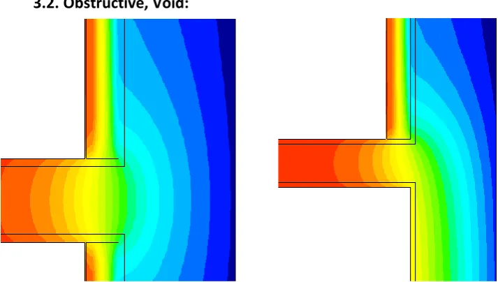
3.2.Obstructive, Void:
[image:5.595.44.401.380.582.2]Obstructive, void discontinuities occur at breaks in the IWI layer due to an obstructive building element that encloses an air void. Air movement within the void allows the IWI layer to be bypassed via convection or advection i.e. air movement into and out of the void is able to take place. Air is able to permeate into and out of the air void, through the often unfinished internal face of the external wall and gaps in wall or floor finishes. Obstructive, void discontinuities share some similarity to exposed discontinuities, as they both involve a section of the face of an external wall that is not covered by insulation, and both can occur simultaneously though their underlying
Figure 1: Heat flow diagrams illustrating a “conductive” discontinuity, in an external wall to brick internal partition wall, in plan view. Left : symmetrical application of IWI. “Obstructive solid linear-Symmetrical” Right : asymmetrical application of IWI.
510
causes and heat loss mechanism differs and as such the potential the impact and remedying solutions are also different, obstructive, void discontinuities requiring mainly proper sealing and air tightness strategies.
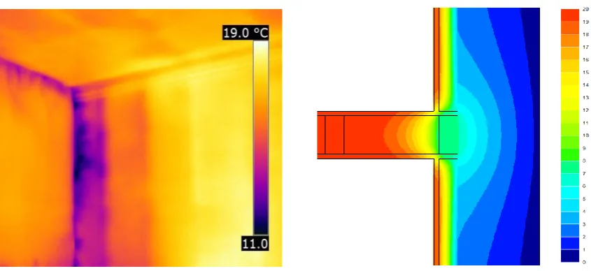
Obstructive, Void discontinuities were present in three of the four dwellings identified, occurring at intermediate floor to external wall junctions in three dwellings and at stud partition walls in two dwellings. Thermography undertaken during depressurisation indicated that air infiltration was occurring at the obstructive, void discontinuities. In one case an attempt to eliminate the discontinuity at the intermediate floor junction was made, filling the gap in the insulation layer with insulation board offcuts. This appears to have been ineffective at preventing air infiltration.
Harrestrup and Svendsen (2016) investigated uninsulated floor voids in a building fitted with IWI and found that the cold temperatures at the uninsulated inner face of the solid external wall and boxed in 200mm gaps in IWI above and below the floor void were at risk of condensation. They state that a correctly fitted vapour barrier is required to prevent exposure to warm and humid internal air, though they also point out it is difficult to achieve a perfect installation, due to the difficulty of installing an air barrier in an existing dwelling. Weeks et al. (2013) look at an uninsulated intermediate floor void in a dwelling fitted with IWI, simulating the heat flow through the junction, find that with symmetrical insulation coverage on either side of the void there is no risk of condensation in occupied spaces, though the temperature of the interior face of the external wall is found to be around 8-10 °C. Weeks et al also model an intermediate floor void with asymmetrically applied IWI (insulation above floor void with none below) in this case wall surface temperatures are higher, reducing condensation risk within the floor void but lower surface temperatures on the uninsulated side pose a condensation risk within the living space.
[image:6.595.59.482.460.654.2]The quality of construction and state of the existing fabric can affect the heat loss through discontinuities with air voids. External air can penetrate through the solid masonry walls, through cracks, damaged pointing and air gaps within the wall itself. Gaps around timber joists where they
511
penetrate the external wall can be a significant source of air leakage. Air exchange between void spaces and the internal environment can also lead to further heat loss, potentially posing a condensation risk as warm, moist air enters the void and reaches the cold face of the external wall (Harrestrup and Svendsen, 2016). Making partition walls and intermediate floors air tight as part of a retrofit can be difficult and prohibitively expensive (Banfill et al, 2012).
3.3 Exposed:
An exposed discontinuity occurs where there is a part of the internal face of the external walls of a dwelling that is exposed to the internal environmental conditions, due to a gap in the coverage of the IWI layer. Marincioni et al. (2016) investigates what impact thermal bridging at discontinuities in IWI at the window and door opening reveals has on the overall heat loss coefficient of typical mid and end terraced solid walled dwellings. They model the heads, jambs
and sills of openings in the external walls, with and without insulation applied to the reveals. Uninsulated reveals are shown to account for a large proportion of the heat lost through all junctions, 40-52% in walls with varying thicknesses of IWI, falling to 19-34% with a 20mm thickness of insulation at the reveals. Weeks et al (2013) also investigate opening reveals, modelling heads, jambs and sills with 100mm of IWI and uninsulated reveals, and the same junctions with 20 mm of insulation. Their results show a reduction in thermal bridging at the junctions of 75 to 82% when insulation is applied to reveals, application of insulation at the reveals also reduces the risk of condensation formation where the window frame joins the solid wall, as the cold surface temperatures caused by thermal bridging are mitigated by the reveal insulation. This means
exposed discontinuity can occur on any insulated wall within a single dwelling where there is a
[image:7.595.87.454.256.514.2]break for whatever reason in the insulation layer. Gorse et al (2017) observed exposed discontinuities in a number of dwellings, including window and door openings with lintels, jambs and sills that were left uninsulated. Areas of external wall without insualtion applied were also
512
observed behind bathroom and kitchen fittings, in these cases IWI was fitted around the existing features, rathern than remove and reinstall them after insulation work was completed.
Odgaard et al (2015) investigates a more unusual scenario, modelling a segment of wall in a typical Danish solid walled dwelling. The wall varies in thickness due to structural “brick columns” that are also part of the external envelope. Simulations are carried out with IWI placed between the brick columns; leaving the columns exposed and with IWI fully covering the wall, including the brick columns. Odgaard found heat flow through the modelled wall was reduced by 19-26% when full IWI coverage was applied, depending on the thickness of insulation used in the model. Harrestrup and Svendsen (2016) investigate the risks of moisture and mould on structural timber members embedded within solid walls with IWI, in particular exploring the effect of leaving 200mm of wall exposed without insulation above and below an uninsulated floor void. Whilst this approach leads to warmer temperatures in the walls around timber members and reduces the moisture risk to the timbers, the surface temperature at the 200mm of exposed wall poses a risk of condensation formation. This discontinuity could be categorised as “Exposed
linear-asymmetrical”
3.4 Geometry
Geometry is an important factor in the characterisation of a discontinuity of the internal insulation layer in a building. The geometry of a discontinuity can play a part in the magnitude of heat loss and moisture risks that occurs at a discontinuity. Geometry of discontinuity can be grouped into three archetypes: Linear; point/ Area; and Opening.
Linear describes a discontinuity that occurs in a straight line, often along the length of a junction between two planar elements of the building fabric, for example a junction between the external wall and a partition wall or an external wall and a floor. Insulation application at linear discontinuities can also be categorised as Symmetrical or Asymmetrical, in symmetrical cases insulation is applied identically on either side of the linear discontinuity, whereas in an asymmetrical case the application of insulation differs on either side or is simply not applied on one side. The effect of asymmetrical insulation along a linear discontinuity were investigated by Weeks et al. (2013), Little and Arregi (2011) and Cuce and Cuce (2016)
Point/ Area discontinuities, as the name suggests, occur over an area or point of the building fabric. The discontinuity may be because of an obstruction or feature preventing full insulation coverage of the external wall, such as architectural features that create an uneven surface making the application of insulation difficult, such as the walls investigated by Odgaard et al. (2015). An area discontinuity may intersect a linear junction or abutting feature, but the condition of the wall is better defined as an area discontinuity. The abutting feature renders the wall less treatable with insulation but does not describe its final condition, which is a large area of uninsulated surface.
Opening discontinuities are those that occur around openings on the external walls of a buildings, this includes sills, heads and jambs. Opening discontinuities are similar in nature to linear discontinuities, as they occur over the length of a linear junction, however the heat loss path is shorter than a discontinuity through the full thickness of a wall (Sierra et al. 2015) as the heat only needs to bypass the window or door frame placed in the opening of the wall.
3.5 Taxonomy
513
The table below explains this in detail. It is proposed that this structure and can be used by any researcher or practitioner to characterise and explain any IWI discontinuity they observe.
Mechanism
Obstructive, solid A solid interruption of the IWI layer with a thermal resistance lower than that of the IWI, extending away from the external wall beyond the IWI layer such as a solid masonry partition wall or a solid floor. Obstructive, void An interruption of the IWI layer that encloses an air void, through
which air can move, bypassing the IWI layer. Examples include a stud partition wall or a timber intermediate floor.
Exposed An area of external wall without, or with much reduced thickness of IWI applied, that is exposed to internal conditions Examples include window reveals without insulation and gaps left to avoid interfering with services.
Geometry
Linear The discontinuity occurs in a straight line or over the length of a single junction such as the junction between a partition wall and an external wall.
Symmetrical/ Asymmetrical Sub classification of linear, insulation is placed symmetrically on both sides of a discontinuity or placed asymmetrically with insulation on one side only.
Point/ area The discontinuity occurs at an isolated location and does not run along a junction in the building fabric. May be located at an isolated obstruction or penetration through building fabric.
Opening The discontinuity occurs around an opening in the external walls of the building. Window/door jambs, lintels and sills
4.
DISCUSSION
The taxonomy that has been developed in this paper is intended to be flexible in its application, capable of being used to characterise discontinuities of IWI independent of the specific material properties of the building fabric and the exact construction methods employed. It is anticipated that using this taxonomy will simplify the comparison and discussion of discontinuities of IWI installations, where the nature of discontinuities present is similar but the building fabric or construction methods may be dissimilar.
Despite the intention to make the taxonomy simple to use and categorise discontinuities, there will be some scenarios where a discontinuity does not neatly fall into one category. In these cases, the nature of the discontinuity should be considered and the most appropriate category chosen. For example, insulation may not have been placed behind a bath that has been boxed in but not sealed. in this example there is a section of uninsulated external wall that is within an air space enclosed by the boxing in of the bath. Whilst the described discontinuity could arguably be categorised as obstructive, void area, exposed area would be a more suitable categorisation, as bypass takes place within a large space that will behave more like an open room, as the air space is large and unsealed. The area geometry is used as although the discontinuity is located next to a linear junction, it is not part of the makeup of the junction.
The intended users for the taxonomy developed in this paper are primarily researchers in the field of building performance, it is also intended for use by practitioners in the fields of surveying,
514
design and construction. The terminology used is intended to be simple and informative, it is expected that becoming familiar with the taxonomy will help practitioners to identify and categorise discontinuities and thus be able to take remedial actions to reduce their impacts, leading to higher quality IWI installations.
Although the vocabulary used in the taxonomy developed in this paper is intended to be simple, it may still prove confusing to an individual that is not familiar with its use. The issue of commensurability of the taxonomy developed in this paper arises. Kuhn (1969) postulates where scientific theories do not share a common vocabulary they cannot be compatible with one and other and are incommensurable. From a more practical perspective the commensurability of the vocabulary of the taxonomy in this paper and that used to discuss discontinuities in other published works can be considered. Most literature simply refers to the discontinuities in question as junctions and provide descriptions of the makeup and nature of thermal bridging that may take place. The taxonomy in this paper is made up of terms that represent concepts that will be familiar to a practitioner in the field of construction and retrofitting of dwellings.
5.
CONCLUSION
This paper has reviewed the literature available on discontinuities in IWI to define their characteristics based on their underlying causes and their impact. A Taxonomy is proposed to categorise in a shortened and simplified way the character of the discontinuity according first to three distinct forms of discontinuity and second to four particular geometrical situations. This organisational structure embedded in the definitions provides universal shorthand that conveys the nature and form of a discontinuity, quickly and simply. This not only relieves some of the reliance on describing the constructional makeup of a discontinuity, which can be time-consuming, but also assists in identifying the potential impact on the building that may be expected. This taxonomy is particularly useful as each category is derived from a particular cause and has a likely impact and, therefore, a distinct solution to remedying each discontinuity may be quickly diagnosed.
References
Banfill, P. Simpson, S. Haines, V. and Mallaband, B. (2012) Energy‐led retrofitting of solid wall dwellings:
technical and user perspectives on airtightness, Structural Survey, Vol. 30 Issue: 3, pp.267-279
BRE (2008). Energy Analysis Focus Report: A Study of Hard to Treat Homes using the English House
Condition Survey – Part 1: Dwelling and Household Characteristics of Hard to Treat Homes. Building
Research Establishment, Watford
Cuce, E. and Cuce, P. M. (2016) The impact of internal aerogel retrofitting on the thermal bridges of
residential buildings: An experimental and statistical research. Energy and Buildings 116, pp 449-454.
Elsevier
Department for Communities & Local Government- UK Gov. (2013) English housing survey-Energy
efficiency of English housing: Annual report on England’s households and housing stock, 2013. London,
Department for Communities and Local Government.
515
Harrestrup, M. and Svendsen, S. (2016) Internal insulation applied in heritage multi-storey buildings with
wooden beams embedded in solid masonry brick façades. Building and Environment 99, pp. 59-72.
Elsevier
IPCC (2014): Climate Change 2014: Synthesis Report. Contribution of Working Groups I, II and III to the
Fifth Assessment Report of the Intergovernmental Panel on Climate Change [Core Writing Team, R.K.
Pachauri and L.A. Meyer (eds.)]. IPCC, Geneva, Switzerland, 151 pp.
Janssens, A., Londersele, E., Vandermarcke, B., Roels, S., Standaert, P. and Wouters P. (2007)
Development of limits for the linear thermal transmittance of thermal bridging buildings. In: Proceedings of tenth thermal performance of the exterior envelopes of while buildings conference: 30 years of
research. 2-7 December 2007, Clearwater Beach, USA. American Society of Heating, Refrigerating and
Air-Conditioning Engineers, Atlanta.
Kolaitis, D. I., Malliotakis, E., Kontogeorgos, D. A., Mandilaras, I., Katsourinis, D.I. and Founti M. A., (2013)
Comparative assessment of internal and external thermal insulation systems for energy efficient retrofitting of residential buildings. Energy and Buildings 64, pp 123-131. Elsevier.
Kloseiko, P., Arumagi, E. and Kalamees, T. (2015) Hygrothermal performance of internally insulated brick
wall in cold climate: A case study in a historical school building. Journal of Building Physics. Vol 38(5) pp
444-464. Sage Publications.
Kuhn, TS. (1970) The Structure of Scientific Revolutions 2nd Ed. University of Chicago Press, Chicago Ill, USA
Little, J. and Arregi, B. (2011) Thermal Bridging: Understanding its Critical Role in Energy Efficiency.
Construct Ireland, April/May, 5 (6).
Marincioni, V., May, N. and Altamirano-Medina, H. (2015) Parametric study on the impact of thermal
bridges on the heat loss of internally insulated buildings. 6th International Building Physics Conference,
IBPC 2015. Energy Procedia 78 (2015) 889 – 894
Marincioni, V., Altamirano-Medina, H., May, N. and Sanders C. (2016) Estimation the impact of reveals on
the transmission heat transfer coefficient of internally insulated solid wall dwellings. Energy and Buildings
128, pp. 405-412. Elsevier
Moradias, P.A., Silva, P.D., Castro-Gomes, J.P., Salazar, M. V. and Pires, L. (2012) Experimental study on
hygrothermal behaviour of retrofit solutions applied to old building walls. Construction and Building
Materials 34, pp 864-873. Elsevier.
Odgaard, T., Bjarløv, S. P., Rode, C. and Venderløkke, M. (2015) Building renovation with interior
insulation on solid masonry walls in Denmark – A study of the building segment and possible solutions. 6th International Building Physics Conference, IBPC 2015. Energy Procedia 78 (2015) pp 830-835. Elsevier Select committee on Environmental Audit, 2005. Environmental Audit – First Report: Housing
Construction. (HC 135 II, 2004-2005). London: The Stationary office. Para. 122
Sierra, F., Bai, J. and Maksoud, T. (2015) Impacts of the simplification of the methodology used to assess
the thermal bridge of the heat of an opening. Energy and Buildings 87 pp 342-347. Elsevier
Weeks, C., Ward, T. and King, C. (2013) Reducing Thermal Bridging at Junctions When Designing and