University of Windsor University of Windsor
Scholarship at UWindsor
Scholarship at UWindsor
Electronic Theses and Dissertations Theses, Dissertations, and Major Papers
10-5-2017
Meso-scale modelling of deformation, damage and failure in dual
Meso-scale modelling of deformation, damage and failure in dual
phase steels
phase steels
Iman Sari Sarraf University of Windsor
Follow this and additional works at: https://scholar.uwindsor.ca/etd
Recommended Citation Recommended Citation
Sari Sarraf, Iman, "Meso-scale modelling of deformation, damage and failure in dual phase steels" (2017). Electronic Theses and Dissertations. 7296.
https://scholar.uwindsor.ca/etd/7296
Meso–Scale Modelling of Deformation, Damage
and Failure in Dual Phase Steels
By
Iman Sari Sarraf
A Dissertation
Submitted to the Faculty of Graduate Studies
through the Department of Mechanical, Automotive & Materials Engineering
in Partial Fulfilment of the Requirements for
the Degree of Doctor of Philosophy
at the University of Windsor
Windsor, Ontario, Canada
2017
c
Meso–Scale Modelling of Deformation, Damage and Failure
in Dual Phase Steels
by
Iman Sari Sarraf
APPROVED BY:
P. Manach, External Examiner
Universit´e de Bretagne-Sud
W. Altenhof
Department of Mechanical, Automotive & Materials Engineering
A. Alpas
Department of Mechanical, Automotive & Materials Engineering
V. Stoilov
Department of Mechanical, Automotive & Materials Engineering
S. F. Golovashchenko, Special Committee Member
K. P. Boyle, Special Committee Member
D. E. Green, Advisor
Department of Mechanical, Automotive & Materials Engineering
Declaration of Co-Authorship and
Previ-ous Publication
I Co-Authorship Declaration
I hereby declare that this dissertation incorporates material that is the result
of joint research undertaken in collaboration with Dr. Sergey Golovashchenko,
Dr. Kevin P. Boyle, Dr. Javad Samei, Dr. Amir Hassannejadasl, Mr. Arash
Jenab, Mr. Dan Mario Vasilescu, Mr. Yang Song, and Mr. Brent McCallum
under the supervision of Prof. Daniel E. Green, University of Windsor. In
addition, Dr. Javad Samei and Mr. Brent McCallum provided the material
characterization of DP600 steel sheets, and Mr. Dan Mario Vasilescu and Mr.
Yang Song collaborated in performing rolling with subsequent uniaxial tension
tests. In all cases, the key ideas, the primary contributions, simulations and data
analysis and interpretations were performed by the author of this dissertation.
The contributions of the co-authors were primarily focused on the provision of
the study and suggesting possible directions. Results related to this research are
reported in Chapters 4 through 7, inclusively.
I am aware of the University of Windsor’s Senate Policy on Authorship and I
certify that I have properly acknowledged the contributions of the other researchers
to my dissertation, and I have obtained written permission from my co-authors
to include the above materials in my dissertation. I certify that, with the above
qualification, this dissertation, and the research to which it refers to, is the product
of my own work.
II Declaration of Previous Publication
This dissertation includes 3 original papers that have been previously
Dissertation Chapter
Publication title/full citation Publication Status
Chapter 4 I. S. Sarraf, A. Jenab, K. P. Boyle, and
D. E. Green. “Damage evolution and void coalescence in finite-element modelling of DP600 using a modified Rousselier model” Materials & Design 117 (2017): 267-279.
Published
Chapter 5 I. S. Sarraf, D. E. Green, and A. Jenab.
“Damage evolution and void coalescence in finite-element modelling of DP600 during uniaxial tensile testing using a modified Rousselier model”
Submitted, Jul. 20,
2017, Engineering
Fracture Mechanics
Chapter 6 I. S. Sarraf, D. E. Green, D. M.
Vasilescu, and Y. Song. “Numerical analy-sis of damage evolution and formability of DP600 sheet with an extended Rousselier damage model”
Submitted, May. 8,
2017, International
Journal of Solids and Structures
I certify that I have obtained a written permission from the copyright owners to
include the above published materials in my dissertation. I certify that the above
material describes work completed during my registration as graduate student at the
University of Windsor.
I declare that, to the best of my knowledge, my dissertation does not infringe upon
anyone’s copyright nor violate any proprietary rights and that any ideas, techniques,
quotations, or any other material from the work of other people included in my
dissertation, published or otherwise, are fully acknowledged in accordance with the
standard referencing practices. Furthermore, to the extent that I have included
copyrighted material that surpasses the bounds of fair dealing within the meaning of
the Canada Copyright Act, I certify that I have obtained a written permission from
the copyright owners to include such materials in my dissertation.
dissertation has not been submitted for a higher degree to any other University or
Abstract
Advanced high strength steels (AHSS), such as dual phase (DP) and transformation
induced plasticity (TRIP) steels, offer high ductility, formability, and strength, as
well as high strength-to-weight ratio and improved crash resistance. Dual phase steels
belong to a family of high strength grades which consist of martensite, responsible
for strengthening, distributed in a ductile ferrite matrix which accommodates the
deformation throughout the forming process. It has been shown that the predominant
damage mechanism and failure in DP steels depends on the ferrite and martensite
grain sizes and their morphology, and can range from a mixture of brittle and ductile
rupture to completely ductile rupture in a quasi-static uniaxial tension test. In this
study, a hybrid finite element cellular automata model, initially proposed by Anton
Shterenlikht (2003), was developed to evaluate the forming behaviour and predict
the onset of instability and damage evolution in a dual phase steel. In this model,
the finite element constitutive model is used to represent macro-level strain gradients
and a damage variable, and two different cell arrays are designed to represent the
ductile and brittle fracture modes in meso-scale. In the FE part of the model, a
modified Rousselier ductile damage model is developed to account for nucleation,
growth and coalescence of voids. Also, several rate-dependent hardening models were
developed and evaluated to describe the work hardening flow curve of DP600. Based
on statistical analysis and simulation results, a modified Johnson-Cook (JC) model
and a multiplicative combination of the Voce-modified JC functions were found to be
the most accurate hardening models.
The developed models were then implemented in a user-defined material subroutine
(VUMAT) for ABAQUS/Explicit finite element simulation software to simulate
electrohydraulic free-forming (EHFF). The modified Rousselier model could
success-fully predict the dynamic behaviour, the onset of instability and damage progress
in DP600 tensile test specimens. Also, the forming limit curve (FLC) as well as the
final damage geometry in DP600 Marciniak specimens was successfully predicted and
compared with experiments. A hybrid FE+CA model was utilized to predict the
major fracture mode of DP600 and DP780 sheet specimens under different deformation
conditions. This hybrid model is able to predict quasi-cleavage fracture in ultra-fine
and coarse-grained DP600 and DP780 at low and high strain rates. The numerical
results showed the capabilities of the proposed model to predict that higher
marten-site volume fraction, greater ferrite grain sizes and higher strain rates promote the
brittle fracture mechanism whereas finer grain sizes and higher temperature alter the
Dedication
To my beloved wife, Niloufar
and
Acknowledgements
First and foremost, I would like to express my deepest gratitude to my experienced
advisor, Dr. Daniel E. Green for his relentless guidance, care, patience, and for
providing me with excellent help and support for conducting research. His positive
outlook and encouragements in my research inspired me and gave me confidence and
motivation to pursue my research interest. Thank you for believing in me and giving
me a unique opportunity to work on such an important and interesting topic. He is,
by far, one of the best supervisors one can imagine.
I would also like to express my appreciation to my industrial supervisor, Dr. Kevin P.
Boyle at CanmetMATERIALS whose help and guidance was second-to-none during my
PhD program. He helped me develop my coding skills and my knowledge in materials
science and engineering. I would also like to thank the rest of my committee: Dr.
Alpas, Dr. Altenhof and Dr. Stoilov for their help, guidance and support. I thank
Lucian Blaga at CanmetMATERIALS for teaching me the DIC technique and Connie
Barry at MARC for helping me with X-Ray tomography tests.
I would also like to acknowledge the role of my closest friend, Arash, who has been a
great friend/brother both in my personal and academic life for the past eleven years.
He helped me and pushed me a lot during different stages of my research. I would like
to thank all of my friends in Windsor and Hamilton for their kind and unbelievable
support and assistance.
I owe a great debt of gratitude to my parents who raised me up “to more than I
can be”. Their constant, continuous and infinite love, sacrifices, encouragements and
supports helped me to move forward in my life. I would like to thank my sister,
Naghme, who is the main inspiration of my life, whose limitless kindness and support
helped me a lot through different stages of my life. Finally, I would like to say billions
of thanks to my beloved wife, Niloufar, for her infinite and unconditional support,
love, and encouragement. Without her persistent help, this work would not have been
Contents
Declaration of Co-Authorship and Previous Publication iii
Abstract vi
Dedication viii
Acknowledgements ix
List of Figures xiv
List of Tables xxi
Nomenclature xxii
1 Introduction 1
1.1 Dual phase steels . . . 1
1.2 Hybrid finite element cellular automata method . . . 3
1.3 Objectives of the research . . . 5
1.4 Structure of the dissertation . . . 7
1.5 Bibliography . . . 8
2 Literature review 11 2.1 Advanced high strength steel . . . 11
2.1.1 Dual phase steel . . . 12
2.2 Phenomenological damage models . . . 20
2.2.1 Johnson-Cook model . . . 20
2.2.2 MMC model . . . 22
2.2.3 GISSMO model . . . 24
2.3 Micromechanical damage models . . . 26
2.3.1 McClintock model . . . 27
2.3.2 Rice-Tracey model . . . 28
2.3.3 Gurson-Tvergaard-Needleman model . . . 29
2.3.4 Rousselier model . . . 31
2.4 Brittle damage models . . . 34
2.4.1 Crack nucleation . . . 35
2.4.2 Folch . . . 37
2.5 Hardening constitutive functions . . . 38
2.5.1 Strain dependent models . . . 38
2.5.2 Rate and temperature dependent models . . . 39
2.6 Void nucleation functions . . . 41
2.7 Void coalescence criteria . . . 43
2.8 Post-coalescence regime . . . 47
2.9 Summary . . . 47
2.10 Bibliography . . . 48
3 Material model framework 66 3.1 An introduction to cellular automata . . . 66
3.2 Hybrid model description . . . 69
3.2.1 Ductile cell array . . . 72
3.2.2 Brittle cell array . . . 73
3.2.3 Transfer rule . . . 75
3.2.4 The model cycle . . . 78
3.3 Bibliography . . . 81
4 Effect of rate-dependent constitutive equations on the tensile flow behaviour of DP600 using Rousselier damage model 85 4.1 Introduction . . . 86
4.2 Constitutive modelling . . . 88
4.2.1 Rousselier damage model . . . 88
4.2.2 Hardening constitutive models . . . 89
4.3 Material and Methods . . . 92
4.3.1 Material . . . 92
4.3.2 Experimental procedure . . . 92
4.3.3 Fitting procedure . . . 94
4.3.4 FEM . . . 96
4.4 Results and Discussion . . . 98
4.4.1 Fitting results and statistical analysis . . . 98
4.4.2 Finite element simulation . . . 105
4.5 Conclusions . . . 116
4.6 Bibliography . . . 118
5 Damage evolution and void coalescence in finite-element modelling of DP600 using a modified Rousselier model 124 5.1 Introduction . . . 125
5.2.1 Rousselier . . . 128
5.2.2 Hardening models . . . 129
5.2.3 Void nucleation . . . 131
5.2.4 Void coalescence criteria . . . 132
5.2.5 post coalescence regime . . . 134
5.2.6 Implementation procedure . . . 134
5.3 Methodology . . . 135
5.3.1 Material . . . 135
5.3.2 Experimental procedures . . . 137
5.3.3 Finite element model . . . 138
5.3.4 Material properties . . . 139
5.4 Results and discussion . . . 141
5.4.1 Hardening functions . . . 141
5.4.2 Finite element simulation . . . 143
5.4.3 X-ray tomography . . . 152
5.4.4 Performance of the modified damage model . . . 155
5.5 Conclusions . . . 162
5.6 Bibliography . . . 163
6 Numerical analysis of damage evolution and formability of DP600 sheet with an extended Rousselier damage model 170 6.1 Introduction . . . 171
6.2 Constitutive modelling of ductile fracture . . . 174
6.2.1 Micromechanical damage model . . . 174
6.2.2 Void nucleation function . . . 176
6.2.3 Void coalescence criterion and post coalescence regime . . . . 177
6.3 Material and methods . . . 179
6.3.1 Material properties . . . 179
6.3.2 Uniaxial tensile tests . . . 181
6.3.3 Uniaxial tensile tests combined with incremental rolling . . . . 182
6.3.4 Marciniak tests and strain measurement . . . 184
6.3.5 Finite element model . . . 185
6.4 Results and discussion . . . 188
6.4.1 Extended uniaxial tension flow curve . . . 188
6.4.2 Quasi-static formability of DP600 sheet . . . 191
6.4.3 Analysis of damage evolution . . . 192
6.4.4 Void coalescence criterion . . . 197
6.4.5 Strain evolution and necking criterion . . . 199
6.4.6 Necking and failure . . . 202
6.5 Summary and conclusions . . . 208
6.6 Acknowledgements . . . 210
7 Hybrid FE+CA results and discussion 218
7.1 Microstructural properties . . . 218
7.2 Illustration of the performance of the model . . . 223
7.3 Parametric study . . . 229
7.4 Simulation of electrohydraulic forming (EHF) . . . 243
7.5 Bibliography . . . 253
8 Overall summary and conclusions 257 8.1 Overall summary . . . 257
8.2 Conclusions . . . 258
8.3 Originality of the research . . . 262
8.4 Future work recommendations . . . 263
8.5 Bibliography . . . 265
A Rousselier Damage Model Integration Procedure 267 A.1 Bibliography . . . 278
B Non-linear Regression 279 B.1 Bibliography . . . 284
C Material properties in ABAQUS 285 D Recommended material parameters 288 D.1 Bibliography . . . 290
E Complementary FE-model information 291
F References to experimental procedures and results 295
List of Figures
1.1 Application of DP steels in a typical automobile . . . 2
1.2 Implementing different functions and criteria in the finite element scale constitutive model . . . 6
2.1 Global diagram of total elongation of AHSS grades in comparison with traditional low-strength and high-strength steels . . . 12
2.2 Schematic diagram of heat treatment methods to obtain dual phase steels 13 2.3 Thermomechanical procedures to obtain coarse-, fine- and ultra-fine grained dual phase steels . . . 14
2.4 Microstructure of a dual phase steel with coarse grain (CG), fine grained (FG) and ultrafine grain (UFG) sizes . . . 14
2.5 Forming limit diagram (FLD) of DP600 obtained in quasi-static and high strain rate conditions . . . 16
2.6 Potential sites for void formation or damage initiation in dual phase steels (DP600) . . . 18
2.7 Fracture surface of tensile specimens indicating an increase in non-uniform deformation with decreasing grain size . . . 19
2.8 Fracture surfaces and formation of grooves, shear and quasi-cleavage fracture in DP600 . . . 20
2.9 3D and 2D representation of the MMC fracture locus for plane stress conditions . . . 24
2.10 Non-linear accumulation of F for εf=0.68 . . . 26
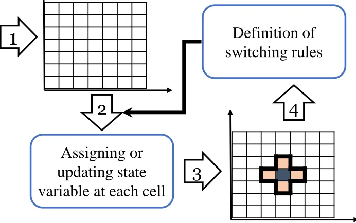
3.1 Different approaches for identifying neighbouring cells . . . 67
3.2 The schematic steps of describing a CA model . . . 67
3.3 The concept of combined finite element and cellular automata models 69 3.4 Numbering and properties of CA neighbouring cells . . . 71
3.7 Sequence of steps performed in the model for each FE integration point
and corresponding CA arrays . . . 81
4.1 Flow curves of DP600 at different strain rates ranging from 0.001 s-1to
1000 s-1 . . . . 94
4.2 Schematic NLR+MCMC procedure used in this study . . . 96
4.3 Geometry of the specimens used for FEA of quasi-static and intermediate
and high strain rate uniaxial tensile tests . . . 98
4.4 Comparison of RMSE of 4 hardening functions in predicting DP600
flow curves in the rolling direction . . . 99
4.5 Cumulative adjusted R-squared value and RMSE calculated for DP600
in the RD testing direction . . . 100
4.6 Experimental and calculated true stress–strain curves and their
corre-sponding slopes for DP600 sheet specimens at 0.001 s-1 . . . 102
4.7 Experimental and calculated true stress–strain curves and their
corre-sponding slopes for DP600 sheet specimens at 100s-1 . . . 103
4.8 Extended DP600 true stress–strain curves predicted by different
hard-ening models at 0.1 s-1 . . . 104
4.9 Comparison of experimental and predicted DP600 flow curves at 0.1
s-1with different D and σI using the KHL and modified–JC hardening
models . . . 106
4.10 Comparison of experimental and predicted engineering stress–strain
curve for DP600 at 0.1 s-1calculated based on different hardening models107
4.11 Variation of scalar damage variable (β) vs. equivalent plastic strain,
cal-culated by Rousselier damage model and different hardening equations
at low and high strain rates . . . 109
4.12 Variation of void volume fraction (f) vs. equivalent plastic strain, based
on different hardening equations at low and high strain rates . . . 110
4.13 History of the evolution of void volume fraction based on different
hardening functions at ˙ε= 0.1 s-1and ˙ε = 100 s-1, and comparison of
void evolution history at different strain rates using modified–JC and
Voce–modified JC hardening laws . . . 112
4.14 Strain distribution along uniaxial tensile test specimens at the onset of necking, using different hardening models comparing to experimental
results at 0.1, 1.0 and 100 s-1. . . 114
4.15 Experimental and predicted damage accumulation and damage geometry
5.1 Flowchart of the implementation of void nucleation and coalescence in
the model . . . 136
5.2 Geometry of the specimens used for finite element analysis of
quasi-static, intermediate and high strain rate uniaxial tensile tests . . . 139
5.3 Comparison of experimental flow stress curves of DP600 (dots) with the
fitted hardening equations (dashed lines) at different strain rates (0.001,
0.1, 1.0, 10, 100 s-1) using modified-JC, KHL, and Voce-modified JC
models . . . 142
5.4 Comparison of experimental tensile strength and values predicted by
constitutive equations at different strain rates for constant true strain
values of 0.03, 0.06, 0.09, 0.12 . . . 143
5.5 Evolution of scalar damage variable calculated by Rousselier damage
model with and without the effect of strain controlled void nucleation at different strain rates using modified-JC and Voce-modified JC hardening
models . . . 145
5.6 Evolution of triaxiality as a function of equivalent plastic strain at
strain-rates 0.1 and 100 s-1using modified-JC and Voce-modified JC . 145
5.7 Variation of void volume fraction as a function of equivalent plastic
strain, based on different constitutive equations at different strain rates with and without the effect of strain controlled void nucleation predicted by the Rousselier damage model and modified-JC and Voce-modified
JC hardening models . . . 146
5.8 Comparison of predicted flow curves by the Rousselier damage model
and different hardening functions, with cluster nucleation (CN) and strain controlled void nucleation (SCVN) functions, with experiment at
strain rates 0.1 and 100 s-1 . . . 148
5.9 The effect of void nucleation function on the variation of plastic
limit-load in the centre of tensile specimens for different hardening functions
using αt= f(n), at (a) 0.1 s-1and (b) 100 s-1calculated by approach #1
and approach #2, respectively. (CN: cluster nucleation, SCVN: strain
controlled void nucleation function . . . 149
5.10 Variation of plastic limit-load in the centre of tensile specimens based
on different approaches in calculating the ligament size ratio (χ) at
(a) 0.1 s-1using modified-JC hardening function and (b) 100 s-1using
Voce-modified-JC hardening model . . . 150
5.11 Variation of plastic limit-load vs. current void volume fraction based
on different hardening functions at strain rate 0.1 s-1with the effect
of cluster void nucleation (CN) and strain controlled void nucleation
5.12 Evolution of plastic limit-load vs. current void volume fraction based
on modified JC at ˙ε = 0.1 s-1using Eq. 5.4 and Eq. 5.7 . . . . 152
5.13 3D representation of the necked area and accumulation of porosities in
the miniature dog-bone specimens at strain rates 1 s-1and 100 s-1. . . 154
5.14 Profile of the porosity percentage on the planes perpendicular to the
load direction at strain rates 1 s-1and 100 s-1 . . . . 155
5.15 Predicted flow curve of DP600 sheet using Rousselier damage model combined with strain controlled void nucleation function and void
coalescence criteria at ˙ε= 0.1 s-1using KHL model and ˙ε= 100 s-1using
Voce-modified JC model . . . 156
5.16 Comparison of experimental results and simulation results predicted by re-determined Rousselier damage model using void nucleation function
and Thomason-Zhang void coalescence criterion . . . 157
5.17 Distribution of the damage accumulation at the onset of necking using different hardening models and void nucleation functions at (a) 0.1 and
(b) 10 and (c) 100 s-1 . . . 159
5.18 Experimental and predicted damage accumulation and damage geometry
at (a) 0.1 and (b) 10 and (c) 100 s-1using different hardening functions,
void nucleation functions and a void coalescence criterion (approach #1:
Eq. 5.4) . . . 161
6.1 Geometry of the uniaxial tension specimen (ASTM E8M) . . . 181
6.2 DP600 specimens used for uniaxial tension combined with incremental
rolling . . . 184
6.3 Schematic of the Marciniak test tooling . . . 185
6.4 Specimen and carrier blank geometries used for the experimental and
FE simulations of Marciniak tests in uniaxial tension, plane strain and
biaxial tension . . . 186
6.5 Finite element model of the Marciniak test (BT). From top to bottom:
punch, blank holder, carrier blank (washer), test piece and bottom die 188
6.6 Comparison of the uniaxial tensile test and extended uniaxial flow
curve of DP600 with the flow curve obtained by bulge tests by different
researchers . . . 189
6.7 Goodness of fit of different hardening laws to the experimental flow
curve of DP600 steel, evaluated by the adjusted R-squared value . . . 190
6.8 Quasi-static forming limit diagram of DP600 steel sheet . . . 191
6.9 Variation of the Rousselier scalar damage variable (β) for three strain
6.10 Variation of the void volume fraction (f) vs. equivalent plastic strain for three strain paths considering 3 void nucleation cases using 4-parameter
Voce and 3-parameter Voce hardening functions . . . 195
6.11 Comparison of the void volume evolution in UT, PS and BT vs. equiv-alent plastic strain for different hardening constitutive equations when
using cluster void nucleation and strain-controlled void nucleation . . 196
6.12 Variation of the plastic limit-load in the centre of the gauge area of Marciniak test specimens for different strain paths (UT, PS and BT) and void nucleation functions using Ludwick, 4-parameter Voce and (c)
-parameter Voce hardening functions . . . 198
6.13 Variation of the major strain during the plane strain Marciniak test using the Rousselier damage model and different void nucleation cases
with the 4-parameter Voce and 3-parameter Voce hardening functions 200
6.14 Determining the bifurcation point from the second derivative of the thickness strain in UT and finding the corresponding major and minor
strains . . . 201
6.15 Comparison of the experimental and numerically predicted DP600 FLC using the Rousselier damage model along with different void nucleation functions, and Ludwick, 4-parameter Voce and 3-parameter
Voce hardening equations . . . 203
6.16 Representation of the Rousselier scalar damage variable at the onset of necking predicted by the proposed procedure in UT, PS and BT defor-mation paths using the Rousselier damage model along with different
hardening models and different void nucleation functions . . . 205
6.17 Experimental and predicted damage accumulation and distribution in UT, (b)PS and (c)BT using different hardening functions and void
nucleation functions as well as a void coalescence criterion . . . 207
7.1 grain size measurements using Clemex and distribution of ferrite grain
size in DP600 sheet specimens . . . 221
7.2 Overall distribution of βf calculated based on f0 . . . 222
7.3 The finite element in the centre of the gauge area and 2D and 3D
representation of initial cell states in the ductile CA array and brittle
CA array . . . 225
7.4 FE input from ABAQUS solver, critical scalar damage variable in ductile
cells, and fracture stress in brittle cells during uniform deformation . 226
7.5 FE input from ABAQUS solver, critical scalar damage variable in ductile
cells, and fracture stress in brittle cells at the onset of localization and
7.6 Number of dead cells required for the entire brittle CA array to be
considered dead with and without coalescence criterion . . . 228
7.7 FE input from ABAQUS solver, critical scalar damage variable in ductile
cells, and fracture stress in brittle cells at the time of failure . . . 228
7.8 FE input from ABAQUS solver, critical scalar damage variable in ductile
cells in pure shear and simple shear tests . . . 229
7.9 Miniature doge-bone model used for parametric study . . . 231
7.10 3D representation of initial understructural arrays of critical Rousselier scalar damage variable for ductile CA array, fracture stress and grain
orientation for brittle CA array . . . 232
7.11 Fraction of brittle fracture in fine-grained (dg=3µm) and coarse grained
(dg=6.5 µm) DP600 specimens . . . 234
7.12 Quasi-cleavage fracture on the fracture surface of DP600 tested under
quasi-static condition . . . 234
7.13 Fraction of brittle fracture in fine-grained (dg=3µm) and coarse grained
(dg=6.5 µm) DP780 specimens . . . 235
7.14 Quasi-cleavage fracture on the fracture surface of DP780 deformed
under quasi-static conditions and at high-strain rate . . . 236
7.15 Total fraction of brittle fracture predicted in fine-grained and
coarse-grained DP600 and DP780 at low and high strain rates . . . 237
7.16 Comparing the effect of grain size on the predicted fraction of brittle
fracture and related experiments in ultra-fine grained (dg=1.5 µm),
fine-grained (dg=3 µm) and coarse-grained (dg=12µm) DP780 specimens238
7.17 Initial brittle cell states in each FE located on the cross-section of the
DP780 miniature dog-bone specimen . . . 240
7.18 Final brittle cell states in each FE located on the cross-section of
ultra-fine grained (dg=1.5 µm) and coarse-grained (dg=12 µm) DP780
specimen . . . 241
7.19 The effect of temperature on the fraction of brittle fracture in
coarse-grained (dg=12 µm) DP780 specimen at ˙ε=1000 s-1 . . . 242
7.20 The effect of ferrite grain size and strain rate on the fraction of brittle
fracture in DP780 tensile specimens . . . 243
7.21 Schematic of the cross-section of the tooling in EHFF and EHDF . . 244
7.22 Finite element model of the EHFF. From top to bottom: blank holder,
sheet specimen and lower die . . . 245
7.24 Nodal acceleration in water used to simulate EHF . . . 247
7.25 Spatial distribution of Pressure-pulse on sheet specimen . . . 248
7.26 Predicted strain path and predicted effective strain rate history in EHFF
for two different levels of input energy . . . 249
7.27 History of plastic strain, Rousselier scalar damage variable and triaxiality
in a damaged element at the apex of DP600 sheet subjected to EHFF 250
7.28 Experimental and predicted damage accumulation in a fractures EHFF
specimen deformed with 9.2 kV, 13.6 kJ input energy . . . 251
7.29 Predicted damage geometry of fracture in DP600 specimens: 10.3 kV
(15.6 kJ),dg=3.5 µm and 9.2 kV (13.6 kJ), dg=12 µm . . . 252
7.30 Total predicted fraction of brittle fracture in fine-grained and coarse-grained DP600 subjected to EHFF with different applied energy values 252
C.1 Material definition and properties used in ABAQUS FE simulation
software . . . 287
E.1 Mesh sensitivity results for quasi-static uniaxial tension test of DP600
specimen . . . 292
E.2 History of internal and kinetic energy throughout the simulation of
uniaxial tension tests at (a) 0.1 s-1and (b) 1 s-1, and Marciniak tests in
(c) PS and (d) BT . . . 293
E.3 Comparison of experimental and calculated average strain in (a) the
List of Tables
4.1 Chemical composition of as-received DP600 steel (wt%) . . . 92
4.2 Coefficients of hardening functions for DP600 determined via NLR+MCMC 98
4.3 Design arrangement of parameters for the calibration process . . . 106
4.4 Rousselier damage model parameters of DP600 . . . 107
5.1 Chemical analysis of as-received DP600 steel (% in weight) . . . 137
5.2 Mechanical properties and damage parameters of the DP600 . . . 140
5.3 Coefficients of hardening functions for DP600 . . . 141
6.1 Chemical composition of the material (wt%) . . . 179
6.2 Mechanical properties of as-received DP600 sheet . . . 179
6.3 Rousselier damage parameters for DP600 . . . 180
6.4 Description of specimens pre-strained by flat rolling . . . 183
6.5 Hardening parameters calculated by NLR for DP600 sheet . . . 190
7.1 Mechanical properties of as-received DP600 . . . 223
7.2 Coefficients of mJC hardening function for DP600 . . . 223
7.3 Coefficients of KHL hardening function for DP600 and DP780 . . . . 231
C.1 List of material properties required for input in ABAQUS . . . 285
D.1 Mechanical properties of as-received DP600 sheet . . . 288
D.2 Hardening parameters calculated DP600 sheet . . . 288
D.3 Coefficients of hardening functions for DP600 . . . 289
Nomenclature
Chapter 4
β scalar damage variable
βc critical damage value at failure
˙
ε0 reference strain rate
˙
εp equivalent plastic strain rate
λ plastic multiplier in the normality rule
σm hydrostatic stress
σs saturation stress
σeq von Mises equivalent stress
εp equivalent plastic strain
B conjugate force of damage parameter
C1...n material constants or predictors in the hardening equations
D , σI adjustable Rousselier damage model parameters
Dp0 upper bound strain rate
E Young’s modulus
f current void volume fraction
f0 initial void volume fraction
fc critical void volume fraction at failure
H hardening curve of the material
Chapter 5
αt , βt Thomason coalescence model coefficients
β scalar damage variable
χ void space Ratio
δ multiplicative void growth acceleration factor
˙
˙
ε0 reference strain rate
η function of void distribution
γ cell geometry related coefficient
λ plastic multiplier in the normality rule
σI maximum principal stress
σm hydrostatic stress
σeq equivalent stress
εc critical strain at the onset of coalescence
εf fracture strain
εN mean strain at void nucleation
εp equivalent plastic strain
εI,II,III principal plastic strains
ϑ current void distribution
ϑ0 initial void distribution
B conjugate force of damage parameter
C1...n fitting parameters of hardening functions
D , σ1 adjustable Rousselier damage model parameters
DP
0 arbitrary upper bound strain-rate
f current void volume fraction
f∗ effective void volume fraction
f0 initial void volume fraction
fc critical void volume fraction at the onset of coalescence
ff void volume fraction at failure
fN volume fraction of void nucleating particles
fu∗ final effective void volume fraction at final damage
H0 initial height of the unit cell
R hardening curve of material
r radius of the void
R0 initial radius of the unit cell
SN standard deviation
W void aspect ratio
CN cluster nucleation
SCVN strain controlled void nucleation
Chapter 6
αt , βt Thomason coalescence model coefficients
β scalar damage variable
βf critical Rousselier scalar damage variable at failure
χ void space Ratio
˙
εp equivalent plastic strain rate
λ plastic multiplier in the normality rule
Φd(f) stored damage energy
Φe(εe) stored elastic energy
Φp(εp) stored plastic energy
σI maximum principal stress
σm hydrostatic stress
σeq equivalent stress
εc critical plastic strain at failure
εe elastic strain
εN mean strain at void nucleation
εp equivalent plastic strain
εI,II,III principal plastic strains
D , σk adjustable Rousselier damage model parameters
f current void volume fraction
f∗ effective void volume fraction
f0 initial void volume fraction
fc critical void volume fraction at the onset of coalescence
ff void volume fraction at failure
fN volume fraction of void nucleating particles
fu∗ final effective void volume fraction at final damage
H(εp) hardening curve of material
n strain hardening exponent
Chapter 1
Introduction
1.1
Dual phase steels
The automotive industry is constantly challenged to decrease fuel consumption, improve
safety, reduce weight and enhance the crash response of auto-body structures [1, 2].
Advanced high-strength steels (AHSS) have been developed to fulfil these requirements
and be used for automotive structural components in order to improve
manufactura-bility, durability and crash-worthiness without corresponding weight increases [3].
Among all AHSS categories, dual phase (DP)-type steels and transformation-induced
plasticity (TRIP)-type steels are the most widely-used. The term dual-phase was first
coined by Hayami and Furukawa as a family of high-strength cold-rolled steels [4].
Dual phase steels are low carbon micro-alloyed steels that usually consist of 70-90
Vol% of ductile ferrite matrix and around 5-30 vol% of dispersed hard martensite.
Usually, small amounts of other phases such as bainite, pearlite or retained austenite
can possibly be found in the DP steel microstructure and can affect their physical and
mechanical properties [5, 6]. This composite microstructure can be achieved through
the special heat treatment regime that consists of inter-critical annealing in theα+γ
The mechanical and forming properties of DP steels, in terms of high ductility and
strength, are the direct result of their composite-like microstructure where the ductile
ferrite matrix contributes to good cold formability and the hard martensite operates
as the strengthening element. The correct proportion of each of the two phases leads
DP steels to exhibit great mechanical characteristics such as continuous yielding, high
strain hardening rates at low strain values and large uniform elongation [7–11], which
results in their increasing application for auto-body members. The application of
various grades of DP steels for different components in a car, such as bumper beam,
A-frame reinforcement, roof bow, B-pillar reinforcement, rear side member, front floor
cross member and floor side reinforcement is shown in Fig. 1.1.
Figure 1.1: Application of DP steels in a typical automobile [12, 13]
To evaluate the forming and failure behaviour of DP steels, different tests have been
carried out at various strain rates ranging from quasi static conditions (0.001 s-1) to
high strain rates (5000 s-1 using a split Hopkinson bar [14, 15]) and strain paths using
different deformation processes and test procedures [16, 17]. Based on obtained
phenomenological or micro-mechanical models, have been developed and calibrated to
be implemented in commercial finite element simulation software such as ABAQUS or
LS-Dyna for formability analysis and for crash simulations.
Due to the microstructure of DP steels and the interaction of ferrite and martensite
grains during a deformation process, four different mechanisms have been identified
for fracture initiation: (a) martensite cracking, (b) decohesion at ferrite-martensite
interfaces, (c) decohesion at ferrite-ferrite interfaces, and (d) decohesion at the interface
between two adjacent martensite grains [6, 18–20]. The main mechanisms of fracture
can alter from a fully ductile fracture mode with dimples and voids to a completely
brittle fracture mode with well-defined facets and cleavage steps on these facets [21].
Nevertheless, conventional numerical approaches and FE simulation software are not
able to distinguish these mechanisms that are directly related to the microstructural
properties of DP steels. Accordingly, new approaches or models should be employed
to fill this gap and take microstructural properties into account.
1.2
Hybrid finite element cellular automata method
The finite element method (FEM) is one of the most widely-used approaches to predict
the stress, strain and temperature distribution, deformation history and damage
accumulation under a specific applied force or forming process and evaluate the
forming and failure behaviour of materials. The accuracy of a FE simulation of a
sheet metal forming process is directly dependent on the constitutive material model
which describes the elasto-plastic behaviour with a hardening function, i.e. true
stress-strain flow curve, and the contact condition. Therefore, different factors should
be evaluated to choose the most accurate and suitable constitutive material model
for a FE sheet metal forming analysis. Moreover, since post-uniform deformation
commences by the formation of a small diffuse or localized necking, a quantitative
prediction of the limiting strain therefore requires assessment of both necking and
failure. It is shown that there are two major sources that contribute to localization:
and surface defects [22–24] and (2) the constitutive behaviour in terms of hardening,
softening and strain-rate sensitivity [25, 26].
As described by Shterenlikht [27], the main problem in conventional finite element
analysis software is that a FE is both a material and a structural unit simultaneously.
Therefore, they fail to address the micro-scale microstructural features and properties
in evaluating the damage mechanisms in non-homogeneous materials. On the other
hand, large numbers of small finite elements are needed to analyse the damage
behaviour and fracture propagation under a certain stress state which results in high
computational cost. Determining the size of elements, to correctly represent the
stress and strain gradients, in the refined meshed region strongly depends on the
nature of possible fracture mechanism due to the microstructural features present in
a material. This makes determining the size scale of finite elements difficult when
simulating the behaviour of multi-phase materials since the finite element mesh in front
of a crack tip should be highly refined due to the physical nature of brittle damage
mechanism whereas the element size for evaluating the ductile fracture mode is a
function of spacing between microvoids or large inclusions which is considerably larger
than that required for evaluating brittle fracture. The only solution in a conventional
FE simulation is to select a compromise mesh size [27, 28]. The main approach for
solving these problems is to separate the material and microstructural properties from
the mechanical properties and move them to another entity. Accordingly, different
numerical models have been established and developed based upon digital material
representation to take the microscale features of different materials into account in
the simulation of various forming processes [6, 29–31].
Although the combination of cellular automata and FE has been used for solidification
or recrystallization of materials, Beynon et al. [32] and Shterenlikht [27, 28] were
the first to utilize it for evaluating forming and damage behaviour of steels. In this
model, the microstructural properties of the material is moved from the finite elements
to an appropriate number of cells in two independent cell arrays, responsible for
ductile and brittle fracture mechanisms. Therefore, the FE mesh is employed to
represent the macro-level strain and stress tensors and damage variables, and the
analyse the microstructural response of the material. In this hybrid (concurrent) finite
element-cellular automata model, the results of different parallel scales are transferred
to each other during each simulation time step. The main advantage of this model is
its capabilities to simulate forming and damage behaviour in a multi-scale domain so
that complex deformation states and their influences on the fracture initiation and
propagation can be assessed [6].
1.3
Objectives of the research
The main objective of this research is to investigate, develop and modify
micro-structurally based models to predict the onset of strain localization and fracture,
and implement the new material model in a user-defined material subroutine for a
commercial finite element simulation software. The model developed in this study is a
combination of finite element analysis method and cellular automata, and has been
implemented in a user material subroutine (VUMAT) that is used in ABAQUS/Explicit
FE simulation software. As shown in Fig. 1.2, the principal steps in development of
the FE model are to:
• conduct a comprehensive review of various micro-mechanical and
phenomenolog-ical constitutive damage models, hardening functions to describe the dynamic
behaviour of the material, void nucleation functions and void coalescence criteria,
• calculate the coefficients of different strain- or strain rate-dependent hardening
functions using an appropriate regression method and advanced optimization
techniques, as well as utilizing statistical analysis and other methods to evaluate
the goodness of the fit and the ability of each existing model and newly developed
function to predict the hardening behaviour of the material,
• investigate the role of the constitutive damage model parameters on the flow
• implement complementary functions and criteria, such as void nucleation
func-tions and void coalescence criteria, in the model to develop a complete constitutive
damage model,
• evaluate the forming and damage behaviour of DP600 subjected to a wide range
of testing and deformation conditions, such as uniaxial tension at different strain
rates ranging from 0.001 s-1 to 1000 s-1, Marciniak tests, and electro-hydraulic
forming (EHF) of laboratory-scale specimens,
• evaluate the capability and performance of the developed damage model in
predicting the onset of necking and fracture in a range of metal forming processes,
including electrohydraulic forming.
FE model
Hardening functions
Void nucleation
functions
Void coalescenc
e criteria Void growth
acceleration functions Damage
model
𝜎 = 𝑓 𝜀 𝜎 = 𝑓 𝜀 , ሶ𝜀 𝜎 = 𝑓 𝜀 , ሶ𝜀 , 𝑇
Constant Linear Controlled
Global and local strength Weakest link Accelerating
the damage Rousselier ductile damage
model
Void coalescence
criteria
Figure 1.2: Implementing different functions and criteria in the finite element scale constitutive model
The principal goals of this research for developing a hybrid finite element-cellular
automata model are to:
• develop a CA model that can take some of the microstructural features into
• identify the role of microstructural features in the damage behaviour of dual
phase steels and their contribution to ductile and brittle fracture mechanisms
in a wide range of deformation conditions, such as uniaxial tension at different
strain rates and electro-hydraulic forming (EHF),
• evaluate the capabilities of the developed hybrid model to perform parametric
studies based on process parameters (such as strain, strain rate and temperature)
and microstructural properties (such as the grain size, and the amount and
distribution of martensite).
1.4
Structure of the dissertation
A brief description of the contents of each chapter is presented in the following:
• Chapter 2 presents a brief review of physical and mechanical properties of
dual phase steels, as well as a review of different phenomenological and
micro-mechanical damage models, void nucleation functions and void coalescence
criteria
• Chapter 3 describes the concept of cellular automata, and explains the
formu-lation of the hybrid FE+CA model
• Chapter 4 defines the non-linear regression (NLR)+ Markov chain Monte
Carlo (MCMC) method to calculate the coefficients of the hardening functions.
Moreover, the calibration procedure of the Rousselier damage model and the
effect of rate-dependent hardening functions on the tensile flow behaviour of
DP600, predicted by the Rousselier model is discussed.
• Chapter 5 defines the implementation procedure of void nucleation functions
and void coalescence criteria, and void growth acceleration function in the
Rousselier damage model. The performance of the modified constitutive model
in predicting the tensile behaviour of DP600 along different strain rates is
• Chapter 6 presents the performance of the modified Rousselier damage model
in predicting the quasi-static forming limit curve (FLC) of DP600. In addition,
damage evolution and accumulation at different strain paths and final damage
geometries are investigated.
• Chapter 7 presents and discusses the results of the hybrid FE+CA model
in terms of ductile and brittle damage evolution and the dominant fracture
mechanism for different forming conditions.
• Chapter 8 presents a summary and conclusions of this research as well as some
suggestions for future work.
1.5
Bibliography
[1] H. Huh, S. B. Kim, J. H. Song, and J. H. Lim, “Dynamic tensile characteristics
of TRIP-type and DP-type steel sheets for an auto-body,” International Journal
of Mechanical Sciences, vol. 50, no. 5, pp. 918–931, 2008.
[2] C. M. Tamarelli, “The evolving use of advanced high-strength steels for automotive
applications,” American Iron and Steel Institute, Southfield, Michigan, 2011.
[3] H. Kim, M. Kimchi, and T. Altan, “Control of Springback in Bending and Flanging Advanced High Strength Steels ( AHSS ),” pp. 1–18, 2009.
[4] S. Hayami and T. Furukawa, “Family of high-strength, cold-rolled steels,” inProc.
Conf. on Microalloying 75, 1977, 311-321, 1977.
[5] J. Kadkhodapour, S. Schmauder, D. Raabe, S. Ziaei-Rad, U. Weber, and M. Calcagnotto, “Experimental and numerical study on geometrically neces-sary dislocations and non-homogeneous mechanical properties of the ferrite phase
in dual phase steels,” Acta Materialia, vol. 59, no. 11, pp. 4387–4394, 2011.
[6] K. Perzy, M. Sitko, and L. Madej, “Numerical Modelling of Fracture Based on Coupled Cellular Automata Finite Element Approach,” pp. 156–165, 2014.
[7] J. M. Rigsbee, J. K. Abraham, A. T. Davenport, J. E. Franklin, and J. W. Pickens, “Structure-processing and structure-property relationships in
commer-cially processed dual-phase steels,” Structure and Properties of Dual-Phase Steels,
[8] A. M. Sarosiek and W. S. Owen, “The work hardening of dual-phase steels at
small plastic strains,”Materials Science and Engineering, vol. 66, no. 1, pp. 13–34,
1984.
[9] S. S. Hansen and R. R. Pradhan, “Structure-property relationships and
continu-ous yielding behavior in dual-phase steels,” Fundamentals of Dual-Phase Steels,
pp. 113–144, 1981.
[10] K.-T. Park, Y. K. Lee, and D. H. Shin, “Fabrication of ultrafine grained
fer-rite/martensite dual phase steel by severe plastic deformation,”ISIJ International,
vol. 45, no. 5, pp. 750–755, 2005.
[11] V. Colla, M. De Sanctis, A. Dimatteo, G. Lovicu, A. Solina, and R. Valentini,
“Strain hardening behavior of dual-phase steels,” Metallurgical and Materials
Transactions A: Physical Metallurgy and Materials Science, vol. 40, no. 11, pp. 2557–2567, 2009.
[12] A. Pineau, “Materiaux et Mobilite,” tech. rep., Centre des Mat´eriaux, Ecole des
Mines de Paris, Saint-Germain-en-Laye, 2012.
[13] J. Fansi, Prediction of DP steel fracture by FEM simulations using an advanced
Gurson model. PhD thesis, Universit´e de Li`ege, 2013.
[14] A. G. Odeshi and M. N. Bassim, “Evolution of adiabatic shear bands in a
dual-phase steel at very high strain rates,” Materials Science and Engineering:
A, vol. 488, no. 1, pp. 235–240, 2008.
[15] W. Wang, M. Li, C. He, X. Wei, D. Wang, and H. Du, “Experimental study on high strain rate behavior of high strength 600–1000MPa dual phase steels
and 1200MPa fully martensitic steels,” Materials & Design, vol. 47, pp. 510–521,
2013.
[16] J. Samei, Multi-scale Characterization of Hyperplasticity and Failure in Dual
Phase Steels Subject to Electrohydraulic Forming. PhD thesis, University of Windsor, 2013.
[17] A. C. Thompson, High strain rate characterization of advanced high strength
steels. PhD thesis, University of Waterloo, 2006.
[18] G. Avramovic-Cingara, C. Saleh, M. Jain, and D. Wilkinson, “Void nucleation
and growth in dual-phase steel 600 during uniaxial tensile testing,” Metallurgical
and Materials Transactions A, vol. 40, no. 13, pp. 3117–3127, 2009.
[19] J. Samei, D. E. Green, and S. Golovashchenko, “Analysis of failure in dual
phase steel sheets subject to electrohydraulic forming,” Journal of Manufacturing
[20] J. Samei, D. E. Green, J. Cheng, and M. S. de Carvalho Lima, “Influence of strain
path on nucleation and growth of voids in dual phase steel sheets,” Materials &
Design, vol. 92, pp. 1028–1037, 2016.
[21] M. Calcagnotto, D. Ponge, and D. Raabe, “Effect of grain refinement to 1µm on
strength and toughness of dual-phase steels,” Materials Science and Engineering:
A, vol. 527, no. 29-30, pp. 7832–7840, 2010.
[22] M. Dao and M. Li, “A micromechanics study on strain-localization-induced
fracture initiation in bending using crystal plasticity models,” Philosophical
Magazine A, vol. 81, no. 8, pp. 1997–2020, 2001.
[23] P. D. Wu, D. J. Lloyd, M. Jain, K. W. Neale, and Y. Huang, “Effects of spatial grain orientation distribution and initial surface topography on sheet
metal necking,” International Journal of Plasticity, vol. 23, no. 6, pp. 1084–1104,
2007.
[24] X. H. Hu, M. Jain, D. S. Wilkinson, and R. K. Mishra, “Microstructure-based finite element analysis of strain localization behavior in AA5754 aluminum sheet,”
Acta Materialia, vol. 56, no. 13, pp. 3187–3201, 2008.
[25] A. K. Ghosh, “Strain localization in the diffuse neck in sheet metal,”Metallurgical
Transactions, vol. 5, no. 7, pp. 1607–1616, 1974.
[26] A. Needleman, “Material rate dependence and mesh sensitivity in localization
problems,” Computer methods in applied mechanics and engineering, vol. 67,
no. 1, pp. 69–85, 1988.
[27] A. Shterenlikht, 3D CAFE modelling of transitional ductile-brittle fracture in
steels. PhD thesis, University of Sheffield, 2003.
[28] A. Shterenlikht and I. C. Howard, “The CAFE model of fracture—application
to a TMCR steel,” Fatigue & Fracture of Engineering Materials & Structures,
vol. 29, no. 9-10, pp. 770–787, 2006.
[29] A. Asgari, H. Ghadbeigi, C. Pinna, and P. D. Hodgson, “Multiscale modelling
of stress and strain partitioning in high strength dual phase steels,” Computer
methods in materials science, vol. 12, no. 3, pp. 163–174, 2012.
[30] N. Vajragupta, V. Uthaisangsuk, B. Schmaling, S. M¨unstermann, A. Hartmaier,
and W. Bleck, “A micromechanical damage simulation of dual phase steels using
XFEM,” Computational Materials Science, vol. 54, pp. 271–279, 2012.
[31] M. Amirmaleki, J. Samei, D. E. Green, I. van Riemsdijk, and L. Stewart, “3D micromechanical modeling of dual phase steels using the representative volume
element method,” Mechanics of Materials, vol. 101, pp. 27–39, 2016.
[32] J. H. Beynon, S. Das, I. C. Howard, E. J. Palmier, and A. Shterenlikht, “The combination of cellular automata and finite elements for the study of fracture;
Chapter 2
Literature review
2.1
Advanced high strength steel
There is an increasing demand in the automotive industry to reduce both vehicle
weight and gas emissions, and increase fuel efficiency. Therefore, significant effort and
energy have been invested to develop suitable materials which can exhibit excellent
performance in terms of combined high ductility and strength [1, 2]. Automotive
steels can be categorized based upon their metallurgical designation to low strength
steels, e.g. interstitial free (IF) and mild steels, conventional HSS (carbon manganese,
bake hardenable and high-strength, low-alloy steels), ultra-high strength steels (UHSS)
and new advanced high strength steels (AHSS), such as dual phase steels (DP),
transformation induced plasticity (TRIP) steels. The latter grade of steels (AHSS)
offer high strength-to-weight ratio and improved crash resistance [3]. They are complex
and sophisticated materials, carefully designed to have certain multiphase structures
and microstructural properties achieved by precisely controlled heating and cooling
processes. The AHSS family also includes complex-phase (CP), ferritic-bainitic (FB),
martensitic (MS or MART), hot-formed (HF), and twinning-induced plasticity (TWIP).
They show an excellent combination of high strength and ductility, and have great
potential for reducing car weight and improving crash-worthiness [4, 5]. The broad
is shown in Fig. 2.1.
Figure 2.1: Global diagram of total elongation of AHSS grades in comparison with traditional low-strength and high-strength steels
The main difference between conventional HSS and AHSS relies on their microstructure,
where HSS are often single-phase ferritic steels with a potential for some pearlite, but
AHSS contain a phase other than ferrite or pearlite, such as martensite, bainite or
austenite in adequate quantities to exhibit unique mechanical properties.
2.1.1
Dual phase steel
The use of dual phase (DP) steels is rapidly growing in the automotive industry due
to their superior performance in terms of combined ductility, work hardening rate,
strength-to-weight ratio and crash resistance. Dual phase steels (DP), being low
carbon steels, belong to a family of high strength strip grades which consist of hard
second phase islands (usually martensite) distributed across a ductile ferritic matrix.
Therefore, their microstructure usually consists of 5-30 vol% martensite, responsible for
strengthening the material, distributed in a ductile ferrite matrix which accommodates
the deformation throughout the forming process [6–9]. To obtain such microstructure,
DP steels are intercritically annealed by holding a strip in the ferrite-austenite region
for a period of time, followed by controlled quenching so that austenite transforms to
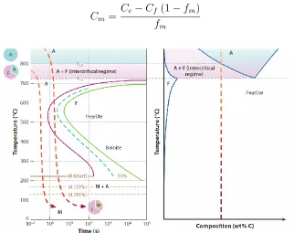
soft ferrite and hard martensite, shown in Fig. 2.2 [10–12]. Martensite carbon content
the DP steel (Cc), carbon content of ferrite (Cf) and martensite volume fraction (fm) as shown in Eq. 2.1.
Cm =
Cc−Cf (1−fm)
fm
(2.1)
Figure 2.2: Schematic diagram of heat treatment methods to obtain dual phase steels
(A: austenite, F: ferrite, M: martensite, Ac1: austenite formation temperature, and
Ac3: ferrite to austenite transformation completion temperature) [12]
Changing the mentioned thermomechanical process will result in the production of
various grades of dual phase steels with different microstructural properties in terms of
martensite volume content and morphology, ferrite grain size (as shown in Fig. 2.3-2.4)
and mechanical properties [7, 9, 13]. In addition to ferrite and martensite, a small
amount of retained austenite may exist in DP steels which reduces the amount of
martensite volume fraction. The effect of ferrite and martensite content and their
morphology on the mechanical properties and deformation behaviour of DP steels have
been extensively studied by different researchers [14–19]. It is shown that the ferrite
is continuous for many DP steel grades up to DP780, however, when the martensite
volume fraction exceeds 50%, the ferrite becomes discontinuous and martensite islands
tend to form a semi-continuous band at the mid-thickness of the sheet [13, 20]. Different
steel are the main responsible sources of developing such microstructural banding
in low-alloy steels [21–23]. Usually, these microstructural bands are not produced
during hot rolling and they can be eliminated by high temperature homogenization
before intercritical annealing to redistribute alloying elements [23, 24]. DP steels
generally show low yield strength and high ultimate tensile strength, continuous
yielding behaviour, high strain hardening rates at low strain values and large uniform
elongation [3, 25].
(a) (b) (c)
Figure 2.3: Thermomechanical procedures to obtain dual phase steels with (a) coarse,
(b) fine and (c) ultra-fine grain size. Ar3: non-equilibrium transformation start
temperature, Pf: pearlite transformation finish temperature, and ε: logarithmic
equivalent plastic strain [7]
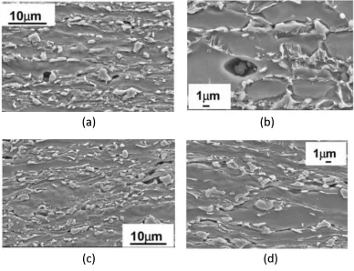
(a) (b) (c)
Figure 2.4: Microstructure of a dual phase steel with (a) coarse grain (CG), (b) fine grained (FG) and (c) ultrafine grain sizes (UFG) achieved by thermomechanical treatment illustrated in Fig. 2.3 showing ferrite (black) and martensite (grey) [7]
The application of dual phase steels is rapidly growing in the automotive sheet metal
forming industry. Usually, conventional low strain-rate processes such as stamping or
roof bows, B-pillar reinforcements, rear side members, and front floor cross members
[26, 27]. However, new high strain-rate forming techniques based on explosive forming
(EF) and electro-hydraulic forming (EHF), which can increase metal formability and
uniform strain distribution and decrease usual forming defects [28, 29], are generating a
great interest in the automotive industry. Experimental research has shown remarkable
improvement in the formability of DP500, DP600, DP780 and DP980 steel sheets that
were formed using an electrohydraulic deformation process [30, 31]. Determination of
metal formability as well as the onset of localization, instability and failure have become
a great interest, yet challenging subject, in both academia and industry. Since limit
strains may be preceded by little diffuse or localized necking, a quantitative prediction
of the limiting strain therefore requires precise and comprehensive assessment of both
necking and failure [32]. Accordingly, the concept of a forming limit curve (FLC) in
principal strain space, initially proposed by Keeler and Backofen [33], and Goodwin
[34], has been extensively used by both academia and industry to evaluate the
quasi-static formability of different dual phase steels [6, 35–38]. Moreover, Maris et al. [39]
derived the high strain rate FLC of DP600 using electrohydraulic free forming (EHFF).
Figure. 2.5 shows two examples of the FLC of DP600 that were obtained based on
(a)
(b)
Figure 2.5: Forming limit diagram (FLD) of DP600 obtained in (a) quasi-static
condition (open circles are necked data points, η is triaxiality andβ denotes strain
Three stages are identified in the work hardening process of DP steels [40, 41]. In the
first stage, ferrite grains are deformed homogeneously in the vicinity of martensite
islands which is considered as the initial work hardening stage. The second stage
consists of limited deformation of the ferrite in the presence of rigid martensite and
the third stage occurs when the dislocation density increases and cell structures form
due to high strain levels. It has also been shown that a small amount of martensite
plasticity can participate in the deformation process in this stage [20].
It has been shown by several researchers that the predominant damage mechanism
and failure in DP steels depends on the ferrite and martensite grain sizes and their
morphology [7, 42, 43], and can change from a mixture of cleavage and dimples to
a completely ductile failure mechanism which consists of nucleation, growth and
coalescence of voids during the forming process [7, 43]. Numerous investigations have
provided detailed analyses of the microstructure and failure mechanisms in dual phase
steels as a function of deformation process parameters (such as strain, strain rate and
temperature) and microstructural properties (such as grain size, martensite content
and morphology) [7, 30, 38, 44–52]. Different mechanisms and potential sites can be
involved in the formation of voids in the diffused necking area, as shown in Fig. 2.6.
One of the mechanisms of void formation is nucleation in cracked martensite, particles
usually when the DP steel contains coarse martensite particles (Fig. 2.6a); inclusions
are also important sites for void nucleation (Fig. 2.6b); the dominant mechanism
is, however, decohesion at the ferrite-martensite interface (or at triple junctions)
(Fig. 2.6c); and finally, void nucleation and also coalescence can take place by the
Figure 2.6: Potential sites for void formation or damage initiation in dual phase steels (DP600), (a) fracture of martensite, (b) decohesion of the interfaces between the martensite particles and the ferrite matrix or at the triple junctions, (c) void initiation between two martensite particles along the grain boundary and (d) voids growth along the ferrite grain boundaries and parallel to the direction of the applied tensile load [48]
Another important factor which determines the dominant fracture mechanism in DP
steels, is the grain size due to the dislocation locking and the formation of Cottrell
atmospheres and relaxation of internal stresses. Indeed grain size is known to have an
effect on the uniform and total elongation of the material [7]. As it can be seen in
Fig. 2.7a, the dominant mechanism of failure in a coarse grained DP steel is brittle
fracture, identified by well-defined facets and cleavage steps on these facets although
a number of dimples can also been observed. The fracture in a fine-grained steel is a
combination of both ductile and brittle fracture, while the ultra-fine grain DP steel
(a) (b)
(c)
Figure 2.7: Fracture surface of tensile specimens indicating an increase in non-uniform
deformation with decreasing grain size in (a) coarse-grained (12µm) and (b) fine-grained
(3µm) and (c) ultra fine-grained (1.5µm) DP steel[7, 51]
Furthermore, Samei et al. [38] showed that strain path also has significant effect
on the damage and fracture behaviour of fine-grained DP steels where shearing can
contribute to severe elongation of dimples on the fracture surface, and shear fracture
can lead to quasi-cleavage fracture, i.e. cleavage surfaces surrounded by dimples, as
Figure 2.8: Fracture surfaces and formation of grooves (G), shear (S) and quasi-cleavage fracture (Q) on DP600 in (a) uniaxial tension and (b) biaxial tension [38]
2.2
Phenomenological damage models
The micro-scale deformation of dual phase steels is complex but at the macro-scale, it
can be considered as a continuum. In continuum damage mechanics, the macroscopic
response of materials is a global response of the material with its various constituents
and defects. Phenomenological damage models usually assume an evolution of a
phe-nomenological parameter based on homogenized variables like deformation gradient or
velocity gradients to simulate materials behaviour. These models are computationally
efficient and due to their relative simplicity, they are more widely-used in industrial
applications [53].
2.2.1
Johnson-Cook model
Johnson and Cook [54] proposed a phenomenological damage model to predict the
critical fracture strain as an extension to Hancock and Mackenzie’s [55] model as
a function of equivalent plastic strain (εp), strain rate ( ˙εp), temperature (T) and
stress triaxiality (η). The JC progressive damage model considers that the damage
process, as shown in Eq. 2.2a, and accelerates sharply when the damage increases over
a critical value [56, 57]. Dis defined as the damage variable and can change from 0 to
1 (Eq. 2.2b) which shows no damage and fully damaged material element, respectively
[56–58]. After the damage commences, the material stiffness and consequently, the
load bearing capacity of the element decreases progressively until the final material
failure. The relation between the accumulative damage parameter (D), equivalent
plastic strain (εp) and critical plastic strain at the final fracture (εf) is given by:
D=X∆εp
εf
(2.2a)
˙
D =
0 if εp < εd
Dc
εf −εd
if εp ≥εd
(2.2b)
where ˙D,Dcandεdare the damage rate, critical damage variable and damage threshold
strain, respectively. The general expression for the equivalent plastic strain at the
onset of damage in the JC model [54, 57, 58] is written as follows:
εf = [D1 +D2exp(D3η)] "
1 +D4ln
˙
εp ˙
ε0 !#
[1 +D5T∗] (2.2c)
where D1...5 are material dependent constants which need to be determined based on
the dynamic behaviour of the material. ε˙0 and T∗ are a reference strain rate and
the homologous temperature, respectively. This fracture criterion is implemented
in most of the well-known commercial finite element simulation software such as
ABAQUS and LS-DYNA [58, 59]. This damage model was extensively utilized and
reported in the literature to simulate the forming and damage behaviour of different
engineering materials: Gillard et al. [28] and Hassannejadasl et al. [29] used it to
evaluate the forming and damage behaviour of dual phase steels subjected to
electro-hydraulic free forming (EHFF) and die forming (EHDF); the performance of this
model as a phenomenological damage model and the Gurson-Tvergaard-Needleman
![Figure 1.1: Application of DP steels in a typical automobile [12, 13]](https://thumb-us.123doks.com/thumbv2/123dok_us/1377789.1170468/28.612.112.539.297.566/figure-application-dp-steels-typical-automobile.webp)


![Figure 2.5: Forming limit diagram (FLD) of DP600 obtained in (a) quasi-staticcondition (open circles are necked data points, η is triaxiality and βdenotes strainratio) [38] and at (b) high strain rate subject to EHFF [39]](https://thumb-us.123doks.com/thumbv2/123dok_us/1377789.1170468/42.612.181.467.66.630/figure-forming-obtained-staticcondition-circles-triaxiality-bdenotes-strainratio.webp)
![Figure 2.7: Fracture surface of tensile specimens indicating an increase in non-uniformdeformation with decreasing grain size in (a) coarse-grained (12(3µm) and (b) fine-grainedµm) and (c) ultra fine-grained (1.5µm) DP steel[7, 51]](https://thumb-us.123doks.com/thumbv2/123dok_us/1377789.1170468/45.612.114.538.71.434/figure-fracture-specimens-indicating-increase-uniformdeformation-decreasing-grainedum.webp)
![Figure 3.4: Numbering and properties of CA neighbouring cells [23]](https://thumb-us.123doks.com/thumbv2/123dok_us/1377789.1170468/97.612.116.531.70.452/figure-numbering-properties-ca-neighbouring-cells.webp)
![Figure 3.5: Self-closing boundary condition of a cell in the corner and its 26 neighbours[23]](https://thumb-us.123doks.com/thumbv2/123dok_us/1377789.1170468/98.612.203.445.71.318/figure-self-closing-boundary-condition-cell-corner-neighbours.webp)