18th International Conference on Structural Mechanics in Reactor Technology (SMiRT 18) Beijing, China, August 7-12, 2005 SMiRT 18-F08-6
DESIGN VERIFICATION FOR REACTOR HEAD REPLACEMENT
Keshab
K.
Dwivedy
Melvin
S.
Whitt
Dominion, Glen Allen, VA, USA
Dominion, Glen Allen, VA, USA
Phone:804 273 3098, Fax:804 273 3448
E-mail [email protected]
Robert Lee
Dominion, Glen Allen, VA, USA
ABSTRACT
This paper outlines the challenges of design verification for reactor head replacement for PWR plants and the program for qualification from the prospective of the utility design engineering group. This paper is based on the experience with the design confirmation of four reactor head replacements for two plants, and their interfacing components, parts, appurtenances, and support structures. The reactor head replacement falls under the jurisdiction of the applicable edition of the ASME Section XI code, with particular reference to repair/replacement activities. Under any repair/replacement activities, demands may be encountered in the development of program and plan for replacement due to the vintage of the original design/construction Code and the design reports governing the component qualifications. Because of the obvious importance of the reactor vessel, these challenges take on an added significance. Additional complexities are introduced to the project, when the replacement components are fabricated by vendors different from the original vendor. Specific attention is needed with respect to compatibility with the original design and construction of the part and interfacing components. The program for reactor head replacement requires evaluation of welding procedures, applicable examination, test, and acceptance criteria for material, welds, and the components. Also, the design needs to take into consideration the life of the replacement components with respect to the extended period of operation of the plant after license renewal and other plant improvements. Thus, the verification of acceptability of reactor head replacement provides challenges for development and maintenance of a program and plan, design specification, design report, manufacturer's data report and material certification, and a report of reconciliation. The technical need may also be compounded by other challenges such as widely scattered global activities and organizational barriers, which must be negotiated. This paper does not describe the massive efforts required by the NSSS and manufacturer’s engineering groups nor does it include the challenges of construction in development of mechanical handling of heavy and large components, or the effort for providing adequate access for the head replacement and restoring the containment structure. The paper outlines the analysis and design efforts needed to support reactor head replacement. The paper concludes that the verification efforts performed by the utility design group not only provide increased assurance of design adequacy, but also serves as an important player on the strong team that is required for a successful head replacement.
Key words:Reactor Head, Repair/Replacement, Alloy 600, Alloy 690
1. INTRODUCTION
Replacement of PWR reactor head were initiated in the industry due to CRDM penetration cracking, which could challenge the reactor coolant pressure boundary and could be postulated to potentially cause a rod ejection accident. In some plants, the engineers took the opportunity to replace the CRDM upper structure, head radiation shield, ventilation shroud and ducts, and the rod ejection missile shield in an integrated package to simplify head lifting and reinstallation during refueling outage. The reactor head replacement is complex in comparison to other routine repair/replacement activity due to the importance of the component, and because of its size and weight. The replacement has to achieve qualification of the entire vessel and its interface structures with respect to design and licensing basis. In addition, modification has to be implemented to mitigate the problem associated with the CRDM weld cracking. A well coordinated effort with in-house engineers, original NSSS vendor, reactor head vendor, and other construction group resulted in a successful completion of four reactor head replacement which is described below.
2. BACKGROUND
Service degradation of reactor vessel head penetrations, such as control rod drive mechanism (CRDM) nozzles, is an evolving aging management issue for PWR plants associated with primary water stress corrosion cracking (PWSCC) in Alloy 600 components and related Alloy 182 and Alloy 82 weldments. This type of SCC is a function of temperature, level of applied stress at the location, and the residual stress, in addition to the component being in contact with the primary water. The phenomenon was identified in 1990s and became a major problem for reactor vessel head when through-wall cracking and leakage were identified in penetration of a number of plants. Unlike other materials, there is no established standard to accept a small identified flaw in this material without detailed inspection, evaluation and/or repair. Prior to identification of problem in 1992 there were no readily available crack growth rate (CGR) data, which is essential for predicting remaining life of degraded component.
Certain crack growth models have been subsequently developed. EPRI [5,9] material reliability program (MRP)
recommended CGR equation developed from screened laboratory data adjusted for the temperature. The data covered a range of temperature of the reactor head. An international panel of expert reviewed the data and made recommendations. In the 1990s, a number of foreign utilities had proactively initiated programs to replace their reactor heads.
US Nuclear Regulatory Council (NRC) issued two bulletins[10,11] and one enforcement action[12] in early 2002 to require US utilities to conduct bare head visual inspection of the reactor vessel head and conduct volumetric NDE examinations of CRDM penetrations; if defects were identified, perform evaluation of acceptable remaining life, or perform repairs. One US plant had significant damage to the head base metal resulting from the leak of boric acid through a cracked CRDM penetration, which was overlooked and not identified during earlier inspections. Clear focus on aging management of the CRDM penetrations of the four Dominion Virginia plants (Surry 1 and 2, North Anna 1 and 2) started in 1994 when detailed augmented inspection was conducted on one of the units. Visual examination and sample eddy current examination was conducted on a limited number of CRDM penetrations of North Anna Unit 2 and no signs of degradation was identified. As a follow up action, North Anna Unit 2 and Surry Unit 1 reactor vessel heads were inspected in fall 2001. In the Surry Unit 1 inspections, eddy current (ECT), ultrasonic (UT), and liquid penetrant (LP) inspections were conducted in addition to bare head inspection. Weld cracking was identified at 10 locations. The flaws in four out of ten were removed by excavation and grinding. The other six had rejectable indications and were repaired by temperbead weld repair. Similar fall 2001 inspection at North Anna Unit 2 showed cracking at seven penetrations; for four of the penetrations, conservative crack growth calculations determined that end of life (i.e. through-wall cracking) could not occur before re-inspection at the next refueling outage. The unit was restarted. The other three were repaired using Westinghouse embedded flaw[7] weld repair. These repair efforts were costly both in dollars and dose. Concurrently, plans were developed to replace all four reactor heads in an organized manner between 2004 and 2006 to avoid dose and cost associated with future NRC-mandated inspections.
In the fall 2002 outage at North Anna Unit 2, a large number of indications were identified in the penetrations, mostly in the weld buttering. Indications were also found in three of the penetrations repaired during the previous outage. Many of the small indications were identified due to improved inspection technique; the cracking in the repaired penetrations was attributed to inadequate implementation of a qualified repair process, as discussed in Reference [7]. But the cracking was extensive, and the dose and cost associated with a qualified inspection and repair was considered prohibitive. The head was to be replaced the following outage. It was estimated that repair of the existing head could require up to 1000 man-rem; cost of the repair was estimated to be on the same order as actual head replacement. All options were considered. The Dominion team knew that Framatome had at least one vessel head available in France fabricated using the Alloy 690 tubes and alloy 152/52 welds for penetrations. The Dominion team spent a mere five days assessing information to determine whether they could make the French head work. Despite the technical challenges apparent, the decision was made to replace the head,
rather than expending the dose and costs for repair, only to replace the head 18 months later. When the decision was made, the NRC described it as “a significant step forward for nuclear safety,” and agreed to expedite reviews to verify acceptability.
As a result, the entire reactor head replacement project was accelerated to replace the heads of the four plants in consecutive refueling outages, starting with North Anna 2, already 30 days into the refueling outage. This would be followed by North Anna Unit 1, then Surry Unit 1, and Surry Unit 2 in a tight schedule. The first three units would use heads provided by Framatome from France; those European plants could defer their planned head replacement until other heads were fabricated. For Surry Unit 2, the first of the heads previously ordered from Mitsuibishi would be available.
The first three reactor heads had already been fabricated for three 3-loop Westinghouse PWR plants in France. The available heads were designed, fabricated and inspected to French Codes, specifications, quality assurance and standards. Even though the material, design configuration, and loadings had a lot of similarities, the components were required to meet ASME Code, Dominion design specification, quality assurance and regulatory review. In addition, the component has to properly interface with other components and has to avoid interference with other areas of the plant during installation. There were enough differences between the existing heads and the newly available heads to make the evaluation of interface components highly demanding. Due to the proactive nature of Dominion’s head replacement activity to enhance nuclear safety, the US NRC regulators agreed to participate in accelerated review of design and inspection of components. The accelerated project schedule brought additional challenges to design, fabrication and installation of the reactor head and its associated components. For example to expedite the first head replacement, the head was flown from France to Richmond, Virginia aboard a Russian cargo airplane, one of the largest aircraft in the world.
Unfortunately, the heads would not pass through the containment equipment hatch. Therefore, Bechtel was contracted to provide the engineering and equipment to cut a temporary access opening in each of the four containments for the head, and then to rig and transport the old heads out of containment and the new heads into containment. Then the access opening was repaired to original strength.
Ultimately, the team would have to work on three continents, in three different languages, with six different companies, and two different vessel codes.
The experience gained from engineering verification of design is discussed in the remaining sections.
3. REPLACEMENT PROGRAM AND PLAN
ASME Section XI is very specific about development of a replacement program and plan. As required by the Code, administrative control was placed with a project director and a group of managers for the entire term of the project. NSSS component supply organization was identified and were given responsibility of managing the work of manufacturer’s design and fabrication activity and an AE firm was identified to perform installation. Specifications were developed for the replacement head and other associated components and structures, which identified applicable codes and standards, description of work to be performed, applicable weld procedure, heat treatment, nondestructive examination, tests, and material requirements. The intended life of replacement items was also identified. The replacement program plans and the required evaluations were reviewed by regulatory authorities. The program was setup for verification of the replacement component for acceptability. Since the replacement was initiated for cracking of CRDM penetrations, the program was set up to change the material and welding of CRDM tubes which had superior resistance to stress corrosion cracking. Consistent with the Code requirements, certified design specification, certified design stress reports, manufacturer’s data reports and material certifications were set up to be maintained for the effort and the existing reports, specifications affected by the replacement were also set up to be updated
.
4. CONFIGURATION OF THE REPLACEMENT HEADS
The configurations of the new reactor heads for the first three replacements North Anna Units 2 and 1 and Surry Unit 1 were largely identical to the original heads with the following exceptions.
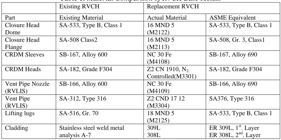
• The replacement heads had been fabricated in accordance with the 1993 Edition of the French RCC-M Code
with 1st, 2nd, and 3rd Addenda. In accordance with ASME Section XI IWA 7210, a reconciliation report was developed establishing the acceptability of the replacement head. A comparison of the materials used in the new head vs. the old head is provided in Table 1
• The inside dome radius is 22 mm larger than the existing, but the cladding is 3 mm thicker, resulting in a net
increase in radius of 19 mm. However, due to other minor dimensional differences, the internal volume is
actually decreased by a very small amount, 1.8 ft 3, or about 0.02%. Analyses confirmed that this small
difference had only a small, and acceptable, effect on the LOCA accident analyses. Effects on non-LOCA
accident analyses were negligible.
• In the new French heads, the CRDM tubes are friction welded to the CRDM housing flanges. Because the
ASME code does not recognize the continuous drive friction welding technique, an evaluation was prepared by
Framatome toevaluate and justify the acceptability of friction welding the CRDM nozzle housing and adapter.
• The reactor head flange is approximately 100 mm thicker than the existing flange, increasing the weight and
reducing the head stud projection. The impact of the weight increase required dynamic analyses to demonstrate acceptability, as discussed in a later section of this paper. The smaller stud projection required modification of the reactor stud tension equipment. In addition, although the closure force on the studs does not change, the stud elongation will be greater due to the thicker head flange.
• The O-ring grooves on the replacement head are slightly larger (by 3 mm) than those on the existing RVCH.
The groove depths are also different (2.7 mm deeper). Therefore, new O-rings had to be procured.
• The three lifting lugs are located at different locations (about 50 mm smaller radius, and 18o offset from the current location). This difference in lug location was resolved by use of an intermediate ring connected to the lugs on the head below and to the columns of the head lift leg above (see Fig.3). This lifting ring resulted in additional increased weight, and interferences with other structures on the head which had to be resolved. These issues are discussed more in a later section of this paper.
• The CRDM nozzle housing configuration was essentially the same; however, the numbering of the nozzles was
different and had to be accounted for. The connection configuration of the replacement RVCH CRDM nozzles is similar to the existing RVCH with the exception of the CRDM nozzle-housing adapter.
• The location of the nozzles for the reactor vent line and the reactor vessel level inventory system (RVLIS) are
different on the replacement head, requiring local rerouting of the vent line and RVLIS piping.
• Reactor Vessel Vent Line was relocated due to interferences and had to be analyzed.
• CRDM Supports were kept essentially same. The horizontal struts supporting seismic and LOCA loads were
kept as is. The vertical support continued to be provided by the lift leg, but the end condition of the lift leg was altered because the load path went through the intermediate lift ring.
• RPV Head Radiation Shield: The existing radiation shield could not be used because those could not be
attached to the head lift lugs, and was attached by clips connected to the intermediate lift ring.
• RPV Head Cooling Shroud and Ductwork attachment were redesigned to avoid interference with the lift ring.
A number of the issues identified for the three French heads will be discussed in a later section.
The replacement head for Surry Unit 2 was the head originally ordered for North Anna Unit 1, and fabricated by Mitsubishi Heavy Industries in Japan. This head was nearly identical to the original Surry head (other than use of the Alloy 690 for CRDM penetrations); however, some of the penetrations were relocated. In addition, Surry Unit 2 installed replacement CRDMs and the Westinghouse-designed Head Assembly Upgrade Package (HAUP) modifications. This integrated package serves as reactor head radiation shield, CRDM cooling shroud, and missile protection for rod ejection, and provides easy access for assembly and disassembly of electrical and control cables. The HAUP modifications were designed to simplify the future disassembly / reassembly process, reducing future outage time. The HAUP modifications required a number of additional analyses, as discussed in a later section of this paper.
Table 1. Material Comparison of RVCH Base Metals
Existing RVCH Replacement RVCH
Part Existing Material Actual Material ASME Equivalent
Closure Head Dome
SA-533, Type B, Class 1 16 MND 5
(M2122)
SA-533, Type B, Class 1
Closure Head Flange
SA-508 Class2 16 MND 5
(M2113)
SA-508, Gr. 3, Class1
CRDM Sleeves SB-167, Alloy 600 NC 30 Fe
(M4108)
SB-167, Alloy 690
CRDM Heads SA-182, Grade F304 Z2 CN 1910, N2,
Controlled(M3301)
SA-182, Grade F304
Vent Pipe Nozzle (RVLIS)
SB-166, Alloy 600 NC 30 Fe
(M4109)
SB-166, Alloy 690
Vent Pipe (RVLIS)
SA-312, Type 316 Z2 CND 17 12
(M3304)
SA376, Type 316
Lifting lugs SA-516, Gr. 70 18 MND 5
(M2125)
SA-533, Type B, Class 1
Cladding Stainless steel weld metal
analysis A-7
309L 308L
ER 309L, 1st. Layer ER 308L, 2nd. Layer
5. APPLICABLE CODE
The original reactor vessel including the head had been furnished per the requirements of Westinghouse specification and was designed and fabricated in accordance with the ASME Code Section III, 1968 Edition including Addenda through 1969, but was not ASME code stamped. The replacement reactor vessel closure head (RVCH) was to be furnished as a replacement part of the reactor vessel under ASME Section XI. The replacement RVCH is not code stamped but to the extent possible is designed and fabricated in accordance with the ASME Boiler and Pressure Vessel Code, Section III, 1995 with Addenda through 1996. The Code reconciliation was performed to the requirements of ASME Section XI Code for component replacement. The reconciliation process was a two step process for the three heads designed to RCCM Code. The replacement head designed and fabricated to RCCM Code was first reconciled with the later version of the ASME Code and then to the original design code. The interface components were treated with their vintage material properties, inspection and testing. The exceptions identified during the reconciliation process were recorded and resolved by additional analysis.
6. LOADING CONDITIONS
The specified loadings on the replacement head and the interface components contained Design, Normal/Upset (Level A/B), Emergency (Level C), Faulted (Level D), and Test Conditions similar to the original design specification. Design loading consisted of dead weight, operating basis earthquake (OBE), design pressure of 2485 psig, and design temperature of 650oF. The increase in dead weight due to intermediate lift ring and increased head weight has to be accounted in upper structure for both lifting and integrity of the support during operation. The normal loading consisted of 200 events of plant heat-up and cool-down; 18300 events of plant loading and unloading at 5% per minute; 2000 events of 10% step load increase and 10% step load decrease; 200 events of large step load decrease; 10 events of turbine roll test; and an infinite number of steady state fluctuations. The upset conditions included 80 events of loss of load; 40 events of loss of power; 80 events of loss of flow; 400 events of reactor trip from full power; and 400 cycles of OBE loading due to 20 OBE events. Two faulted conditions were specified -- one event of design basis earthquake (DBE) with pressure loading of 2485 psig; and one event of steam line break at 555oF. Test conditions specified were five events of pre-start-up primary side hydrostatic test at 3105 psig; and 50 events at 2485 psig in service. The test conditions were specified to be included in the component
fatigue analysis in addition to normal/upset loadings. No emergency condition loading wasspecified.
The design, faulted and test conditions remained the same as the original reactor head. The specified temperature and pressure transient loadings for normal/upset operating conditions had been altered over time due to plant modifications and core up-rates. It may have been routine to design the replacement component for the specified loading, but these changes made the reconciliation with interface components demanding. The loss of coolant accident (LOCA) (a faulted load) was not specified for the design of the RVCH. However, the LOCA and seismic analysis had to be re-performed for the reactor vessel assembly with the reactor internals, vessel support, and upper structures in order to verify that the marginal increase of head weight and the required changes to the upper structures did not invalidate previous seismic and LOCA analyses. Therefore, new seismic and LOCA loads were generated for design verification of:
• Reactor Internals,
• Vessel Support and Neutron Shield Tank,
• Reactor Vessel Head Intermediate Lift Ring,
• Head Lift Leg (Column),
• CRDM Platform and Support Structures,
• Head Ventilation Structure,
• Head Radiation Shield,
• Reactor Vessel Level Instrumentation (RVLIS) Piping, and other items attached to the reactor head.
In the original design, most of these components were qualified to Large Break LOCA in a generic manner, based upon certain bounding evaluations. Elimination of large break LOCA by use of leak-before-break (LBB) analyses had been used to remove a number of snubbers from the NSSS support system at both plants. Certain components had been evaluated to applicable small break LOCA appropriate for the components; those evaluations were either for a design change or for certain operational changes. In most of those situations, the evaluations were generic evaluations by the NSSS vendor, covering many plants. Consequently, very little plant specific analysis, force time history or equivalent static LOCA load was readily available for defining applicable LOCA loads. These loadings had to be developed for component qualification. In addition to the vintage issues on the loading, there was
also similar challenge for load combinations, when one set of load is specified by force time history and other
dynamic load is a static equivalent
.
7. CODE STRESS AND FATIGUE EVALUATION OF REACTOR HEAD
Detailed stress analysis and fatigue evaluation were required for the closure at the flange, the weld joint at CRDM penetration, the vent line weld location at the head (See Figure 1) and the welded attachment for the head lifting lug. Framatome performed the analysis for the three heads obtained from France, while Westinghouse performed the analyses for the fourth head. In addition to conventional design verification performed by these vendors, Dominion’s in-house engineering group performed the verification of calculations and stress reports. In addition, the design verification was performed for various other interface components.
The closure head consists of a hemispherical shell welded to the head flange. The head accommodates 65 CRDM adapters and the vent pipe. The head flange contains 58 holes for the closure studs and the vessel flange contains 58 threaded holes and is welded to the main nozzle shell course. The studs are tensioned between flanges to ensure proper sealing with the pair of O-ring gaskets. The outer gasket is assumed to provide a leak-tight seal. Equivalent stiffnesses of the adapter perforations, studs and associated holes were used to construct a two-dimensional axisymmetric model for thermal analysis. In the head flange model, allowance was made for stud and adapter holes by adjusting the modulus of elasticity and Poisson’s ratio. Pressure, temperature transients, and stud tension loadings were considered. The variation of stud tensioning under normal/upset conditions was accounted for by considering head and vessel flange displacements. The existing studs were re-used with the new heads, but new stress analysis for the stud was performed to assess the bolting stress variation under normal/upset and during hydrostatic tests. The peak root stresses for the fatigue analysis are calculated using appropriate stress concentration factors.
The adapter tubes for the CRDMs, vent pipes, and spares are shrink fitted through the wall of the head and are welded near the inside surface of the closure head with J type weld. The tube has a flange at the upper end. The configuration of the weld changes depending upon the distance of the penetration from the head centerline as the penetrations move down the “hill-side” of the dome. An axisymmetric finite element model was used in the analysis; the model included the adapter tube, the weld and a portion of the closure head. A 3-D model was analyzed for the actual geometry of a sample peripheral penetration to develop a correction factor to address the “hill-side” non-symmetry. The correction factor was then applied to the stresses obtained from the axisymmetric model. The pressure and temperature transient loading was considered to be the same as the transients for the reactor coolant hot leg. The seismic and other external loads were applied from the CRDM upper structure analysis. A stress concentration factor of 4.0 was applied on the linearized stress across the weld to determine the discontinuity stress
at the root of the weld for fatigue analysis. An axisymmetric model was used for vent pipe connection which is the
center of the head. The applied loading on the model were taken from piping analysis; the transient loading used was the same as for the CRDM penetrations.
The head lifting lugs are considered as a part of pressure boundary; Bijlaard’s method was used to calculate local stress at the lugs.
As indicated above, Dominion performed a review of the calculations and stress reports for the heads. This review was primarily to ensure clarity of the documentation and proper transfer of design inputs between organizations.
8. SUMMARY OF CODE COMPLIANCE CHALLENGES FOR OTHER COMPONENTS
Reactor Internals
The reactor internals were not directly impacted by the head replacements. However, the head replacements did increase the weight of the head and to a small extent, the distribution of mass in the upper structure. This required seismic and LOCA dynamic analysis to verify that the weight increase did not significantly affect the dynamic response of the head, which could feed back into the reactor internals analysis. The analyses confirmed that the reactor internal structural response was not significantly affected.
Reactor Vessel Support and Neutron Shield Tank
Because the weight of the head increased, it was necessary to perform new seismic and LOCA analyses of the Reactor Vessel support. Previously a large number of snubbers had been removed from the RC loops and Steam Generators using Leak-Before-Break (LBB) to eliminate large-break-LOCA. In addition at Surry, additional snubbers have been eliminated using NRC Generic Letter 87-11 to eliminate arbitrary intermediate breaks in Main Steam lines. For the analysis associated with these snubber eliminations, the reactor nozzle had been taken as fixed points; because the loads were enveloped by previously postulated large-break LOCA loads, it had not been necessary to review the reactor vessel support loads. Now, however, the loads had increased and the supports and Neutron Shield tank below had to be reviewed. Seismic and small-break LOCA analyses were performed. The LOCA analyses were conservative since the support loads were taken as the maximums from the resulting
history analysis, then applied simultaneously as static loads. These loads were reviewed based on existing design calculations, and demonstrated to be acceptable.
For Surry, which had been designed a number of years earlier, no small-break LOCA analyses had been performed, since it was obvious that they would be enveloped by the large-break LOCA loads. However, it was now necessary to perform these analyses. The reactor support stiffnesses for Surry were compared to those used for North Anna, and determined to be sufficiently similar that, the same time-history for North Anna could be conservatively used for Surry. However, the result of several layers of conservatism in these analyses was that the
newly calculated smallbreak LOCA design loads were on the same order of magnitude as the previous large-break
LOCA loads. Review of the reactor vessel supports concluded they were acceptable; the Neutron Shield Tank was almost identical to the corresponding North Anna tank, and was similarly concluded to be acceptable.
Head Lift Assembly/CRDM Support Structure
These auxiliary components and structures on the reactor head, including the head lift assembly and CRDM support structure were impacted in two different ways.
(1) For the first three units, the French replacement heads had the lift lugs in a different location from the existing heads, located at an angle of 18 degrees around the circumference. To resolve this problem, an intermediate lift ring was designed, based on a similar one previously used at a French plant. While this resolution permitted the use of the head, it required redesign of the attachment of the auxiliary structures and components. In most cases, new components were fabricated, based on previous drawings to avoid potential interferences, and modified for new attachments, etc. This required new drawings, and development of calculations to demonstrate adequacy.
(2) For the last unit, Surry Unit 2, the head did not require an intermediate lifting ring, but the HAUP required changes to these structures. Therefore, different design constraints required different changes. Because other utilities may also be considering implementing installation of a HAUP or similar integrated upper structure, these changes will be discussed in some detail.
The head lift assembly consists of the removable tripod that attaches to the upper support structure, and the three support columns which are attached to the reactor head and also support the CRDM upper support platform. These three columns have pinned connections to the three lugs on the reactor head, and rigid connections to the upper platform structure (see Figure 2). The radiation shield is a cylindrical ½”-thick steel wall around the head which was attached to the head at the three lugs; hinged doors permit entry during outages, and there are cutouts for access to valves, etc. On the French heads, the three lifting lugs are similar, but are in different locations, rotated 18 degrees around the head. This required installation of an intermediate lifting ring to accommodate the offset, as shown in Figre 3. The ring itself was fabricated from the 14’-diameter flange available from another component. Two adapter blocks and a pin were used to connect the lower face of the ring to each lug on the head. An adapter block was used on the top face of the ring to provide a rigid connection for the lift column (leg).
The installation of the ring obviously required reanalysis of the load path for lifting the head, which had to meet NUREG-0612 criteria. Less obvious is the fact that because the lift assembly also serves as part of the support for CRDM assembly platform and other items on the reactor head during plant operation, reanalysis of the CRDM support structure was required because of change in upper structure load path through the ring. A coupled non-linear dynamic analysis was required for both seismic and LOCA loading because of gapped plates at CRDM support platform. The analysis also necessitated review of struts (Fig.2) which provides lateral restraint to the CRDM platform during seismic and LOCA events, and of the anchorage of the struts to the building structure.
In addition, the intermediate lift ring necessitated relocation of the radiation shield, which was redesigned, and now sits on the intermediate lift ring, attached by clips around the circumference.
Missile Shield
For all four plants, the original CRDM missile shield was an independent structure supporting 2-foot thick concrete blocks over the CRDMs. The missile shield blocks and support structure must be removed early in the outage using the polar crane, and stored throughout the outage. For the first three plants, there was no change. For Surry Unit 2, the HAUP provides an integrated missile shield made of steel plate attached to the three columns of the head lift rig. Missile impact analyses were required to demonstrate adequacy of the shield, the vertical support columns, and the attachments transferring the loads. These missile impact analysis methods had to be consistent with plastic analysis methods cited in the UFSAR or reconciled with previous commitments.
Head Ventilation Shroud Structure
The existing head ventilation system uses three CRDM Fans per unit with the ducts taking suction in the cooling shroud near the head, drawing air downward between the CRDM tube array, directed by baffles, and out and through the ducts to the CRDM fans. The three ducts are attached to the cooling shroud and the shroud and ducts are removed as a unit during outage. Storage of this assembly, known as “the octopus”, has been a space utilization problem during outages. For the first three heads, the general configuration is maintained, but new cooling shrouds were fabricated with new attachments, which had to be qualified. For Surry Unit 2, the HAUP replaces the previous configuration with a new head ventilation system. The new flow path is reversed, with air from the lower area of the cavity entering the shroud near the head, then upward between the CRDM tubes, and out into three ducts at the top of the HAUP, and then to the existing CRDM fans. The three ducts can be removed independently, and storage has much more flexibility. Because of the new flow path, new air flow calculations were required. Also, new temperature monitoring instrumentation is provided at points in the flow path.
The design calculations for these components were reviewed by Dominion’s in-house Engineering Mechanics group. This group also facilitated exchange of information between the two NSSS equipment vendors, and verified that the analyses by the two different groups meshed. A number of design issues were identified during this review. One example was the potential for thermal restraint due to the temperature difference between the reactor head and the intermediate ring which was not in contact with the head. This was resolved by slightly elongating the holes in the lower adapter blocks in the horizontal (radial) direction to accommodate the relative thermal displacement. A second issue was analysis of the intermediate lift ring and, columns and connections for the dynamic response loads from seismic and LOCA loadings transmitted through the head and CRDMs. While the lifting loads clearly governed most components, it was necessary to ensure that the seismic and LOCA loadings were also met. It should be noted that Westinghouse subsequently issued an Advisory Letter [16] warning that this was a possible generic concern. A third example was the issue of the seismic qualification of the personnel bridge to the HAUP, discussed below.
The effort to complete all design provisions for the HAUP was challenging, especially as the project team members working on the HAUP were also the same individuals supporting the other three head replacements. Further, there were a number of unique design features for this plant vs. the plants for which HAUPs had been previously provided. As a result, it required a sustained effort to complete the design integration work and calculations. The “90 / 10 rule” was in force – 10 percent of the items require 90 percent of the work. For example, one of the major benefits of the HAUP was a cable handling system, which permits all the cables to be disconnected at the head end of a “draw-bridge” which is then raised up out of the way for head removal. The same design was used for a personnel access draw-bridge. The cable draw-bridge design worked well. However, the effort to qualify the similar design for the personnel drawbridge structure took a significant amount of work. This was partly because of anchor bolt installations, but also because of an initial misunderstanding of nuclear requirements – the cable “draw-bridge” had to be seismically qualified in the operating (down) position but could be considered as non safety related when it was in the open position during outages. However, the personnel drawbridge did not have to be seismically qualified in the operating down position but did have to be seismically qualified when it was in the open position, to avoid potentially impacting the head during operation. This misunderstanding was not serious, but resulted in removal of part of the personnel bridge structure prior to unit start-up.
While there were challenges for the four head replacements, the collaborations between Dominion, Westinghouse, Framatome, and Mitsuibishi was able to complete the project in remarkable accomplishment of teamwork. The Dominion engineering group is proud to have played a role in this effort.
9. CONCLUSIONS
The analysis work supporting replacement of reactor head required coupled nonlinear dynamic analysis of reactor vessel, reactor internals, vessel support and the reactor head upper support for seismic and LOCA loading.
The reconciliation process lead to qualification of the entire vessel with the internal, vessel support including neutron shield tank, CRDM and CRDM platform, reactor vent and level instrumentation piping, the head radiation shield and ventilation shrouds and ducts.
In a reactor head replacement project, particularly one with a different head manufacturer, there is the clear need to verify calculations, which overlap boundary interfaces. The degree to which the project structure will involve in-house engineering resources will depend upon a number of factors – availability and expertise of in-house staff; use of different suppliers; schedule constraints; retrievability of in-house documentation and calculations; end-user of the calculations prepared; etc. However, the reviewers have to be partners in the project, or they will be more of a hindrance than a help. Our experience was that in-house verification added a level of expertise that helped ensure successful completion of the entire project.
10. REFERENCES
1. ASME Boiler and Pressure Vessel Code Section XI, 1989 Edition.
2. ASME Boiler and Pressure Vessel Code Section III, Div. 1, 1968 Edition with winter addenda through 1969. 3. ASME Boiler and Pressure Vessel Code Section III, Div. 1, 1995 Edition with Addenda through 1996. 4. ASME Boiler and Pressure Vessel Code Section II, Div. 1, 1995 Edition with Addenda through 1996.
5. “Crack Growth and Micro structural Characterization of Alloy 600 PWR Vessel Head Penetration Material;” EPRI December 1997: TR-109136.
6. Psaila-Dombrowski M. J. et al., “Evaluation of Weld Metals 82,152, 52 and Alloy 690 Stress Corrosion
Cracking and Corrosion Fatigue Susceptibility,” Proceedings, Eighth International Symposium on Environmental Degradation of Materials in Nuclear Power Systems- Water Reactors, ANS, 1997.
7. Bamford W. H. et al., “The Embedded Flaw Process for Repair of Reactor Vessel Head Penetrations and its Application at North Anna Unit 2,” ASME PVP-Vol. 463, 2003.
8. Bamford, W. and Boo G. D., “ Background and Technical Basis for the Evaluation of Flaws in PWR Reactor Vessel Head Penetration Regions,” ASME PVP-Vol.480, 2004.
9. “Materials Reliability Program (MRP) Crack Growth Rates for Evaluating Primary Stress Corrosion Cracking (PWSCC) of Thick wall Alloy 600 Materials (MRP-55NP)”, Non-Proprietary Version, EPRI 2002: 1006695NP 10. US NRC Bulletin 2001-01, “Circumferential Cracking of Reactor Pressure Vessel Head Penetration Nozzles”. 11. US NRC Bulletin 2002-1, “Reactor Pressure Vessel Head Degradation and Reactor Coolant Pressure
Boundary”.
12. USNRC EA-03-009, “Issuance of Order Establishing Interim Inspection Requirements for Reactor Vessel Heads at Pressurized Reactors”.
13. USNRC Regulatory Issue Summary 2003-13: Responses to Bulletin 2002-01, Reactor Pressure Vessel Head Degradation at Reactor Coolant pressure Boundary Integrity.
14. US NRC Bulletin 2003-02: Leakage from Reactor Pressure Vessel Lower Head Penetrations
and Reactor
Coolant Pressure Boundary Integrity.
15. Bhavnani D. and Annett J., “Design Issues and Considerations During Reactor Vessel Head Replacement ” ASME PVP-Vol.480, 2004.
16. “Reactor Vessel Head Assembly LOCA loads", Westinghouse Nuclear Safety Advisory Letter, NSAL-05-1, January 2005.