University of Windsor University of Windsor
Scholarship at UWindsor
Scholarship at UWindsor
Electronic Theses and Dissertations Theses, Dissertations, and Major Papers
1-1-1970
Backscattering of light atomic projectiles from thin gold films in
Backscattering of light atomic projectiles from thin gold films in
the energy range 50-110 keV.
the energy range 50-110 keV.
Everett Brimmer University of Windsor
Follow this and additional works at: https://scholar.uwindsor.ca/etd
Recommended Citation Recommended Citation
Brimmer, Everett, "Backscattering of light atomic projectiles from thin gold films in the energy range 50-110 keV." (1970). Electronic Theses and Dissertations. 6847.
https://scholar.uwindsor.ca/etd/6847
This online database contains the full-text of PhD dissertations and Masters’ theses of University of Windsor students from 1954 forward. These documents are made available for personal study and research purposes only, in accordance with the Canadian Copyright Act and the Creative Commons license—CC BY-NC-ND (Attribution, Non-Commercial, No Derivative Works). Under this license, works must always be attributed to the copyright holder (original author), cannot be used for any commercial purposes, and may not be altered. Any other use would require the permission of the copyright holder. Students may inquire about withdrawing their dissertation and/or thesis from this database. For additional inquiries, please contact the repository administrator via email
BACKSCATTERIM6 OF LIGHT ATOMIC PROJECTILES FROM THIN Au FILMS IN THE ENERGY RANGE 50-110 keV
by
E ve re tt Brimner
A Thesis
Submitted to the Faculty of Graduate Studies through the Department of Physics In P a rtia l F u lfillm e n t of the Requirements fo r
the Degree of Master of Science a t the U n iv e rs ity o f Windsor
Windsor, Ontario 1970
UMI Number: EC52789
INFORMATION TO USERS
The quality of this reproduction is dependent upon the quality of the copy submitted. Broken or indistinct print, colored or poor quality illustrations and photographs, print bleed-through, substandard margins, and improper alignment can adversely affect reproduction.
In the unlikely event that the author did not send a complete manuscript and there are missing pages, these will be noted. Also, if unauthorized copyright material had to be removed, a note will indicate the deletion.
UMI
UMI Microform EC52789 Copyright 2008 by ProQuest LLC.
All rights reserved. This microform edition is protected against unauthorized copying under Title 17, United States Code.
ProQuest LLC 789 E. Eisenhower Parkway
APPROVED B Y ;
^ 9 6 5 6 3
ABSTRACT
Thin gold film s , vacuum deposited onto a b erylliu m s u b strate, have been irra d ia te d w ith ,?Li , and p ro je c tile s in the energy range 50-110 keV. The backscatter in te n s ity a t a laboratory s c a tte rin g angle o f 136.4 degrees was measured. The in te n s ity is not e x a c tly proportional to film thickness but increases more ra p id ly . This e f fe c t has been a ttrib u te d to m u ltip le sm all-angle c o llis io n s .
ACKNOWLEDGEMENTS
I wish to thank D r. A. van Wijngaarden fo r his supervision throughout the course of th is work. I should also lik e to thank D r. W. Bay!is fo r suggesting the s h e ll-s h ie ld e d Coulomb p o te n tia l, and Mr. B. Miremadi fo r his valuable assistance during the measure ments.
Acknowledgements are also due to D r. J . P. Marton who measured the thicknesses of the th in gold film s .
I am als o indebted to the National Research Council of Canada fo r its fin a n c ia l support in the form of a Graduate Scholarship.
F in a lly , I am g ra te fu l to my w ife fo r her understanding and encouragement.
11
TABLE OF CONTENTS
ABSTRACT î
ACKNOWLEDGEMENTS ! i
LIST OF FIGURES Iv
CHAPTER 1 - INTRODUCTION I
CHAPTER n - THEORY 3
CHAPTER 111 - EXPERIMENTAL 10
3:1 D etector E ffic ie n c y 10
3 :2 Film Thickness 12
CHAPTER IV - RESULTS 14
4:1 Backscatter of 'h 14
4 :2 Backscatter of ^He, ^Ll and '*B 16 CHAPTER V - ENERGY LOSS IN THE FILM 20 CHAPTER VI - MULTIPLE SCATTERING EFFECTS 25
6:1 Angular Divergence 26
6:2 Correction Factor 27
6:3 Dependence of Backscatter Y ie ld on Film
Thickness 30
CHAPTER V I 1 - DISCUSSION 33
APPENDIX 1 - THE SHELL-SHIELDED COULOMB POTENTIAL 34 APPENDIX I I - THE CLASSICAL CROSS SECTION FOR THE
SHELL-SHIELDED COULOMB POTENTIAL 36 APPENDIX 111 - TRANSFORMATION FORMULAE BETWEEN LAB
AND CM FRAMES 40
111:1 R elationship of the Cross Sections 43 APPENDIX IV - EXPERIMENTAL DIFFERENTIAL SCATTERING
CROSS SECTION 44
BIBLIOGRAPHY 45
VITA AUCTORIS 46
LIST OF FIGURES
1. Various P o ten tials as a Function of In tern u clear
Distance R 7
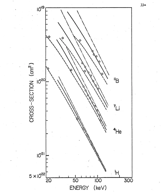
2 . The Energy Dependence of Various Laboratory Cross Sections fo r S catterin g Through 136,4
Degrees of Various P ro je c tile s From Gold 9 , 33a 3 . Schematic Diagram of the Apparatus 11 4 . Energy Dependence of the Observed Backscatter
Y ie ld of 'h From Various Thin Gold Films 15 5 . Energy Dependence of the Observed Backscatter
Y ie ld of ^ From Various Thin Gold Films 17 6 . Energy Dependence of the Observed Backscatter
Y ie ld o f a i From Various Thin Gold Films 18 7. Energy Dependence of the Observed Backscatter
Y ie ld of *'B From Various Thin Gold Films 19 8 . The Nuclear Stopping Power (d f/d ? )n as a
Function of (from Lindhard e t a l . 1963) 22 9 . Correction Factor fo r M u ltip le S c atterin g
as a Function of Evaluated a t H alf the
Film Thickness 29
10. Observed and Corrected Backscatter Y ie ld as
a Function of Film Thickness 31 11. Asymptotic Views of an E la s tic C o llis io n in
the Lab System 40
12* Asymptotic Views of an E la s tic C o llis io n in
the CM System 4 l
13. A Vector A ddition Diagram o f the V e lo c itie s
of P a rtic le s in the CM and Lab Frames 42
iv
CHAPTER 1 INTRODUCTION
The energy loss of atomic p ro je c tile s in solids can be
a ttrib u te d to two separate processes: nuclear reco il and e le c tro n ic e x c ita tio n . In a nuclear c o llis io n the ta rg e t nucleus together w ith
its o rb ita l electro ns re c o ils , and the p r o je c tile is d e fle c te d . In general slow ions lose energy p rim a rily to ta rg e t atoms and t h e ir tra je c to ry consists of a devious path, w hile fa s t ions d iss ip a te energy mainly through e le c tro n ic e x c ita tio n and t r a v e l, th e re fo re , in nearly s tra ig h t lin e s . Although the major energy loss mechanism fo r lig h t
k
atomic p ro je c tile s above about 10 eV is the e le c tro n ic one, some nuclear c o llis io n s occur and backseatt e ring of in cident ions can r e s u lt. At
6 "7
energies above 10 -1 0 ' eV, such in te ra c tio n s are almost purely Coulomb!c fo r the lig h te s t atomic p r o je c tile s , and the s c a tte r in g ,
th e re fo re ,e x h ib its Rutherford behaviour. At lower energies the Incident p a r tic le a t it s point of maximum p o te n tia l energy in the c o llis io n sees a weakened Coulomb p o te n tia l, due to e le c tro n ic screening between the two n u c le i. One of the aims of th is in v e s tig a tio n is to study the in te ra c tio n p o te n tia l fo r nearly head-on c o llis io n s of lig h t atomic p ro je c tile s w ith gold. In such c o llis io n s the in cident ions can be scattered back through the surface of the ta rg e t sample in to the surrounding vacuum.
Backscatter!ng of lig h t atomic p ro je c tile s is used to in vestig ate the locatio n of im purity atoms in c ry s ta ls (Mayer e t a l . 1968), and to exp lain sp u tterin g (Behrisch 1969; Sigmund 1968 and 1969; van
Wijngaarden e t a l . 1970). McCracken and Freeman (1969) have studied
2
the energy d is tr ib u tio n of hydrogen ions backscattered from th ic k heavy ta rg e ts . They assumed a model fo r the process In which "the incident
ion slows down in the ta rg e t m aterial w ithout undergoing any s c a tte rin g , th a t i t is then scattered [in a pure Coulomb p o te n t!a f| through a large angle and th a t i t returns to the surface w ithout fu rth e r s c a tte rin g ." The energy dependence of t h e ir observed backscatter In te n s ity agrees f a i r l y well w ith predictions based on t h e ir model, but tl% in te n s ity is high by a fa c to r of about 4 , A norm alization by 3.1 is required to f i t Behrisch's angular d is tr ib u tio n of backscattered from copper. They th erefo re concluded th a t a s in g le -c o llis io n model was inadequate. To determine the sig n ific a n c e of m u ltip le sm all-angle c o llis io n s in th is work, an analysis of the dependence of backscatter y ie ld on ta rg e t
thickness has been made.
CHAPTER 11 THEORY
Consider an ion beam in cident on a ta rg e t film of several atomic layers thickness. I f the ion mass m^ is less than the ta rg e t atom mass m^, s in g le -c o llis io n backscattering can occur. In such a v io le n t c o llis io n only the ta rg e t atom and the p r o je c tile need be)considered. This is so because the ta rg e t atom is nearly fre e (Bergstrom and Domeij I966) since bond energy of neighbouring atoms is small fo r keV p r o je c tile s . The p r o je c tile does not see the ta rg e t atom's neighbours since the tr a n s it time across the in te ra c tio n region of the ta rg e t atom ( t y p ic a lly about
10” '^ sec) is much sho rter than normal v ib ra tio n a l periods (lO "*^ -lO ” *^ sec) in the s o lid . M u ltip le s c a tte rin g re su lts whenever the p r o je c tile s u f f ic ie n t ly penetrates the e le c tro n clouds of more than one atom, and occurs th erefo re In a l l th ic k ta rg e t media. The two-body s c a tte rin g problem, however, must be understood before we can proceed to study m u ltip le s c a tte rin g e ff e c t s .
The s c a tte rin g of keV p ro je c tile s from atoms is not s t r i c t l y e la s t ic , since e le c tro n ic e x c ita tio n of both the incident ion and the ta rg e t atom usu ally re s u lts . The energy loss to e le c tro n s , however, is a small fra c tio n of the in cident ion energy and the sing le s c a tte rin g event can be considered e la s t ic .
Because of e le c tro n ic screening, the actual p o te n tia l energy of two in te ra c tin g atoms is unknown. At high energies, when the c o llid in g nuclei in terp e n e tra te each o th e r's e le c tro n clouds, e le c tro n ic screening
V ( R ) r r Z ^ Z ^ e ^ / R ( 1 )
The s c a tte rin g is described by the fa m ilia r Rutherford cross section
(d c r/d n )^ = : (b /4 )^ csc^ (0 /2 ) * (2)
where b is the c o llis io n diam eter, the distance of clo sest approach of two unscreened nuclei in a head-on c o llis io n :
b iz Z iZ g e Z /tiu v ^ ). (3)
Here u is the reduced mass of the p r o je c tile -ta r g e t system, and v is
t h e ir i n i t i a l r e la tiv e v e lo c ity . The Rutherford cross section is accurate only as long as the minimum distance of approach i b ( 1 + esc 6 /2 ) is much less than the e ffe c tiv e screening radius o f the in te ra c tin g p a r tic le s . For 'h backscattered from Au a t 8|_=136.4°, fo r example, we fin d
d eviations from Rutherford behaviour a t energies as high as 100 keV. For more massive p ro je c tile s and or sm aller s c a tte rin g angles, the lower energy bound fo r Rutherford behaviour increases.
Several interatom ic p o te n tia ls have been proposed to allo w fo r the e le c tro n ic screening of the nuclear Coulomb f i e l d . Bohr (1948) suggested th a t the in te ra c tio n between two atomic stru ctures is given by the screened Coulomb p o te n tia l energy
V(R) = (Z^Z2e^/R) e x p (-R /a s ). (4 )
* A ll Center-of-Hass (CM) q u a n titie s w i ll be w r itte n w ithout a s u b scrip t. Laboratory (la b ) q u a n titie s w i ll be denoted by the subscript J l .
5
The range of the screening, and hence a measure of the o v e ra ll size of the two in te ra c tin g p a r tic le s , is given by the Bohr screening length
a
Here ajj = 0.529 the Bohr radius. Firsov (1958) employs a screening fa c to r c a lcu lated from the Thomas-Femi s t a t i s t ic a l model of the atom
a = 0.8853 a^. (6)
We sh all r e fe r to and use th is l a t t e r value e x c lu s iv e ly as the screening parameter in the remainder o f th is th e s is .
For R « a , the Bohr p o te n tia l energy is approximately given as
V (R )= (Z^Z^e^/R) (1 -R /a ) H (l-R /a ) (?)
where H(x) is the Heavi side step function
f 1 I f x > 0 H(x) =
Lo
i fx < o .
Eq. 7 represents the in te ra c tio n energy between a charge Z^e and a charge Z^e when the l a t t e r is surrounded by a spherical s h e ll of negative charge density
-Zge (4-jra^) ^ 5 (R -a) (See Appendix 1 ).
An important advantage of the s h e ll-s h ie ld e d p o te n tia l is th a t the corresponding cross section has a simple a n a ly tic form:
2
ab (a + b /2)
4a (a -f b) s in ^ (0 /2 ) + b^ É2T
where the c o rrec tio n fa c to r k Is
1 + ^ / a
1 + b/a + b^/(4a^sIn^i© )
(9)
(See Appendix I I ) .
Eq. 8 is re a d ily in teg rated to give the c la s s ic a lly expected f i n i t e to ta l cross section
c r = \ d i i ^ = a ^ T T • (10) ; dxx
4-TT
In the lim it of high in cident energy (small b) and large screening radius, b/a is sm all, and /dG 7\(E q. 8) approaches / (Eq. 2 ) ,
\ d / i j idXLjp;
Smith e t a l . (1967) have used v a ria tio n a l methods to obtain the best em pirical f i t of the function al form
V(R) =Ae^/R exp(-R /C ) (11)
to experimental data fo r s c a tte rin g of He on Ne and Ar in the energy range of 10 eV to 100 keV. In Eq. 11 the v a ria tio n a l parameters are A and C. The em pirical values fo r C are about twice as large as the corresponding Thomas-Fermi screening parameters (Eq. 6 ) . Furthermore Abrahamson (1963) has calc u la te d Thomas-Fermi-Dirac p o te n tia ls fo r the
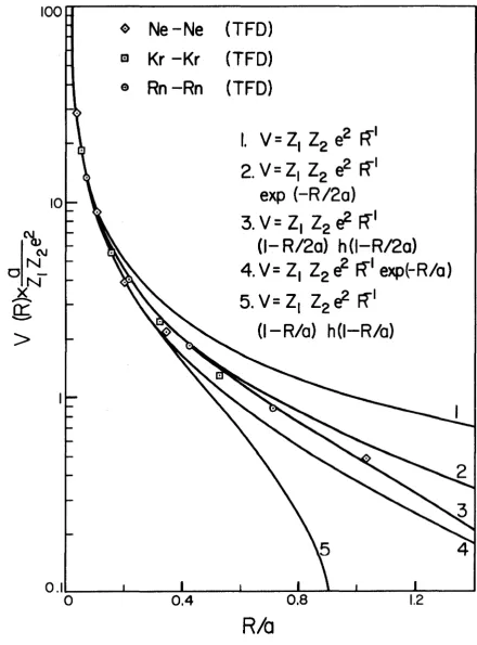
in te ra c tio n of noble-gas atoms, and has found good agreement w ith experiment a t small R. In Figure 1 Abrahamson's resu lts fo r Ne-Ne, K r-K r, and
Rn-Rn in tera c tio n s are shown, along w ith the a n a ly tic p o te n tia ls of Eqs. 1, 4 and 7, fo r both screening lengths a and 2a. Curve number 3 ,
representing the s h e ll-s h ie ld e d Coulomb p o te n tia l energy
»
Ne-Ne (TFD)
0
Kr - Kr (TFD)
®
Rn —Rn (TFD)
1. V=Z| Zge^ FT
2 .V = Z | Zg ( f FT
exp (-R /2 a )
3 . V = Z | Zge^R"'
(I- R/2o) h(l-R/2o)
4.V= Z|
T-
1
^
IT' exp(-R/a)
5 . V = Z , Zge^ R"'
(l-R /a) hd-R/o)
R/a
Figure I . Various p o te n tia ls as a function of in te rn u c le a r distance R. The points are Abrahamson's (1963) c a lc u la tio n s fo r in te ra c tio n s between
V ( R ) = (Z, Z ^ e ^ /R ) ( l - R / 2 a ) H ( l - R / 2 a ) ( 1 2 )
gives the best f i t fo r R ^ a , The corresponding cross section is given by Eqs. 8 and 9 w ith a replaced by 2a.
Cross sections fo r Bohr's screened p o te n tia l have been calcu lated num erically fo r several values of b/a (Everhart e t a l . 1955). For
7 T /2 ^ 0 < n and b /a ; ^ l, the Rutherford cross section is as much as a fa c to r of 2 .5 la rg e r than E v erh art's values, whereas the s h e ll-s h ie ld e d cross section (Eq. 8) always lie s w ith in 10% o f the numerical re s u lts .
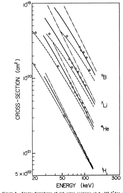
Our experimental s c a tte rin g cross sections ( t o be discussed
1 4 7 11
below) fo r H, He, Li and B on Au f o r a fix e d laboratory s c a tte rin g angle of 136.4° and a t laboratory energies from 50 to 110 keV are
presented as c ir c le s in F ig . 2. The Rutherford cross sections (dash-dot lin e s ) li e w ell above the s h e ll-s h ie ld e d (dashed lin e s ) and E v erh art's exponentially-screened Coulomb values ( O ' s ) . The good agreement between the s h e ll-s h ie ld e d and exponentially-screened Coulomb cross sections is evidence th a t backscattering is governed p rim a rily by the p o te n tia l a t distances R < a . This is so because the former in te ra c tio n is zero fo r R > a w hile the l a t t e r is no t. The s o lid curve, presenting the cross
sections of the s h e ll-s h ie ld e d Coulomb p o te n tia l w ith the screening radius doubled, agrees f a i r l y w ell w ith the reduced experimental data (Chapters V and V I) both in energy dependence and absolute valu e.
•>19
w w
OJi
Z O
LU C/)
s
o
(TU
\ \\\
20
50
100
ENERGY (keV)
300
CHAPTER 111 EXPERIMENTAL
Figure 3 is a schematic diagram of the apparatus. Honoenergetic ion beams a t energies below 120 keV are obtained from a magnetic
analyzer (van Wijngaarden e t a l . 1970). The angular divergence of the emerging beam is lim ite d to w ith in 0 .2 ° by a c ir c u la r s l i t system. A fte r c o llim a tio n the ion beam enters the ta rg e t chamber which is
- 7
maintained a t a pressure of the order of 10 T o rr. Regularly spaced th in ta rg e t film s of Au, vacuum deposited onto a th ic k Be p la te , can be moved across the path of the ion beam as indicated by the arrows. A Faraday cup connected to a bellows can be moved in to the path of the
ion beam. The absolute value o f the curren t is measured to w ith in
2% by a K eith le y 410 e le c tro m e te r. An Ortec Model E-013-025-100 surface -4
b a r r ie r d e te c to r, subtending a s o lid angle û, n = ( 5 .2 5 ± 0 .0 3 ) x 10
s r , is positioned a t 136.4° w ith respect to the incident ion beam. The pulses from the d etecto r are fed through a p re a m p lifie r (Ortec Model 109a), a main a m p lifie r (Ortec Model 4 8 5 ), a sin g le channel analyzer (Ortec Model 4o 6a), and are recorded by a d ig it a l ratem eter (Ortec Model 4 3 4 ).
3:1 Detector E ffic ie n c y
Any ion which is detected has passed through the Au electro de (228 % thickness) of the surface b a r r ie r d e te c to r, and then produced s u ffic ie n t io n iz a tio n to create a pulse d is c e rn ib le above the noise of the d e te c to r. To fin d the minimum energy fo r 100% d e te c tio n , the detector was placed d ir e c t ly in the path of monoenergetic *H + and ^He beams. With the lower d isc rim in ato r level of the single channel analyzer
10
11
0)
O'
k_
i
u_lO
OJ
(A 3 W
2
S.
a.
m j
I
cn
ID
1
u </>
2
12
fix e d ju s t above the detector noise le v e l, the detector e ffic ie n c y
(number of counts per incident p r o je c tile ) was observed to be e s s e n tia lly p e rfe ct fo r protons a t primary energies E % 40 keV and fo r ^He a t E ^ 50 keV. As the primary energy decreased below these values, so did the e ffic ie n c y of the d e te c to r. Below 10 keV no p a rtic le s could be detected.
I t is the counting e ffic ie n c y fo r the backscattered p ro je c tile s which is of in te re s t in the present experiment. The energy loss fo r these p ro je c tile s in the th in ta rg e t film s is q u ite small (Chapter V ), and 100% b a c k s c a tte re d -p ro je c tile counting e ffic ie n c y was expected fo r primary energies down to about the same lim it s . To v e r ify t h is , only incident energies were used fo r each p r o je c tile and each film fo r which the counting rate o f the backscattered ions in to the detector (8^ = 136.4°)
remained constant fo r a small range of the lower d isc rim in ato r s e ttin g s .
3 :2 FiIm Thickness
Five th in Au film s were vacuum deposited simultaneously onto Be and glass substrates using an Edwards Coating U n it (Model I2E A /722). The
thicknesses of the Au film s on the glass substrate were measured using o p tic a l techniques (Marton and Schleslnger 1969). To check th a t
corresponding Au film s on the two substrates were of equal thickness, the fo llo w in g experiment was performed. The glass-backed and Be-backed Au film s were successively irra d ia te d w ith ^He p ro je c tile s and the in te n s itie s of the backscattered p ro je c tile s from the various th in film s and the two substrates were measured. The backscatter y ie ld (number of backscatter counts per in cident p r o je c tile ) from the Be substrate was 0.2% of th a t from the thinnest Be-backed Au f ilm , w hile th a t of the glass was about 15% of the y ie ld from the thinnest glass-backed f ilm . A fte r
13 subtraction o f the substrate backscatter y ie ld s from those of the
th in film s , the re s u ltin g corrected y ie ld s were equal, w ith in experimental e rro r of about 2%, fo r corresponding film s on glass and Be, This agreement was found over the primary energy range 50-110 keV and fo r various film
thicknesses In the range 75-350 X. I t was, th e re fo re , concluded th a t ( I ) corresponding film s on glass and Be had the same thickness, and (2) the observed backscatter yie ld s could be corrected by subtraction of the
substrate y ie ld .
The measured thicknesses of the fiv e Au film s are 75, 120, 170,
CHAPTER IV RESULTS
4:1 Backscatter of
The fiv e Au film s and the Be substrate were bombarded in succession by proton beams of the order of lo ” *® A a t various fix e d primary energies
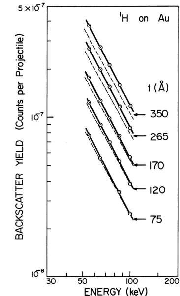
in the range 50-110 keV, The to ta l backscatter counts during 10 sec in te rv a ls were recorded fo r each film and the substrate a t each primary energy. Just p rio r to and immediately a f t e r each counting in te rv a l the incident ion curren t was measured to an accuracy of b e tte r than 2%. I f these two ion current measurements d iffe r e d by more than 5%, the data were discarded. In order to minimize s t a t i s t ic a l e rro rs a miniminn to ta l of 3000 backscatter events were recorded fo r each film a t each energy. The gross backscatter y ie ld , b' , was obtained by d iv id in g the backscatter counts per second by the p r o je c tile p a r tic le c u rre n t.
For a given film b" includes c o n trib u tio n s from both the Au film and the su b s tra te. At the highest primary energy the B' value of the substrate reached a maximum and equalled about 5% of the B^ value of
the thinnest Au f il m . The corrected backscatter y ie ld , 1^, was calcu lated (Sec 3*2) by subtracting the substrate y ie ld from each recorded film y ie ld . The energy dependence of the observed backscatter y ie ld , B^, fo r the
various Au film s is presented In F ig . 4 by the s o lid curves through
th e p o in ts m arked as c i r c l e s . The dashed c u r v e s , w h ic h r e p r e s e n t th e
same data corrected fo r energy loss in the film s and fo r m u ltip le sm all-angle s c a tte rin g e ff e c t s , w i ll be discussed in Chapter V I.
14
t (Â)
CL
350
265
170
Ü J
120
c/)
75
o
10
®30
50
100
ENERGY (keV)
200
16
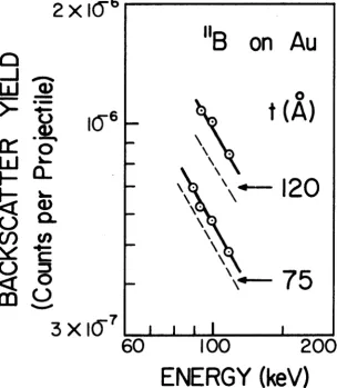
4 :2 Backscattering o f Ste. ^Li. and
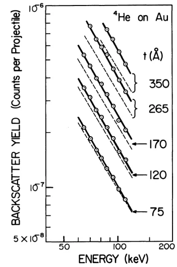
The fiv e Au film s and the Be substrate were a ls o irra d ia te d w ith monoenergetic beams of \ e ^ , ^ L i \ and ions. With these
p ro je c tile s the substrate y ie ld was e ith e r zero , or n e g lig ib le , being three orders o f magnitude sm aller than the thinnest film y ie ld in the
4
case of He. The observed values fo r the various th in film s are presented as c ir c le s In Figs. 5~7 as a function of primary energy. As the p r o je c tile mass increased, the primary energy fo r which 100% detection could be obtained increased ra p id ly , lim itin g the energy range of our
in v e s tig a tio n s .
17
6
He on Au
Q .
350
265
170
120
775
8
5 X
50
ICO
ENERGY (keV)
200
18
2 X 1 0
Q.
265
170
120
75
c/)
7
50
100
200
ENERGY (keV )
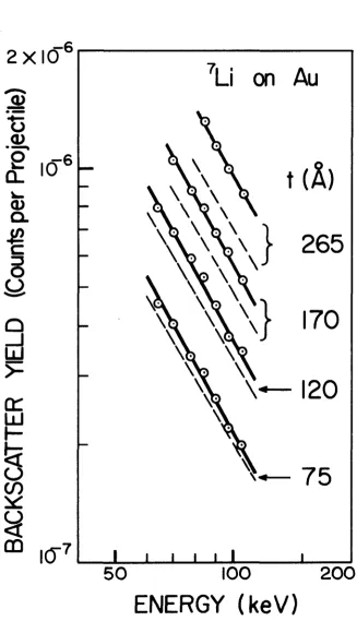
Figure 6 , The s o lid curves through the experimental points (c ir c le s ) show the dependence of the observed backscatter y ie ld on primary energy fo r ^Li impinging on various gold film s . The dashed curves, w ithout experimental p o in ts, are plots of the corresponding backscatter y ie ld s corrected fo r m u ltip le s c a tte rin g e ffe c ts versus the average energy.
19
2 X I ( T
on
Q _ j Ü J >
-120
75
3 X
60
100
200
ENERGY (keV)
CHAPTER V
ENERGY LOSS IN THE FILM
The observed Bq value consists o f p ro je c tile s backscattered anywhere Inside the film m a te ria l. Since the ion c o n tin u a lly loses energy as i t traverses the ta rg e t medium, there is a range of energies over which the main s c a tte rin g event can occur. In the absence of m u ltip le s c a tte rin g , the backscatter y ie ld is d ir e c t ly proportional to film thickness, and on the average a l l v io le n t c o llis io n s can be considered to occur a t the centre of the th in f ilm . To each Bq value we assign an average energy of in te ra c tio n E = E q -^ E , where Eq
Is the primary energy and aE is the energy loss in o n e-h alf of the film thickness. The /^E values have been computed using the energy-loss theory of Lindhard and S charff (1961) (Lindhard e t a l . I963) . We sh all now summarize some of the important aspects of th is theory.
The to ta l stopping power o f a ta rg e t m a terial fo r a p r o je c tile is re la te d to the to ta l stopping cross section S by
Æ = NS (13)
dR
where N is the atomic density o f the ta rg e t medium. Although an energetic atomic p r o je c tile is d e fle c te d only by nuclear c o llis io n s
(Bohr 1948), the energy of the p r o je c tile is dissipated to both electro ns
and r e c o i l i n g atom s In th e s to p p in g m edium . Thus th e t o t a l s to p p in g c ro s s
section consists o f the stopping cross section ^ fo r less in energy in nuclear c o llis io n s and the stopping cross s e c t Iw fo r loss In
energy to e le c tro n s :
20
21
S = S ,+ Sq . (14)
From Eqs. 13 and 14 we see th a t
dR IdRln WRie (15)
/dE\ =NSn and m =NS@. (16)
IdRln idRJe
To obtain a universal d e scrip tio n fo r energy loss, which is v a lid fo r a l l atomic p r o je c tile -ta r g e t combinations, Lindhard e t a l . introduced the dimensionless va riab le s
€ = E amg (1 7 )
Z|
and P = R Nrog4iTa^mi
(m, i- m^) (1 8 )
fo r energy and range re s p e c tiv e ly . In terms o f these v a riab le s Eqs. 16 can be w r itte n as
'dE) _ 4naZ, Zz«P (19)
dR/f, (m,+ m j n
and = 4naZ, Z g ^ . ^ . (20)
IdRL (m, + mz) \d ? /*
Lindhard e t a l . present a universal curve (F ig . 8) fo r / § £ \ versus ( d ? / n
6^ which is based on the Thoroas-Fermi s t a t i s t ic a l model of the c o llid in g atoms. In terms of the new v a riab le s the e le c tro n ic stopping power is given by
22 ro lO
Vü
$
(0 4J 0 ■21
§
u M-O o Ë 3 4-m <A m 0-•4/ •o o> c *cL a. o M <0 e1
002
I iZ23
where K = z}^^Q.0793 z t z f (A, + (22) ( z p T z p p - Â p ^
in which and Ag are the atomic numbers of the p r o je c tile and ta rg e t atoms re s p e c tiv e ly . The values of K fo r ^H, ^He, ^Li and on Au are
15.13, 3*00 , 1.71, and 1,216 re s p e c tiv e ly . Thus using F ig . 8 fo r /dg\ and Eqs. 21 and 22 fo r /d e l, one can compute the dE. values from
Id fin Id We dR
Eqs. 15, 19 and 20.
The energy loss aE In a th in stopping region of thickness <&R (much sm aller than the range of the p r o je c tile ) is then found from the r e la tio n ship
AE e /d & j AR (23)
where + (24)
and
The simple a n a ly tic form (Eq. 21) ap p lies only fo r p r o je c tile 2/3
24
energies of 120 keV, allow ing us to compute fo r protons as w ell as fo r heavier p ro je c tile s over the e n tir e energy range in ve s tig ate d .
2/3
For v e lo c itie s v> Vj= VqZj e le c tro n ic stopping completely dominates, but i t is no longer proportional to v . For v < V j e le c tro n ic stopping s t i l l dominates fo r Z^< Zg. For heavier p ro je c tile s and or
decreasing energy, nuclear stopping gradually overtakes e le c tro n ic stopping to become the major mechanism of energy loss. However even fo r our heaviest p r o je c tile ( * * B ) , a E^ remains a fa c to r of 4 la rg e r than A E ^. For th is reason the model described by McCracken and Freeman (1 9 69 ), where the
incident ion tra v e ls in s tra ig h t lines except fo r v io le n t c o llis io n s , should be co rrec t to a f i r s t approximation fo r lig h t ions.
The average aE values in the thinnest film are 0.7 keV fo r protons,
4 7 I I
/^ l keV fo r He and Li and ^ 1 . 8 keV fo r B. Even large u n c e rta in tie s in these small energy corrections s t i l l allows us to obtain the average energy of in te ra c tio n , E = E ( ,-aE, to a s u f f ic ie n tly high degree of
p recisio n .
CHAPTER VI
MULTIPLE SCATTERING EFFECTS
I f the in cident ions tra v e lle d s t r a ig h t - lin e paths in the ta rg e t m a terial u n til they suffered a sing le v io le n t in te ra c tio n and were
scattered , and then proceeded re c ti I in ea rl y out of the stopping medium, only p a rtic le s scattered in to A jn = 5 ,2 5 x l o ”^ s r about 8 ^ = 1 3 6 ,4 ° would reach the d e te c to r. As a consequence of m u ltip le sm all-angle scatterin g s before the v io le n t c o llis io n , the beam gradually spreads out about the d ire c tio n o f i n i t i a l incidence, in any in fin ite s im a l time in te rv a l
dT,
there is a p ro b a b ilitycr(e,E)dT
f o r each p a r tic le to bescattered back, where 6 is the s c a tte rin g angle w ith respect to the d ire c tio n of motion immediately preceding s c a tte rin g and E Is the p r o je c tile energy a t th a t in s ta n t. The p r o je c tile density in the diverging beam is azim uthally is o tro p ic . Because the Rutherford cross section is h igh ly preferred in the forward d ire c tio n , p a rtic le s
tr a v e llin g a t angles 0<0|_= 136.4° w ith respect to the d etecto r are more l i k e l y to e n te r the detector than those w ith 0 > 0 ^ . Con
sequently more p a rtic le s are m u ltip ly -s c a tte re d in to the s o lid angle of the detector than out of i t , re s u ltin g in an enhancement of the
backscatter y ie ld . Backscattered p a rtic le s a ls o s u ffe r small d e fle c tio n s , fu rth e r enhancing the backscatter y ie ld . To compare the observed
b a c k s c a t t e r y ie ld w ith the th e o r e tic a lly predicted one fo r a sing le s c a tte rin g e ven t, a c o rrectio n roust be applied to B^.
26
6:1 Angular Divergence
To fin d the co rrec tio n fa c to r by which the observed backscatter y ie ld must be divided in order to c o rrec t fo r m u ltip le sm all-angle d e fle c tio n s , an estim ate of the angular divergence of the beam in t r a v e llin g through a th in stopping region is required. Suppose the p r o je c tile encounters several s c a tte rin g centers on its passage through the stopping medium. Since the in d ivid u al d e fle c tio n s are completely random, the average d e fle c tio n is ze ro . The root-mean-square (rms) d e fle c tio n w i ll not vanish, however, since there e x is ts a random walk
in angle away from the d ire c tio n of i n i t i a l incidence. The to ta l rms d e fle c tio n associated w ith the p r o je c tile penetrating a depth aR in to the medium can be estim ated as fo llo w s* Consider an e la s t ic c o llis io n between two atoms in which the p a rtic le s are d eflected through the common angle of s c a tte rin g 6 in the CM system. From Appendix I I I the p r o je c tile
(m^) tran s fe rs an amount of energy to the re c o ilin g ta rg e t (m^) equal to
T = 4m,m2 E s i n 2 ( 8 / 2 ) , (27) (m |+ mg)^
where E is the impact energy. For lig h t p ro je c tile s (m j^«m ^), the lab and CM systems are almost id e n tic a l, and 6-6^^. Since the vast m a jo rity of c o llis io n s are sm all-angle ones Eq. 27 reduces to
T 2 4 (m ,/m 2 )E (8 /2 )2 . (28)
When a s w ift ion traverses a th in stopping region, i t undergoes several small d e fle c tio n s from it s o rig in a l d ire c tio n of motion, losing an amount of energy
27
*E n = = T, (29)
in atomic r e c o ils , where the summation includes a l l s c a tte rin g events. S u b stitu tin g fo r T; from Eq. 28, the nuclear energy loss becomes
2 2
AEn=i(m|/m2) L E ;8| ^(m |/m 2)E [ 6 ; (30)
where E; is the p r o je c tile energy p rio r to the i^^ c o llis io n . In a th in film the p r o je c tile energy remains n early constant and has, th e re fo re , been taken outside the summation sig n . I f a l l s c a tte rin g angles are sm all, the re s u ltin g angular d is tr ib u tio n is approximately gaussian
(Bohr, 1948) w ith a root-mean-square width
♦ m s - (3 1)
i yE m,
The c a lc u la tio n of a E^, has been described in the previous Chapter. Because a l l s c a tte rin g events are not small angle ones, the actual angular d is tr ib u tio n w i ll d i f f e r from a gaussian. Eq. 31 is , th e re fo re , considered to be only a rough estim ate of the angular divergence.
6 :2 Correction Factor
The c o rrec tio n fa c to r (CF = B<j/B) is the fa c to r by which the
o b s e rv e d b a c k s c a t t e r y i e l d , enhanced by th e e f f e c t s o f m u l t i p l e s m a
28
(1 ) The Rutherford cross section gives the form of the
backscattered angular d is tr ib u tio n . Since fo r large s c a tte rin g angles the shape of the angular d is tr ib u tio n is but l i t t l e a ffe c te d by e le c tro n ic screening, th is assumption introduces only small e rro rs .
(2 ) A ll backscatter events occur a t a film depth AR = t / 2 where t is the f ilm thickness.
(3 ) Just p rio r to backscattering the incident ions are d is trib u te d over an angular d is tr ib u tio n of gaussian form, centered about the incident d ire c tio n , whose rms width is given by Eq. 31 w ith 6 R = t / 2 .
(4) As the backscattered ions tra v e l out of the film they
again spread out in a gaussian angular d is tr ib u tio n about t h e ir o rig in a l s c a tte r d ire c tio n s , w ith an rms width a t the film surface again given by Eq. 31 but w ith ^ R = ( t / 2 ) / T , the average distance the ions tra v e l through the f ilm a f t e r being scattered from the film center towards the d e te c to r.
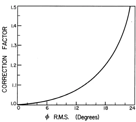
The results of the computation are presented in F ig . 9 as a p lo t of the c o rrectio n fa c to r versus $ , the predicted rms width of the
angular d is tr ib u tio n fo r AR = t / 2 . The co rrec tio n fa c to r was found to be s lig h t ly sm all, A b e tte r one was obtained by replacing $ , as
calcu lated from Eq* 31, w ith I . 10 ÿ and reading the co rrec tio n fa c to r from the same curve (F ig . 9 ) , The new values were found to be adequate (See Section 6 :3 ) fo r a l l film thicknesses and a l l p ro je c tile s a t a l l energies in ve s tig ate d .
The dependence o f B (the Bq value corrected fo r m u ltip le s c atte rin g e ffe c ts ) on the average energy of in te ra c tio n (the primary energy corrected fo r energy loss In the film ) is represented by the
29
cr
oo
<
o
o
ÜJ
cr
cr
o
o5
.4
3
$
2
0
6
12
18
<f>
R.M.S.
(Degrees)
24
3 0 dashed curves in Figs. 4 - 7 . Both axes in each of these diagrams have a dual meaning. The abscissa represents the primary energy Eq fo r the s o lid curves, and the average energy E = Eo- a£ fo r the dashed curves. The ordinate represents the observed backscatter y ie ld B© fo r the s o lid curves, and the corrected y ie ld B=Bo/CF fo r the dashed curves.
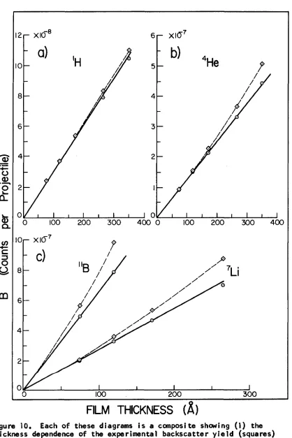
6:3 Dependence of Backscatter Y ie ld on FIIm Thickness
The dependence of the observed backscatter y ie ld Bo on the measured film thicknesses a t an average In te ra c tio n energy of 100 keV
is shown by the dashed curves through the experimental points marked as squares in F ig . 10. Since smooth curves can be f i t t e d qu ite n ic e ly through these p o ints, the film thickness measurements appear to be accurate w ell w ith in the u n certain ty of ± 5
In the absence of m u ltip le s c a tte rin g the backscatter y ie ld should be proportional to film thickness fo r t values much sm aller than the
range of the p r o je c tile in the f ilm . The c ir c le s in F ig . 10 represent the same data as the squares, but the ordinate now represents the y ie ld corrected fo r m u ltip le d e fle c tio n s (B = Bo/CF). S tra ig h t lin e s (the s o lid curves) passing through the o rig in provide good f i t s to the B values, in d ic a tin g th a t the co rrec tio n fa c to r fo r m u ltip le d e fle c tio n s may be f a i r l y accu rate. I t w i ll be noticed th a t m u ltip le s c a tte rin g e ffe c ts increase ra p id ly w ith increasing p r o je c tile mass. The reason fo r th is is th a t the r a tio AE„/m^ (See Eq. 31) increases w ith p r o je c tile mass.
The e r ro r in the c o rrec tio n fa c to rs is d i f f i c u l t to estim ate, but the deviations from u n ity of these fa cto rs appear to be accurate to , a t le a s t, w ith in 20%, For the thinnest film the average co rrectio n
31
_0> 0
<D 1
<D
a .
00
6 (— Xl(T XIO
5
4
3
2
_1 01^
4 0 0 0 4 0 0
100 200 3 0 0 100 200 3 0 0
- XIO
200 3 0 0
FILM THICKNESS (Â)
3 2 fa c to rs in the energy range in vestigated are 1 .0 2 , 1 .0 3 , 1.05 and 1.12 fo r **He, ^Li and re s p e c tiv e ly . A 20% e rro r in the deviations from u n ity of these numbers resu lts in a change in B of less than 1% fo r the three lig h te s t p ro je c tile s and less than 3% fo r the fo u rth . We conclude, th e re fo re , th a t the u n c e rta in tie s In B introduced by m u ltip le s c a tte rin g are p r a c tic a lly n e g lig ib le fo r the thinnest f ilm .
CHAPTER V il DISCUSSION
Because the data fo r the thinnest film are the most c e rta in , only the 75 % film re su lts w i ll be compared w ith theory. The laboratory backscatter cross section is given by (See Appendix IV)
i s : - _ B (32) dA N ( A /i) t
where a a is the s o lid angle subtended by the d etector and N is the
atomic density of the stopping medium. The cross sections fo r the various p ro je c tile s were c a lcu lated a t each energy in vestigated by s u b s titu tio n of nianerical values in to Eq. 32. The cross sections fo r near 100 keV were found to be 1.03 times the values predicted by the s h e ll-s h ie ld e d Coulomb p o te n tia l w ith a replaced by 2a (Eq. 1 2 ). Since the conversion from B value to cross section involves the measured value of the film thickness and its u n c e rta in ty , and the s t a t is t ic a l e rro r in B (le s s than 2%), no physical s ig n ifican ce can be a ttrib u te d to such a fa c to r . The observed cross sections fo r a l l p ro je c tile s have been divided by 1 .0 3 . This normalizes the th e o re tic a l and experimental values fo r a t 100 keV. The normalized cross sections are presented as c ir c le s in F ig . 2 . The
s o lid curves provide f a i r l y accurate f i t s to the data, both in magnitude and energy dependence. The s h e ll-s h ie ld e d Coulomb p o te n tia l, th e re fo re , q u ite accu rately describes the in te ra c tio n involved in backscattering of
lig h t atomic p ro je c tile s in the energy range in ve s tig ate d .
\ \ 0
m:
LU
33a
20
50
100
ENERG
Y (keV)
300
Figure 2, Energy dependence of lab cross sections a t 0l= 136.1+“ f o r various p r o je c tile s on g o ld, R utherford; ____ s h e ll-s h ie ld e d Coulomb a->2 a ; — - s h e ll-s h ie ld e d Coulomb; O screened Coulomb; o e xp erim en tal.
APPENDIX 1
THE SHELL SHIELDED COULOMB POTENTIAL Consider a p o te n tia l
:(0 /R ) (1 -R /a ) H (l-R /a ) (7)
where H(x) Is the Heavi side step fu n c tio n . Define U(R) = R (|>(R) = 0 ( l- R /a ) H ( l- R /a ) .
The charge d is tr ib u tio n g (R) giving ris e to th is p o te n tia l ^(R) is given by Polsson's equation
-4TTC(R).
For R > a , vanishes since iji does. For R < a , v^(jl= - 4ttQ. £(R)
For R = a , v^dl=ri d l LR ^>(«31 = 1 ^ U(R) R dR^ lR = a R dR^ R = a
Here 6 (R ) Is the Dirac d e lta fu n c tio n .
Therefore the to ta l v^^ (R ) =J. U"(a)-4TrQ. &XR) R
Note; U " (R )= 0 everywhere except a t R = a , To fin d U "(a), le t x = ( 1 -R /a ).
Then d f = 1 d l <jr2 dx^
and i d i U = l _ d iC x H C x )] R dR^ R a^ d x ^
=0. f z 6 ( x ) + X 5 * (x ) l since H '(x ) = <5(x). Ra^
35
2L & (x ) since f ( x ) & '( x ) = - 6 ( x ) f ' ( x ) Ra^
= & (1 -R /a ) Ra^
Q. 6^ (R-a) since S ( x ) = a ^ ( a x ) Ra
and 8 ( x ) = S ( -x )
0 &(R-a) since 8 ( x ) r O unless R = a. a£
Therefore V ^ t(R ) = & 8(R -a ) - I+ttO, <5(R) a&
= - 4 r r 6 ,
and the charge d is tr ib u tio n is
Ç r Q. &(R)-G(4Tra%) * 6 (R-a) ,
corresponding to a point charge Q. a t the centre of a spherical shell (radius a) of surface charge density -Q(4Tra^)
APPENDIX 11
THE CLASSICAL CROSS SECTION FOR THE SHELL-SHIELDED COULOMB POTENTIAL The v a lid it y of the c la s s ic a l c a lc u la tio n has been discussed by Bohr (1948) and by Mott and Massey (1 9 6 5 ). For a c la s s ic a l t r e a t ment to be v a lid , two conditions must be s a tis fie d :
(1 ) A « a , X « b where X is the de B roglie wavelength of the p r o je c t ile , b is the c o llis io n d ia m e te r,
and a is the screening length.
(2) e > X /2 T T a (See Bohr),
For the cases tre a te d In th is thesis ( H, He, L i, and B a t 50-110 keV on A u), the c la s s ic a l c a lc u la tio n is v a lid a t a l l s c a tte rin g angles 8 > 0 . 1 ° ,
The c la s s ic a l d if f e r e n t ia l s c a tte rin g cross sectio n .
= i d ( p 5 l., = i
d-n- 2 n s in 6 d0 d(cosO)
4 C lln! e /2 ) d(p%)
- 1
(33)
fo r a c en tral p o te n tia l, can be calcu lated from the re la tio n s h ip between the Center-of-Mass (CM) s c a tte rin g angle 6 and the impact parameter p. From the conservation of energy Goldstein (1959) finds
Xo
e=Tr-2 j d y / ^ l- V ( p /y ) /E - y 2 (34)
where y = p /R and y^ c p/R^. Here R^ is the turning point of the o r b it , determined by
E = L^/2uR2 + V (R J r Epf/R + V (R ,) (35)
37
where E is the CM energy, u is the reduced mass and L is the angular momentum.
o In terms of the new v a ria b le y and the parameter (l = Zj^Z2e ‘^ the
p o te n tia l (Eq, 7)
V (R )= d /R (1 -R /a ), O ^ R ^ a = 0 , R > a
becomes V ( p /y ) - Q y /p ( l - p / y a ) , y:^p /a = 0 , y < p/a
S u b stitu tio n of th is p o te n tia l in to Eq. 34 y ie ld s
p/a
8 = "rr-Z \ d y / \Jl-y^' -2 \ d y / \/ i -Qy( 1 -p /y a )/ (pE) -y ^ .
With w =Ea/Q., and c = p /a , we obtain
8 = TT-2 ^ d y / ^1-yZ -2 ^ d y / \ f l + ( l - y / c ) l / w -y ^
(7)
= TT-2 Arcsin y -2 Arcsin j^ (2 y + 1 /w c )/\/(w c )^ + 4 t 4 /w j ^
Using Eq. 35 , the upper lim it % becomes
2y„ = -l/w c + \ l i v i c y ^ + 4 + 4/w
On s u b s titu tio n of th is value in to the previous equation, we fin d
(1 + 2wc^)/ ^1 + (2w c)^(l 1/w^ 8 - 2 Arcsin
= 2 (A-B)
-2 Arcsin c
where sîn A = (I-(-2W c^)/ |/l + (2w c)^(l + 1/w)
3 8
cos A = 2wc / \/r+ (2wc)^ (1 + 1/w)
sin B = c
cos B = ^T-c^
From the previous equations i t follow s th a t
sin 0 /2 = sin(A-B) = sin A cos B - cos A s in B
and
1-c
1 + (2 w c )^ (l+ 1/w)
d (s in ^ J /2 )-
I d (s in ^ e /2 )
d(p^) afd(c%)I + 2w
-,
2
1 + (2wc)^ (1 + 1/w)(36)
= 1 [ i + j k a f l- c 2
s in ( 8 / 2 ) .
The la s t step Is e a s ily v e r if ie d by s u b s titu tin g fo r sin (8 /2 ) (Eq, 36), Thus the d if f e r e n t ia l s c a tte rin g cross section (Eq. 33) becomes
2 i+. l- c '
1 2w
CSC ( 8 / 2 ) , (37)
r (b /4 ) CSC (8 /2 ) = |a _ j^ e s c l 0 / 2 )
(fe)
which allows us to rew rite Eq. 37 In the form
dii-1-c^ 1 +2w
(fi).
w^ l à j \
d W
.1/2
where k = 2 w ( l- c ^ ) /( l+ 2 w )
With the a id of Eq. 36 , the k value becomes
k - l + b / ( 2 a )
1 + b/a + b V (4 a ^ s in 8 /2 )
and the d if f e r e n t ia l cross section is
d ^ =
dcL
ab (a + b /2)
4a sIn^e/2) (a + b) + b^ z
(38)
(9 )
(
8
)
39
APPENDIX 111
TRANSFORMATION FORMULAE BETWEEN LAB AND CM FRAMES
Because the e x p e rim e n ta lis t takes measurements in the laboratory (la b ) system, and the th e o re tic ia n finds i t sim pler to make his c a lc u la tio n s in the Center-of-Mass (CM) system, conversion formulae from one frame of reference to the other are necessary.
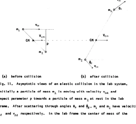
Consider a n o n r e la tiv is tic binary e la s t ic c o llis io n which asym pto tically appears in the lab system as in F ig . 11.
’'08
cm
CM
'e m
— >
(a ) before c o llis io n (b) a f t e r c o llis io n F ig . 11. Asymptotic views of an e la s t ic c o llis io n in the lab system.
I n i t i a l l y a p a r t i c l e o f mass is m oving w i t h v e l o c i t y v^^^ and
impact parameter p towards a p a r tic le of mass m ^ a t rest in the lab
frame. A fte r s c a tte rin g through angles dj^ and (|l^, m^ and ra^ have v e lo c itie s v,g and re s p e c tiv e ly . In the lab frame the center of mass of the
41
two p a rtic le s moves w ith constant v e lo c ity « The magnitude and d ire c tio n of are determined by the conservation theorem fo r to ta l lin e a r
momentum
(m^+ = m, Vo4
The CM system moves w ith respect to the lab system so th a t the o rig in of the CM system is always coincident w ith the center of mass of the c o llid in g p a r tic le s . In the CM frame the to ta l energy is
E = Ejj - i ( m i f mg^)vjn = ""z Eg #1+ m%
Because the to ta l lin e a r momentum is zero a t a l l times in th is frame, the p a rtic le s are tr a v e llin g in opposite d ire c tio n s to one another before and a f t e r the c o llis io n . Hence they share a common angle of s c a tte rin g , e (F ig . 12).
m 'e m
'em
m
'em
/(CM
(a ) before col 1 i s i on (b) a f t e r col 1is i on F ig , 12. Asymptotic views of an e la s t ic c o llis io n in the CM system.
42
From a vector ad d itio n diagram re la tin g the f in a l v e lo c itie s in the CM and lab frames, the re la tio n s h ip between the CM and lab s c a tte rin g angles can be obtained.
Vcm
'cm
'12
F ig . 13. A vector a d d itio n diagram of the v e lo c itie s of the p a rtic le s in the CM and lab frames.
tan = (%i *Vg.m) s in 6 _ s in 6
0
m^^/m^+cos e
The second step follow s by the d e fin itio n of the center of mass v e lo c ity : "’zycm" N ote t h a t i f 6 — 6^ and th e la b and CM
systems are almost id e n tic a l. For the case 6jj = 0|_= 1 3 6.4 °, the CM
43
Also from F ig , 13 we see th a t
2 sin (T T /2 -(|)^ )
and 2 t t- 0 .
Hence 2 s in (6 /2 )
and the k in e tic energy tra n s fe rre d to the ta rg e t I f the incident p r o je c tile is e la s t ic a lly scattered through 6 is
T«= = 4m, E s in ^ (e /2 ). (27) (m, + m^)
111:1 R elationship of the Cross Sections
In an actual experiment the counting rate of a fix e d d etecto r is independent of the reference frame of the observer,
i . e . I i ^ \ dxL - / ^ \ dr^e \d W Vdnjji
For s c a tte rin g by s p h e ric a lly symmetric p o te n tia ls , the s c a tte rin g d is tr ib u tio n is independent of the azimuthal ang le, so th a t
drig_ sin 6g dQa . dj^ “ s i n e de
S u b s t i t u t i n g In 0^ = 0|_= 1 3 6 .4 and th e CM s c a t t e r i n g a n g le s d e te r m in e d
above, the ra tio s (d-ajj/dn _) fo r ^H, ^He, ^Li and on Au are found to be 1.0074, 1.0302, 1.0538 and 1.0956 re s p e c tiv e ly . The cross sections c a lcu lated in the CM system are converted to the lab system by d iv id in g by these fa c to rs .
APPENDIX IV
EXPERIMENTAL DIFFERENTIAL SCATTERING CROSS SECTION
Consider a th in ta rg e t f i l m of thickness t and density N atoms per u n it volume. In a th in f i l m no ta rg e t atom is blocked by any o th e r. Suppose a co llim ated beam of monoenergetic p ro je c tile s and cross-sectional area A s trik e s the f i l m a t normal incidence. The nimiber of s c a tte rin g centers in the path of the beam Is given by the product AtN. Denoting the d if f e r e n t ia l cross section per ta rg e t atom fo r s c a tte rin g in to a u n it s o lid angle in the d ire c tio n 8^ in the laboratory system by d q ~( 6 f . Ef ) . the e ffe c tiv e ta rg e t area presented to the beam fo r such
d ^
s c a tte rin g is
AtN û £ i § j L J k ) d s i .
where E_g is the lab energy. The fra c tio n of the in cident p a rtic le s backscattered in to the u n it s o lid angle is
Nt d q - ( 6 i.E j) d XL
I f a detecto r subtends a lab s o lid angle AXi_, and the fra c tio n of the incident ions detected is denoted by B (the backscatter y ie l d ) , then
B ^ N t dcr(6fl . E a ) A x l . d XL
The lab d if f e r e n t ia l s c a tte rin g cross section is then
. (32)
d N (A ix jt
BIBLIOGRAPHY
A braham son, A . A . 1 9 6 3 . P h y s . R e v . 1 3 0 , 6 9 3 .
B e h r ls c h , R . 1 9 6 8 , C a n , J , P h y s , 5 2 7 ,
B e h r is c h , R , 1 9 6 9 , P h y s , L e t t e r s , 3 0 A , 5 0 6 ,
B e r g s tr o m , I , and D o m e ij, B , 1 9 6 6 . N u c l, I n s t r . M ethods 1 4 6 ,
B o h r , N , 1 9 4 8 . k g l , Danske V id e n s k a b , S e ls k a b , M a t , F y s , M edd, N o , 8 ,
E v e r h a r t , E , , S to n e , G, and C a rb o n e , R . J . 1 9 5 5 . P h y s , R e v , _99, 1 2 8 7 ,
F l r s o v , 0 , B , ( 1 9 5 8 ) . S o v ie t P h y s . -JE TP 7 , 3 0 8 ,
G o l d s t e i n , H , C l a s s i c a l M e c h a n ic s ( A d d is o n -W e s le y P u b l, C o ,, I n c , , R e a d in g , M a s s , 1 9 5 9 ) , C h a p te r 3 ,
L in d h a r d , J , and S c h a r f f , M , 1 9 6 1 , P h y s . R e v . 1 2 4 , 1 2 8 .
L in d h a r d , J , , N i e l s e n , V , , S c h a r f f , M , and Thom sen, P , V , 1 9 6 3 , k g l , D anske V id e n s k a b . S e ls k a b . M a t . F y s . M edd, 3 ^ , N o, 1 0 , M a r t o n , J , P , and S c h le s in g e r , M , 1 9 6 9 , J , A p p l, P h y s , 4 0 , 4 5 2 9 .
M a y e r , J , W ,, E r ik s s o n , L . , P i c r a u x , S , I . and D a v ie s , J , A , 1 9 6 8 , C a n . J , P h y s , 6 6 3 ,
M c C ra c k e n , G , M , and F reem an , N , J , 1 9 6 9 , P r o c , P h y s , S o c , B , 2 , 6 6 1 , M o t t , N , F , and M a s s e y , H , S , W, T h e o ry o f A to m ic C o l l i s i o n s (O x fo r d
U n i v e r s i t y P r e s s , L o n d o n , 1 9 6 5 ) , p , 1 1 0 ,
S igm und, P , 1 9 6 8 , C a n , J , P h y s . 7 3 1 .
S igm und, P , 1 9 6 9 , P h y s , R e v , 1 8 4 , 3 8 3 ,
S m ith , F , T , , M a r c h i, R . P , , A b e r t h , W ,, L o r e n t s , D , C , , and H e in z , 0 , 1 9 6 7 , P h y s , R e v , 1 6 1 . 3 1 ,
v a n W ljn g a a r d e n , A , , M ir e m a d i, B , , B r im n e r , E , J , and B r a d f o r d , J , N . 1 9 7 0 , C an , J , P h y s , (May I s s u e ) ,
W h a lin g , W, 1 9 5 8 , HanJbuch d e r P h y s ik ( S p r i n g e r - V e r l a g , B e r l i n ) , V o l . 3 4 , p . 1 9 2 ,
45
V IT A AUCTORIS
Born November 6 , 1946 in Leamington, Ontario.
Received elementary and secondary school education at Harrow, Ontario.
Graduated from University of Windsor with B. Sc. in Physics in 1 9 6 9 .