IEEE 754 Single Precision Floating Point
Arithmetic Unit Using VHDL
Adil Shaikh1, Akash Ninave2, Nihal Nitnaware3, Prof. Shaiwali Ballal4
U.G. Student, Department of Electronics Engineering, Vishwakarma Institute of Technology Pune, Maharashtra, India1 U.G. Student, Department of Electronics Engineering, Vishwakarma Institute of Technology Pune, Maharashtra, India2 U.G. Student, Department of Electronics Engineering, Vishwakarma Institute of Technology Pune, Maharashtra, India3
Professor, Department of Electronics Engineering, Vishwakarma Institute of Technology Pune, Maharashtra, India 4
ABSTRACT:Almost all of the algorithms implemented in FPGAs used in fixed-point. Floating-point operations are useful for computations involving large dynamic range, but they require more resources than normal integer operations. With the current system requirements and available FPGAs, floating-point implementations are becoming more common and designers are taking advantage of FPGAs as a platform for floating-point implementations. As compared to application specific integrated circuit, field programmable logic array (FPGA) provide reduced development cost and time and rapid advancement in technology make it suitable to implement floating point arithmetic unit. Additionally, its flexibility enables field upgrade and adaptation of hardware all in run time condition. A 32 bit floating point arithmetic unit with IEEE 754 Standard has been designed using VHDL code and all operations of addition, subtraction, multiplication and division are tested on Xilinx.
KEYWORDS: Floating Point, Arithmetic Unit, VHDL, Xilinx, FPGA.
I.INTRODUCTION
The IEEE-754 floating point operations have found in computer in number of various applications in the various engineering fields for the requirements of high speed delicate operation due to its easy operation rules, large range and high precision. It is focused on designing VHDL codes to develop processing unit. Due to increase in high speed scientific operations and increased signal processing requirement the high speed floating point unit is playing the important role in these area. The implementation of the floating point arithmetic has been quite easy and convenient in the floating point high level languages, but the implementation of the arithmetic by hardware is very difficult. Due to development of semiconductor and very large scale integration (VLSI) technology, Field Programmable Gate Arrays (FPGAs) are the best options for implementing floating point hardware arithmetic units due of their high density, cost effectiveness, better performance and flexible operations requirements for high speed precious operation.
In this paper, IEEE754-single precision (32-bit) high speed floating point arithmetic unit is designed using VHDL code. Flowcharts and algorithms have been presented and all operations of addition, subtraction, multiplication and division are tested on Xilinx and verified successfully. Thereafter, the new feature of creating test-bench for verification of VHDL code of that 32-bit Floating Point Arithmetic Unit in Xilinx simulator has been explained. The simulation results of addition, subtraction, multiplication and division are demonstrated
II. RELATED WORK
runtime condition property [2]. The long series of work on floating point unit in FPGA have been have been investigated [1, 2, 3, 4,]. The FPGA is uncompetitive with CPU in terms of Flops but they provide sustained performance for floating point unit.
III. FLOATING POINT ARCHITECTURE
The real numbers are represented in binary format in different ways the floating point number is use for the same; the IEEE 754 [1] standard has presented two different floating point formats, Binary interchange as well as Decimal interchange format. The paper is focusing only on IEEE-754 single precision normalized binary format. Figure1 shows The IEEE-754 single precision binary format. It consists of a 1 bit sign (S), 8 bits exponent (expo), and a 23 bits fraction part M) or Mantissa.
32 bit Single Precision Floating Point Numbers IEEE standard are stored in following:
S EEEEEEEE MMMMMMMMMMMMMMMMMMMMMM
S: Sign – 1 bit E: Exponent – 8 bits
M: Mantissa – 23 bits Fraction
Figure1. IEEE 754 single precision format
Let ‘V’ be a number, ‘F’ is the fractional part of mantissa and ‘expo’ be the exponent part of floating point number. The value of number V:
If expo=255 & F is nonzero, then V is Not A Number (NAN) If expo=255 & F is zero and S is 1, then V is Infinity
If expo=255 & F is zero and S is 0, then V is Infinity
If 0<expo<255 then out1= (-1) **S * * (1.F)* 2 ** (expo-127) (exponent range = -127 to +128) If expo=0 and F is nonzero, then V= (-1) **S * (0.F) * 2 ** (-126) ("un-normalized" values”) If expo=0 and F is zero and S is 1, then V= - 0
If expo=0 and F is zero and S is 0, then V = 0
An extra bit is added to the mantissa to form a significand. If the exponent is greater than 0and smaller than 255, and there is 1 in the MSB of the significand then the number is said to be a normalized number; in this case the real number is represented by (1)
V = (-1s) * 2 (expo - Bias) * (1.M) …..(1)
Where M = m22 2-1 + m21 2-2 + m20 2-3+…+ m1 2-22+m0 2-23; Bias = 127.
IV.ALGORITHMSFORFLOATINGPOINTARITHMATICUNIT
1)Floating Point Addition / Subtraction
The flowchart explains the algorithm for addition and subtraction. Depending on the sign of these numbers two cases arises. Case I: when both the numbers are of same sign i.e. either positive or negative. In this case Most Significant Bit of both the numbers are either 1 or 0. Case II: when both number having same sign it means MSB of number in1 and in2 are different which shows number is negative.
Case I: - When both numbers are of same sign
Steps:-
1:- Enter the two numbers in1 and in2 each of 32 bits. expo1, S1 and expo2, S2 indicates exponent and significand of in1 and in2 respectively.
2:- Check if expo1 or expo2 is zero, if it is zero then set hidden bit of respective input number ‘0’, if expo1 and expo2 is not ‘0’ check if expo2>expo1 swap in1 and in2 else keep them as it is.
3:- Now calculate the difference between expo1 and expo2.let’s say this difference is d, d= expo1-expo2. If difference ‘d’ is zero then there is no change else left shift significand of in2 which is S2 by the amount ‘d’ along with the hidden bit which us ‘1’
4:- Normalize the exponent of in2 by adding the amount d, expo2=expo2 (previous value) + d. now it is normalize because expo2 and expo1 are equal.
5:- Check if in1 and in2 have same sign by checking 32th bit of in1 and in2 which is sign bit. 6:- In this step add 24 bit significand (1 hidden bit and 23 mantissa) S1 and S2, i.e. S=S1+S2.
7:- Check for the carry whether carry is generated by significand addition, if it is generated then add ‘1’ in either expo1 or updated value of expo2. After that shift right addition of significand ‘S’ by 1 bit drop the LSB and make new MSB ‘1’.
8:- If no carry is generated in addition then skip step 7 and previous exponent is final exponent. 9:- The sign of result is either of in1 or in2 as it is of same sign.
10:- pack the result in 32 bit format as follow: =sing_f(1)exponent(8)S(23).
Case II: - When both numbers are of different sign Steps
1:- Enter the two numbers in1 and in2 each of 32 bits. expo1, S1 and expo2, S2 indicates exponent and significand of in1 and in2 respectively.
2:- Check if expo1 or expo2 is zero, if it is zero then set hidden bit of respective input number ‘0’, if expo1 and expo2 is not ‘0’ check if expo2>expo1 swap in1 and in2 else keep them as it is.
3:- Now calculate the difference between expo1 and expo2. Let’s say this difference is d, d= expo1-expo2. If difference ‘d’ is zero then there is no change else left shift significand of in2 which is S2 by the amount ‘d’ along with the hidden bit which us ‘1’.
4:- Normalize the exponent of in2 by adding the amount d, expo2=expo2 (previous value) + d. now it is normalize because expo2 and expo1 are equal.
5:- Check if in2 and in1 have different sign, if „Yes‟;
6:- Add 2’s compliment of S2 i.e. not (S2) +’1’ with significand of in1 ‘S1’.
7:-If carry is generated by addition of significand then discard carry and left shift the result till there is ‘1’ in MSB and count the number of shifting denoted by ‘z’.
8:- Final exponent is calculated by subtracting ‘z’ from either expo1 or expo2 (expo_f = expo1-‘z’) and append ‘z’ number of 0s in LSB part of significand.
9:- If there is no carry generated in step number 6 convert s‘ into 2’s compliment form and in this case MSB should be ‘1’;.
10:- Sign of the result i.e. MSB = Sign of the larger number either MSB of N1or it can be MSB of N2.
To implement this algorithm it requires one 24 bit full adder, two 8 bit adders, one swap unit, two shifter, and two subtractor in a design.
The two exponents are compared by first comparator, there is no need of shifting when exponent of two numbers are equal. Exponents are compared with zero by using second comparator. If exponent of any number i.e. either expo2 or expo2 is zero hidden bit is set to zero. Whether the expo2 is greater than expo1 is checked by third comparator and the numbers are swapped.
The difference between the exponents are calculated by first subtractor. When the numbers are having different sign and carry is generated by the significand addition of these numbers this carry is subtracted from the exponent using second 8 bit subtractor.
24 bit adder is required to add significands , first 8 bit adder is used when two numbers are having same sign and carry is generated from significand addition then this carry is added to the exponent. Second 8 bit adder is used to add shifted amount to the smaller exponent to make exponents normalized.
Two shift units are required to shift significand result right and left. Swapping unit is required to swap in2 with in1 if in2>in1 the result is saved into the third variable.
2) Floating point Multiplication.
The figure 3 shows the flowchart of multiplication algorithm of multiplication is demonstrated by flowchart. In1 and in2 are two numbers sign1, expo1, S1 and sign2, expo2, S2 are sign bit, exponent and significand of in1 and in2 respectively.
Steps for multiplication are as follows.
1:- calculate sign bit. sign_f= sign1 XOR sign2, sign_f is sign of final result.
2:- add the exponents and subtract 127 to make adjustment in exponent (expo1+127+expo2+127)-127. 3:- Multiply the significand. S=S1*S2.
4:- check for overflow and underflow and special flag. When the value of biased exponent is less than 1 it shows occurrence of underflow, if exponent is greater than 254 then it shows overflow of floating point operation.
5:- Take the first 23 bits of ‘S’ and from left side and discard remaining bits.
6:- Arrange the results in 32 bit format. 1 sign bit followed by eight bits exponent followed by 23 bits mantissa/significand.
Calculation of sign bit:- when both number have same sign the sign of result is positive else sign will be negative the sign in calculated by XORing both sign bits of inputs.
The multiplication result is 48 bits. If 47th bit is ‘1’ then right shift the result and add ‘1’ in exponent to normalize the product. 46th to 23th bits are actual significand product.
Exponent addition is done by unsigned 8 bit adder and to bias properly subtract 127 from the addition result for that purpose unsigned 8 bit subtractor is used. In any of the cases either addition of exponent in the beginning or while adjusting result the exponent must in the range 1 to 254. When overflow occur the result of multiplication goes to ±Infinity (+ or – sign is determined by the sign of two input numbers). When underflow occur it makes underflow flag high and the result goes to ±0 (+ or – signed is determined by the sign of two input numbers).
3) Floating point division.
The figure 4 shows the flowchart of division, algorithm for division is explained through this flowchart. In1 and in2 are two numbers sign1, expo1, S1 and sign2, expo2, S2 are sign bit, exponent and significand of in1 and in2 respectively. It is assumed that in1 andin2 are in normalized form.
Steps for floating point division is as follows.
1:- calculate sign bit. sign_f= sign1 XOR sign2, sign_f is sign of final result. 2:- divide the significand S1 by S2 for division binary division method is used. • Expand divisor and dividend to double of their size
- Expanded dividend = zeroes (24 bits MSB) dividend (32 bits, LSB)
• For each step, determine if divisor is smaller than dividend - Subtract divisor from dividend look at sign
- If result is greater than or equal to ‘0’: dividend/divisor>=1, mark quotient as “1”.
- If result is negative: divisor larger than dividend; make in quotient as “0” • Shift quotient left and divisor right to cover next power of two.
3:- Subtract the expo2 from expo1. 4:- check for overflow and underflow flags. 5: assemble the result in 32 bits format.
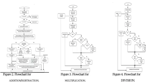
V.FLOWCHART FOR ALGORITHM.
Figure 2. Flowchart for Figure 3. Flowchart for Figure 4. Flowchart for
ADDITION/SUBTRACTION. MULTIPLICATION. DIVISION.
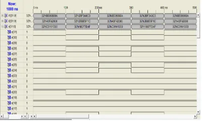
VI.VERIFICATIONOFRESULT
VII. EXPERIMENTAL RESULTS
Results and analysis Design Summery Entity diagram
Figure 5. Design summary Figure 6.Entity diagram of floating point unit Sel signal is used to select any of the four operation addition, subtraction multiplication and division. In1 an d in2 are 32 bit input numbers, out1 is 32 bit output and clk signal is used to provide clock signal to the design.
Addition/subtraction: Multiplication:
Division:RESULT TABLE
Figure 9. Simulation of division. Table 1. Result
VIII. CONCLUSION
The VHDL code written for complete 32-bit floating point arithmetic unit is implemented and tested on Xilinx. A process described to create Test-bench for verification of VHDL code in Xilinx Simulator is used on the same VHDL code and results were found in order. VHDL code can be regenerated with the optimized results and tested on Xilinx to see the improvement in the parameters. In future the “herbie’s algorithm’ can be implemented to reduce to errors in floating point operations by 40%.
REFERENCES
[1] David Goldberg, “what every computer scientist should know about floating point arithmetic”, ACM Computing Surveys (CSUR) Volume 23 Issue 1, March 1991.
[2] Keith Underwood, “FPGAs vs CPUs: TRENDS IN PEAK FLOATING POINT PERFORMANCE”, FPGA '04 Proceedings of the 2004 ACM/SIGDA 12th international symposium on Field programmable gate arrays. Monterey, California, USA — February 22 - 24, 2004.
[3] Per Karlstrom, Andreas Ehliar, Dake Liu, “High Performance, Low Latency FPGA based Floating Point Adder and Multiplier Units in a Virtex 4,” IEEE Conference, Linkoping, Sweden, 20-21 Nov 2006.
[4] Ping-Tak Peter Tang, “Table-driven implementation of the exponential function in IEEE floating-point arithmetic,” ACM Transactions on Mathematical Software (TOMS) volume 15,New York, NY, USA issue 2 june 2002.
[5] M.F. Cowlishaw , E.M. Schwarz, R.M. Smith ,C.F. Webb, “A decimal floating-point specification,” in computer Arithmetic, 2001. Proceedings. 15th IEEE Symposium on, Vail, CO, USA, USA, 11-13 june 2001.
[6] Nicholas J. Higham,”The Accuracy of Floating Point Summation,”Society for Industrial and Applied Mathematics, 13 July 2006.
[7] Michael J. Beauchamp, Scott Hauck, Keith D. Underwood, K. Scott Hemmert, “Embedded floatingpoint units in FPGAs,” Proceedings of the 2006 ACM/SIGDA 14th international symposium on Field programmable gate arrays, Monterey, California, USA - February 22 - 24, 2006. [8] Vikas Gupta, Anshuj Jain, Bharti Chourasia,” FPGA Based Implementation of Genetic Algorithm Using VHDL,” International Journal of Electronics Communication and Computer Technology (IJECCT) Volume 1 Issue 1 | September 2011.