Numerical Investigation on the Flexural
Behaviour of RC Beams using Microplane
Model
Merlin Mary Vilson 1, Airin M.G 2
P.G. Student, Department of Civil Engineering, SSET, Karukutty, Kerala, India1
Associate Professor, Department of Civil Engineering, SSET, Karukutty, Kerala, India1
ABSTRACT: The response of a reinforced concrete structure is determined by the material response of the plain concrete and steel of which it is composed. Thus, analysis and prediction of structural response to static or dynamic loading requires prediction of concrete response to variable load histories. Continuum mechanics provides a framework for developing a numerical model that describes these fundamental characteristics. Microplane model is a constitutive material model developed by P. Bazant et al., in 1980. This is a microstructural model in which the material properties, such as the material stiffness matrix, are integrated from elemental behaviour of microplanes. It is the most general model developed so far for use in the finite element analysis. In this, the stress strain relationship of a material can be defined in an independent manner on planes of various orientations called microplanes, by assuming either a static constraint or a kinematic constraint. Here, the microplane model has been used in an RC beam for analysis. And it showed that microplane model is giving comparable results with that of experiment and better results than that of finite element software.
KEYWORDS:Continuum mechanics, Microplane model, Static constraint, Kinematic constraint.
I. INTRODUCTION
In this age of technology, studies on materials are being done at micro as well as nano levels. Concrete has been regarded as a low tech and well understood material. However, concrete being the second most consumed material in the world, an impressive amount of research has been carried out over the last century and the studies are being pursued, in order to understand the phenomenon and mechanisms that are governing its complex behaviour. The complex macroscopic behaviour and failure mechanisms of concrete can be determined by observing the heterogeneous structure at nano, micro and meso levels. And in fact, still today, there is plenty of scope for exploring the fundamental nature of concrete and its behaviour. Nowadays, for detailed studies of materials, we usually go for mathematical models. Mathematical models currently available for concrete are, as yet incapable of reproducing the mechanical behaviour as well as transient behaviour of this material in a very accurate manner. Even though different mathematical models are available, long-standing issues regarding concrete complexities remain to this day. One such aspect is modelling the mechanical behaviour of concrete. The lack of a widely accepted and accurate mathematical model for predicting the mechanical behaviour of concrete in practice prevents the widespread use of non linear analysis of concrete structures. This may also pose a hindrance to the development of the new research areas on concrete.
Paper is organized as follows. Microplane model in general is discussed in Section II. Section III describes the numerical analysis of a simply supported RC beam using microplane model. Section IV presents analytical results with discussions. Finally, Section V presents conclusion.
II. MICROPLANEMODELLING
The microplane model was developed by Bazant et al., in 1980. The first generalized microplane model employed an idea, initially proposed by Taylor (1938) and subsequently applied by Batdorf and Budianski (1949) in a constitutive model for polycrystalline metals. According to Taylor (1938) the stress strain relationship of a material can be defined in an independent manner on planes of various orientations called microplanes, by assuming either a static constraint (i.e. the stresses on a microplane are the resolved components of the macroscopic stress) or a kinematic constraint (i.e. the strains on a microplane are the resolved components of the microscopic strain tensor). The kinematic constraint was adopted by Bazant and Prat (1988) since it enabled a stable response during strain softening.
(a)
Fig.1 (a) Microplane theory (Michael et al., 2006)
The essential feature of this material formulation is a split of the local microplane strains and stresses allowing one to resort to simplified or in certain cases even unidirectional constitutive laws. The main attraction of the microplane concept is that an initial or evolving anisotropic material behaviour can be described in a natural and simple way. Motivated from a macroscopic viewpoint, it is advocated to restrict the microplane concept to the pure volumetric-deviatoric split, as a constraint subset of the most often applied volumetric-volumetric-deviatoric-tangential split. This variant has the particular advantage that typical macroscopic responses are directly reflected on the mesoscale.
The microplane theory is shortly summarized in a schematic form in Fig.1. The three main steps of the microplane model are illustrated. The first step is the projection part. Here a kinematic constraint is applied in order to relate the macroscopic strain tensor to their microplane counterparts. The kinematic constraint assumes that the microplane strains are equivalent to the projected macroscopic strain tensor, opposite to a static constraint, where the stresses are projected. The microplane strains can be derived as projections of the overall strain tensor ε, which corresponds to the symmetric part of the displacement gradient in the geometrically linear case. The second step describes the definition of constitutive laws on the microplane level. These constitutive equations are formulated between single stress and strain components on individual microplanes.
point level to derive the overall response. This homogenization process is based on the principle of energy equivalence.
Microplane theory is summarized in three primary steps.
1. Apply a kinematic constraint to relate the macroscopic strain tensors to their microplane counterparts. 2. Define the constitutive laws on the microplane levels, where unidirectional constitutive equations (such as
stress and strain components) are applied on each microplane
3. Relate the homogenization process on the material point level to derive the overall material response.
III.NUMERICAL ANALYSIS OF A SIMPLY SUPPORTED RC BEAM USING MICROPLANE MODEL
An RC beam as per “Effect of manufactured sand as fine aggregate on the strength, durability and structural properties of concrete” by P.M Shanmughavadivu, 2013 has been modelled and microplane model has been used in it. Fig.2 shows the loading diagram and meshed reinforcement model of the beam.
(a) (b)
Fig.2 (a) Loading diagram with support conditions (b) Meshed reinforcement model of the beam
Using this reference beam, a number of models have been made and analysis has been carried out in ANSYS Mechanical APDL 15 for different combinations of material models like:
1) CLSL - Concrete (Linear) & Steel (Linear)
2) CMLSL - Concrete (Linear, multi linear) & Steel (Linear) 3) CMLSBL - Concrete (Linear, multi linear) & Steel (linear, bilinear)
4) CMPSBL - Concrete (microplane)
5) CMLSMP - Steel (microplane)
6) CMPSMP - Concrete (microplane) & Steel (microplane)
7) CMPMLSMPBL - Concrete (microplane, multi linear) & Steel (microplane, bilinear)
IV.ANALYTICALRESULTSANDDISCUSSIONS
(d) (e) (f) (g)
Fig.3 (a) Deflection diagram (CLSL) (b) Deflection diagram (CMLSL) (c) Deflection diagram (CMLSBL) (d) Deflection diagram (CMPSBL) (e) Deflection diagram (CMLSMP (f) Deflection diagram (CMPSMP) (g) Deflection diagram (CMPMLSMPBL)
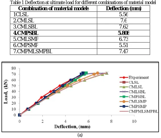
Beams were modelled and analysed using all the seven combinations. Deflections obtained for each combination is shown in Fig.3. Load-deflection graph (Fig.4) was plotted and deflections at ultimate load for different combinations of material models were tabulated (Table 1) for all the 7combinations. From the load deflection graph, we can see that finite element program using microplane model is giving comparable as well as better results with that of experiment than simply using material models available in the software.
Table 1 Deflection at ultimate load for different combinations of material model
Combination of material models Deflection (mm)
1CLSL 5.56 2.CMLSL 7.6 3.CMLSBL 7.62
4.CMPSBL 5.808
5.CMLSMP 6.73 6.CMPSMP 5.51 7.CMPMLSMPBL 7.47
(a)
Fig.4 (a) Load deflection graph for different combinations of material models
Table 1 shows the deflections at ultimate loads for different cases as well as the experimental deflection. Tabular data also confirms that beams modelled using microplane model is giving comparable results with that of experiment and better results when compared to using material models available in the finite element software alone. And the analysis with microplane model used only for concrete is giving the closest result to that of experiment towards the ultimate load since deflection at ultimate load from experiment = 5.8mm (P.M Shanmughavadivu,2013) , even though combination with microplane model used for both concrete and steel is giving closest results in the initial region. Microplane model when used for both concrete and steel obtained an average variation of only 9.94% with experiment. Percentage variation of deflection at ultimate load, when microplane model used for concrete is only 0.14%.
V. CONCLUSION
Microplane modelling has been successfully used in ANSYS finite element programme for analysing RC beams. Analysis using microplane model for concrete is giving the closest result to that of experiment towards the ultimate load (only 0.14%variation with that of experiment).Microplane model when used for both concrete and steel showed better simulation in the initial region ie, it obtained an average variation of only 9.94% with experiment.
REFERENCES
[1] ANSYS, ANSYS 15.0 Manual Set, ANSYS Inc., South point, 275 Technology Drive, Canonsburg, PA 15317, USA
[2] Beleandez Tarsicio, Cristian Neipp and Augusto Beleandez, “Numerical and Experimental Analysis of a Cantilever Beam: a Laboratory Project to Introduce Geometric Nonlinearity in Mechanics of Materials”, International Journal of Engineering Education, Volume 19, September, 2003
[3] Ellen Kuhl, Gian Antonio D'Addetta, Hans J. Herrmann, Ekkehard Ramm, “A comparison of discrete granular material models with continuous microplane formulations”, International Journal of Engineering Education, 2000
[4] Hayder Qais Majeed, “Nonlinear Finite Element Analysis of Steel Fiber Reinforced Concrete Deep Beams With and Without Opening”, Journal of Engineering, Volume 18, December,2012
[5] Honggun Park and Hakjun Kim, “Microplane Model for Reinforced-Concrete Planar Members in Tension-Compression”, ASCE Journal of Structural Engineering, Volume 129, March, 2003
[6] Iulia C. Mihai,“Micromechanical constitutive models for cementitious composite materials”, Cardiff University, January 2012
[7] Josko Ozbolt, Zdenko Tonkovic and Luka Lackovic, “Microplane Model for Steel and Application on Static and Dynamic Fracture”, ASCE Journal of Engineering Mechanics, September, 2016
[8] Michael Leukart and Ekkehard Ramm, “Identification and Interpretation of Microplane Material Laws”, ASCE Journal of Engineering Mechanics, Volume 132, March, 2006
[9] Moufaq Noman Mahmoud, “ Design and Numerical Analysis of Reinforced Concrete Deep Beams”, Delft University of Technology, October, 2007
[10] N Subramanian, “Limiting reinforcement ratios for RC flexural members”, The Indian Concrete Journal, September 2010
[11] P. Bazant, D. Adley, Carol, Milan Jirasek and Caner, “Large-Strain Generalization of Microplane Model for Concrete and Application”, ASCE Journal of Engineering Mechanics, Volume 126, September, 2000
[12] P.Bazant, D.Adley, Carol, Milan Jirasek and Caner, “Microplane Model M4 for Concrete I: Formulation with Work-Conjugate Deviatoric Stress”, ASCE Journal of Engineering Mechanics, Volume 126, September, 2000
[13] P. Bazant, Ferhun C and Caner, “Microplane Model M4 for Concrete. II: Algorithm and Calibration”, ASCE Journal of Engineering Mechanics, Volume 126, September, 2000
[14] P.Bazant and Josko Ozbolt, “Compression Failure of Quasi brittle Material: Nonlocal Microplane Model”, ASCE Journal of Engineering Mechanics, Volume 118, March, 1992