555-660-140
Comcode 108135963
Issue 1
February 1998
Communications System
Release 6.0
Notice
Every effort was made to ensure that the information in this book was complete and accurate at the time of printing. However, information is subject to change.
See Appendix A, “Customer Support Information,” for important information. It follows Maintenance and Troubleshooting in this binder.
Your Responsibility for Your System’s Security
Toll fraud is the unauthorized use of your telecommunications system by an unauthorized party, for example, persons other than your company’s employees, agents, subcontractors, or persons working on your company’s behalf. Note that there may be a risk of toll fraud associated with your telecommunications system, and if toll fraud occurs, it can result in substantial additional charges for your telecommunications services.
You and your system manager are responsible for the security of your system, such as programming and configuring your equipment to prevent unauthorized use. The system manager is also responsible for reading all installation, instruction, and system administration documents provided with this product in order to fully understand the features that can introduce risk of toll fraud and the steps that can be taken to reduce that risk. Lucent Technologies does not warrant that this product is immune from or will prevent unauthorized use of common-carrier telecommunication services or facilities accessed through or connected to it. Lucent Technologies will not be responsible for any charges that result from such unauthorized use. For important information regarding your system and toll fraud, see Appendix A, “Customer Support Information.”
Federal Communications Commission Statement
This equipment has been tested and found to comply with the limits for a Class A digital device, pursuant to Part 15 of the FCC Rules. These limits are designed to provide reasonable protection against harmful interference when the equipment is operated in a commercial environment. This equipment generates, uses, and can radiate radio frequency energy and, if not installed and used in accordance with the instruction manual, may cause harmful interference to radio communications. Operation of this equipment in a residential area is likely to cause harmful interference, in which case the user will be required to correct the interference at his own expense. For further FCC information, see Appendix A, “Customer Support Information.”
Canadian Department of Communications (DOC) Interference Information
This digital apparatus does not exceed the Class A limits for radio noise emissions set out in the radio interference regulations of the Canadian Department of Communications.
Le Présent Appareil Numérique n’émet pas de bruits radioélectriques dépassant les limites applicables aux appareils numériques de la classe A préscrites dans le réglement sur le brouillage radioélectrique édicté par le ministère des Communications du Canada.
Trademarks
ACCULINK, Accunet, MERLIN, MERLIN II, MERLIN LEGEND, Magic on Hold, MultiQuest, PassageWay, PARTNER, MLX-5, MLX-5D, MLX 10, MLX 10D, MLX 10DP, MLX 16DP, MLX 20L, and MLX 28D are registered trademarks and AUDIX Voice Power, FAX Attendant System, HackerTracker, and MERLIN MAIL, are trademarks of Lucent Technologies in the U.S. and other countries.
UNIX is a registered trademark of UNIX System Laboratories, Inc.
NORTEL is a registered trademark and DMS is a trademark of Northern Telecom. MCI, Prism, and Vnet are registered trademarks of MCI Communications Corp. Novell and NetWare are registered trademarks of Novell Corp.
For more information about Lucent Technologies documents, refer to the section entitled, ”Related Documents” in “About This Book.”
Support Telephone Number
In the continental US, Lucent Technologies provides a toll-free customer helpline 24 hours a day. Call the Lucent Technologies Helpline at 1 800 628-2888 or your Lucent Technologies authorized dealer if you need assistance when installing, programming, or using your system. Outside the continental US, contact your local Lucent
Technologies authorized representative.
Lucent Technologies Corporate Security
Whether or not immediate support is required, all toll fraud incidents involving Lucent Technologies products or services should be reported to Lucent Technologies Corporate Security at 1 800 821-8235. In addition to recording the incident, Lucent Technologies Corporate Security is available for consultation on security issues, investigation support, referral to law enforcement agencies, and educational programs.
Lucent Technologies Fraud Intervention
If you suspect you are being victimized by toll fraud and you need technical support or assistance, call BCS National Service Assistance Center at 1 800 628 2888.
Warranty
Lucent Technologies provides a limited warranty on this product. Refer to “Limited Warranty and Limitation of Liability” in Appendix A, “Customer Support Information,” which follows Maintenance and Troubleshooting in this binder.
Call: BCS Publications Center
Voice 1 800 457-1235 International Voice 317 322-6791
Fax 1 800 457-1764 International Fax 317 322-6849
Write: BCS Publications Center 2855 North Franklin Road Indianapolis, IN 46219-1385
Contents
Page iv
Contents
Contents iv
List of Figures v
List of Tables vii
About This Book ix
■ Intended Audience ix
■ Terms and Conventions Used x
■ Product Safety Labels xi
■ Security xii
■ Related Documents xiii
■ How to Comment on This Document xiv
System Programming and Maintenance 1
■ System Requirements 2
■ Installing the SPM Software 4
■ Connecting the PC 16
■ Accessing SPM 21
■ Using SPM 26
■ System Programming 61
■ Upgrading the System 69
■ Surrogate Mode Programming 91
List of Figures
Page v
List of Figures
1. Direct Local Connection 17 2. Direct Local Connection, PC More Than 50 ft. Away 18 3. Local Modem Connection 19 4. Remote Modem Connection 20 5. SPM Display 27
6. SPM Help 32
List of Figures
List of Tables
Page vii
List of Tables
1.
SPM Configuration File (ams.cfg) Options
12
2.
Function of PC Keys in SPM
29
3.
SPM Main Menu Options
31
4.
Backup Header: Release Number
33
5.
Board Types
39
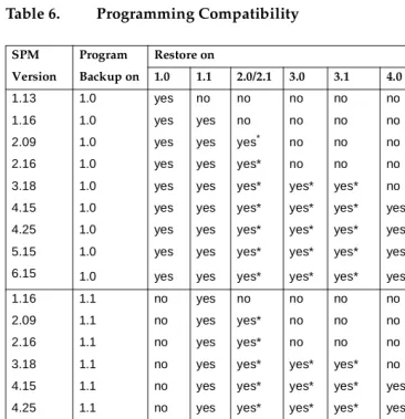
6.
Programming Compatibility
72
List of Tables
About This Book
Page ix Intended Audience
About This Book
System Programming and Maintenance (SPM) is a software tool develped specifically for the MERLIN LEGEND Communications system to allow programming, administration, and maintenance tasks to be done on a PC.
Intended Audience
This book is intended for anyone who uses a PC to perform programing or maintenance tasks for the communications system. It is especially aimed at system managers and support personel.
“Related Documents,” later in this section, provides a complete list of system documentation together with ordering information.
In the USA only, Lucent Technologies provides a toll-free customer Helpline (1
About This Book
Page x Terms and Conventions Used
Terms and Conventions Used
In this document, the terms in the following list are used in preference to other, equally acceptable terms for describing communications systems.
Lines, Trunks and Facilities
Facility is a general term that designates a communications path between a telephone system and the telephone company central office. Technically a trunk connects a switch to a switch, for example the MERLIN LEGEND
Communications System to the central office. Technically, a line is a loop-start facility or a communications path that does not connect two switches (for example, an intercom line or a Centrex line). However, in actual usage, the terms line and trunk are often applied interchangeably. In this book, we use line/trunk and lines/trunks to refer to facilities in general. Specifically, we refer to digital facilities. We also use terms such as personal line, ground-start trunk, Direct Inward Dialing (DID) trunk, and so on. When you talk to your local telephone company central office, ask them which terms they use for the specific facilities they connect to your system.
Some older terms have been replaced with newer terms. The following list shows the old term on the left and the new term on the right:
trunk module line/trunk module trunk jack line/trunk jack
station extension
station jack extension jack analog data station modem data station digital data station terminal adapter 7500B data station terminal adapter
analog voice and analog data station analog voice and modem data digital voice and analog data station MLX voice and modem data analog data only station modem data only station digital data only station terminal adapter only station 7500B data only station terminal adapter only station digital voice and digital data station MLX voice and terminal
About This Book
Page xi Product Safety Labels
MLX voice and 7500B data station MLX voice and terminal adapter station
Typographical Conventions
Certain type fonts and styles act as visual cues to help you rapidly understand the information presented:
Product Safety Labels
Throughout these documents, hazardous situations are indicated by an exclamation point inside a triangle and the word CAUTION or WARNING.
Example Purpose
It is very important that you follow these steps. You must attach the wristband before touching the connection.
Italics indicate emphasis.
The part of the headset that fits over one or both ears is called a
headpiece.
Italics also set off special terms.
If you press the Feature button on an MLX display telephone, the display lists telephone features you can select. A programmed Auto Dial button gives you instant access to an inside or outside number.
The names of fixed-feature,
factory-imprinted buttons appear in bold. The names of programmed buttons are printed as regular text.
Choose ([W3URJ from the display screen.
Plain constant-width type indicates text that appears on the telephone display or personal computer (PC) screen.
About This Book
Page xii Security
!
WARNING:
!
Warning indicates the presence of a hazard that could cause death or severe personal injury if the hazard is not avoided.
!
CAUTION:
Caution indicates the presence of a hazard that could cause minor personal injury or property damage if the hazard is not avoided.
Security
Certain features of the system can be protected by passwords to prevent unauthorized users from abusing the system. You should assign passwords wherever you can and limit knowledge of such passwords to three or fewer people.
Nondisplaying authorization codes and telephone numbers provide another layer of security. For more information, see Appendix A, “Customer Support Information” following Maintenance and Troubleshooting.
Throughout this document, toll fraud security hazards are indicated by an exclamation point inside a triangle and the words Security Alert.
!
Security Alert:
Security Alert indicates the presence of a toll fraud security hazard. Toll fraud is the unauthorized use of your telecommunications system by an unauthorized party (for example, persons other than your
About This Book
Page xiii Related Documents
Related Documents
In addition to this book, the documents listed below are part of the
documentation set. Within the continental United States, these documents can be ordered from the Lucent Technologies BCS Publications Center by calling 1 800 457-1235.
Document No. Title
System Documents
555-660-100 Customer Documentation Package
Consists of paper versions of System Manager’s Guide, Feature Reference, and System Programming.
555-660-110 Feature Reference 555-660-111 System Programming 555-660-112 System Planning 555-660-113 System Planning Forms 555-660-116 Pocket Reference 555-660-118 System Manager’s Guide 555-660-150 Network Reference
555-660-800 Customer Reference CD-ROM
Contains System Manager’s Guide, Feature Reference, System Programming, and Network Reference.
Telephone User Support
555-660-122 MLX Display Telephones User’s Guide
555-630-150 MLX-5D, MLX-10D and MLX-10DP Display Telephone Tray Cards (5 cards)
555-630-152 MLX-28D and MLX-20L Telephone Tray Cards (5 cards) 555-660-124 MLX-5 and MLX-10 Nondisplay Telephone User’s Guide 555-630-151 MLX-5 and MLX 10 Nondisplay Telephone Tray Cards
(6 cards)
555-630-155 MLX-16DP Display Telephone Tray Cards (5 cards) 555-660-120 Analog Multiline Telephones User’s Guide
555-660-126 Single-Line Telephones User’s Guide 555-660-138 MDC and MDW Telephones User's Guide
System Operator Support
About This Book
Page xiv How to Comment on This Document
How to Comment on This Document
We welcome your comments, both positive and negative. Please use the feedback form on the next page to let us know how we can continue to serve you. If the feedback form is missing, write directly to:
Documentation Manager Lucent Technologies 211 Mount Airy Road Room 2W226
Basking Ridge, NJ 07920
555-660-132 Analog Direct-Line Consoles Operator’s Guide 555-660-136 MLX Queued Call Console Operator’s Guide
Miscellaneous User Support
555-660-130 Calling Group Supervisor’s Guide 555-650-105 Data and Video Reference
Documentation for Qualified Technicians
555-660-140 Installation, Programming & Maintenance (IP&M) Binder
Consists of Installation, System Programming &
Maintenance (SPM), and Maintenance & Troubleshooting
Toll Fraud Security
System Programming and Maintenance
Page 1
System Programming and
Maintenance
The System Programming and Maintenance (SPM) software package offers an alternate method of programming the MERLIN LEGEND Communications System using a PC. This method frees the system programming console for other uses and also provides the additional functions listed below:
■ Backing up system programming information
■ Restoring system programming information from a backup
■ Converting system programming information from one release to another (part of the upgrade procedure)
■ Upgrading the communications system to a newer release
■ Printing, viewing, and storing reports
■ Programming the communications system remotely
■ Programming in surrogate mode
SPM runs on a DOS-based PC as a standalone program or on a UNIX System platform as part of Intuity, Integrated Solution II, or Integrated Solution III (IS II/III are discontinued products). It is available on a 3.5-inch diskette for DOS or UNIX, or on a 5.25 3.5-inch diskette for DOS.
NOTE:
SPM software can be used directly from the floppy disks on a DOS machine; however, if your PC has a hard disk, you should install SPM onto the hard disk.
System Programming and Maintenance
Page 2 System Requirements
For information about accessing SPM from the IS II/III application, refer to the following books:
■ Integrated Solution III System Manager’s Guide, order no. 555-601-010
■ Integrated Solution III Installation and Maintenance Guide, order no. 555-601-011
■ Integrated Solution II System Manager’s Guide, order no. 555-600-726
■ Integrated Solution II Installation and Maintenance Guide, order no. 555-600-720
System Requirements
To use SPM for system programming, you need the SPM diskette and an approved PC with version 3.3 (or later) of MS-DOS. At a minimum, your PC should support and include the following items:
■ At least 640 kbytes of RAM
■ A floppy disk drive that will accommodate the SPM diskette (3.5-inch or 5.25-inch)
■ A monochrome or color monitor
■ A serial port that can use either a DB-9 or DB-25 connector
■ For a DB-9 connector, use a 9-pin to 25-pin adapter to attach the 25-pin connector of the RS-232 interface cable.
System Programming and Maintenance
Page 3 System Requirements
Depending on how you connect the PC to the control unit, you also need the following items:
■ Direct local connection, if the PC is within 50 ft. of the control unit.
— Either a 355AF modular adapter (if there is a male connector on the interface cable) or a 355A modular adapter (if there is a female connector on the interface cable)
— A four-pair modular cord (D8W)
■ Direct local connection, if the PC is more than 50 ft. from the control unit.
— 355AF adapter
— EIA crossover cable
— Two Z3A2 Asynchronous Data Units (ADUs)
— ADU crossover cable
— 400B2 power adapter
— 2012D transformer
— BR1A-4P adapter and either a 102 connecting block or 103 connecting block
— 248B adapter
— eight-position wall jacks
— four-pair plug-ended cable
— D8W cords
— D6AP power cord
— EIA-23D cables
■ Modem (local or remote) connection
— A modem that supports 1200- or 2400-bps connections
System Programming and Maintenance
Page 4 Installing the SPM Software
NOTE:
SPM uses Interrupt 4 and I/O address 3F8 for COM1. It uses Interrupt 3 and I/O address 2F8 for COM2.
Installing the SPM Software
Before you install or run SPM, use GLVNFRS\ on a DOS PC (see your operating system guide) to make a backup copy of the SPM diskette and store the original in a safe place. Use the backup copy to run the installation program.
For installing SPM on a DOS PC, follow the appropriate instructions in the next section of this book.
NOTE:
If your PC does not have a hard disk, you do not need to run the installation program. Go to “Initializing the SPM Software.”
DOS Installation
Use the following procedure to install SPM on the hard drive of a DOS PC.
NOTE:
If you are updating SPM, you do not need to remove the current SPM files. The new files will overwrite your current SPM files.
Considerations
Review the following items before you begin the installation procedure.
The installation program automatically performs the following:
System Programming and Maintenance
Page 5 Installing the SPM Software
■ Checks the autoexec.bat and config.sys files. If either file is
write-protected, the installation is terminated and an error message is generated. SPM must make changes to these files.
■ Saves a copy of autoexec.bat as autoexec.old.
■ Saves a copy of config.sys as config.old.
■ If autoexec.bat has not already been configured for SPM, performs the following:
— Adds F?VSP to the path statement — Adds the line 6(7$06B3$7+ &
— Adds the background print command
35,17'351%806!18/
■ Adds the following line to config.sys if it is not already present
'(9,&( &?$16,6<6.
■ Copies the ansi.sys file from the floppy disk to c:\.
■ Creates the directory c:\spm.
■ Copies the following files from the floppy disk into c:\spm:
— spm.exe
— ams_hlp.eng (English language help file)
— ams_hlp.fre (French language help file)
— ams_hlp.spa (Spanish language help file)
■ Creates the following directories if they do not already exist:
— c:\spm\backup
— c:\spm\reports
System Programming and Maintenance
Page 6 Installing the SPM Software
■ Does one of the following:
— Creates the SPM configuration file c:\spm\ams.cfg, if it does not already exist. In this case, the ams.cfg file consists of only one line, in which the language attribute is specified: /$1* if you specified English or did not specify a language with the
LQVWDOO command;
— Modifies the ams.cfg file, if it already exists, by adding or changing the LANG value.
Follow the steps below to install SPM on the PC’s hard disk.
! Switch to Drive A, if it is not already the current drive.
$! appears on the screen.
! Insert the backup copy of the SPM diskette into Drive A.
! Type one of the commands shown below and press 1.
■ JOTUBMM ■ JOTUBMMGSFODI ■ JOTUBMMTQBOJTI
Because English is the default language, LQVWDOO and LQVWDOOHQJOLVK have the same result. If you do use the language argument (HQJOLVK, IUHQFK, or
VSDQLVK), you must type it in lowercase letters as shown. The command
LQVWDOO may be uppercase or lowercase.
! Wait for the message shown below to appear.
System Programming and Maintenance
Page 7 Installing the SPM Software
! Press any key to begin the installation.
When the installation is finished, the following message appears:
SPM HARD DISK INSTALLATION IS NOW COMPLETE YOU MUST REBOOT YOUR SYSTEM BEFORE USING SPM
! Remove the SPM diskette from Drive A and reboot your system.
The installation procedure is complete. Go to “Initializing the SPM Software.”
DOS Installation with Windows 95
Using DOS SPM with Windows 95 improves the interaction of SPM with the operating system as compared to Windows 3.x installation. For example, the interaction with the print driver is improved. If an online printer is not available when you try to print while using SPM, you see a message box explaining the problem. You can correct the problem by bringing the printer on-line and continuing, or you can cancel the print operation. SPM operation is not affected by the error message or the action you take to correct the problem.
Use the following procedure to install SPM. You do not need to remove the current SPM files. The new files automatically overwrite your current SPM files.
Considerations
Review the following items before you begin the installation procedure.
The installation program automatically performs the following:
■ If you typed LQVWDOO (the command for DOS installation) instead of
LQVWDO, checks if your PC has Windows 95 installed. If Windows 95 is detected, you see an error message that tells you to run the Instal95 program.
■ Creates the directory c:\spm if it does not already exist.
System Programming and Maintenance
Page 8 Installing the SPM Software
■ Runs the DOS SETVER command to set the version table for print.exe to 6.22. This is required to enable print.exe to run on Windows 95.
■ Creates an spm.bat file in the directory c:\spm. The spm.bat file contains the ams_path and print statements required to run SPM.
■ Unzips and copies the remaining files into the directory c:\spm.
■ Instructs you to refer to this document for details on using the PIF Editor to configure an SPM PIF file to work with the spm.exe file.
Installation
With Windows 95 running on your PC, follow these steps to install SPM on the PC’s hard drive:
1. Insert a backup copy of SPM in any floppy disk drive (usually the A drive).
2. Choose one of the following two methods to install SPM:
Method 1- Install DOS SPM with French, Spanish, or English Language:
a. Open a DOS Window from the Windows Explorer.
b. At the DOS prompt, switch to the drive with the backup copy of SPM diskette (usually the A drive).
c. At the DOS prompt, type one of the commands shown below and press 1
■ LQVWDORULQVWDOHQJOLVK ■ LQVWDOIUHQFK
■ LQVWDOVSDQLVK
NOTE:
Because English is the factory-set language, JOTUBM and
JOTUBM FOHMJTI have the same result. If you do use the
System Programming and Maintenance
Page 9 Installing the SPM Software
in lowercase letters as shown. The command JOTUBM may be in uppercase or lowercase letters.
Method 2- Install DOS SPM with French, Spanish, or English Language:
a. From the Windows Explorer, select the floppy drive that contains the backup copy of SPM diskette.
b. Select and run Instal95 (either by double clicking on the file name or single clicking on the file name and using the menu choice File:Open).
3. After you start DOS SPM installation using either method, the following message appears:
SPM WINDOWS 95 HARD DISK INSTALLATION PROGRAM Press any key to continue.
4. Press any key to begin the installation.
5. If your PC does not have a copy of PRINT.EXE in any directory listed in your system’s PATH environment, the following message appears:
Copying print.exe to directory c:\spm file(s) copied
WARNING - The application you are adding to the Windows version table may not have been verified by Microsoft in this version of Windows. Please contact your software vendor for information on whether this application will operate properly under this version of Windows. If you execute this application by instructing Windows to report a different
MS-DOS version number, you may lose or corrupt data, or cause system instabilities. In that circumstance, Microsoft is not responsible for any loss or damage. Version table successfully updated.
The version change will take effect the next time you restart your system.
System Programming and Maintenance
Page 10 Installing the SPM Software
SPM Note: The warning message seen above was produced by the SETVER command. This command was used in the SPM install program to set the proper version of PRINT.EXE file in the DOS version table. Please note that in Windows 95, running SETVER always produces the warning message seen above, even when the command is run properly.
******************************************************* Press any Key to continue . . .
6. Press any key to continue installation. When SPM installation is complete the following message appears:
Installation of SPM for DOS on your Windows 95 hard drive is now complete. For easy access to SPM from Windows 95, configure an SPM.PIF file. See the SPM Manual for details. Press any key to continue . . .
7. Press any key
— If you installed DOS SPM using Method 1 in Step 2, close the DOS Window by typing H[LW at the DOS prompt and pressing
1. If the window does not close, then the Close on Exit option for the DOS window is not set. In this case, close the window by clicking on the upper right window icon (the box with an x in it).
— If you installed DOS SPM using Method 2 in Step 2, the DOS window closes automatically.
8. If the print.exe file was copied to your PC in Step 5, you must reboot your PC.
9. You should now configure a PIF file for SPM. Use the instructions that follow
Configuring a PIF file for DOS SPM
System Programming and Maintenance
Page 11 Installing the SPM Software
Configure a PIF file for DOS SPM by doing the following:
1. In the Windows Explorer, select the SPM application file. Then select the menu item File:Properties. The screen that pops up will have tabs along the top.
2. In Program Tab:, put the following line in the Working Directory entry:
&?630
3. In Program Tab:, put the following line in the Batch File entry:
&?630?630%$7
4. In Program Tab:, make sure the Close on Exit checkbox is checked.
You can now double click on either the SPM application icon or the SPM “Shortcut to MS-DOS” icon to run SPM. When you quit SPM (by pressing the
Home key), the window closes automatically.
Hiding the spm.exe and spm.bat Files
If you want to hide the spm.exe and spm.bat files, use the following steps:
1. In the Windows 95 Explorer, select each file.
2. Click File from the menu bar, then select Properties.
3. In the Properties dialog box, click on the Hidden checkbox located under the General Tab in the Attributes section.
Initializing the SPM Software
System Programming and Maintenance
Page 12 Installing the SPM Software
The information you provide during the initialization process is written to the SPM configuration file (ams.cfg). If you need to change this information at some later time, you can do so in either of the following ways:
■ Use any of the options in Table 1 to change the information in ams.cfg.
■ Edit the ams.cfg file. (If you are unsure about editing the file, you can remove it. You are prompted to reinitialize the next time you invoke SPM. The file is created at that time.)
NOTE:
The DEBUG attribute is also specified in ams.cfg as '(%8* 2 (off), the default setting, or '(%8* (on). This attribute is used to enable the Escape-to-Shell feature of SPM, activated by pressing < + . To turn DEBUG on, you must edit the ams.cfg file; it is not part of the initialization process. The DEBUG attribute is for use by qualified service personnel only.
Table 1. SPM Configuration File (ams.cfg) Options
Option Use
TQN DPN Specifies COM1 as the serial communications port used by SPM
TQN DPN Specifies COM2 as the serial communications port used by SPM
TQN T Specifies modem speed of 1200 bps
TQN T Specifies modem speed of 2400 bps
TQN DPMPS Specifies color monitor
TQN NPOP Specifies monochrome monitor
TQN FOHMJTI Specifies English as the PC language
TQN GSFODI Specifies French as the PC language
System Programming and Maintenance
Page 13 Installing the SPM Software
Follow the steps below to perform the SPM initialization.
! Type TQNand press1to display the SPM Welcome screen shown
in Step 2.
■ 0BLFZPVSFOUSZBUUIF&!QSPNQUJGZPVS3&IBTBIBSE
EJTL
■ 0BLFZPVSFOUSZBUUIF$!QSPNQUJGZPVBSFVTJOHUIF
GMPQQZESJWF
! Press any key.
The screens shown in Steps 3 through 7 appear only if the system has not been initialized. Otherwise, the screen shown in Step 8 appears.
! Select the serial communications port used for SPM and press 1.
:HOFRPHWR630 X.XX = current version of SPM
7KH0(5/,1/(*(1' 6\VWHP3URJUDPPLQJ 0DLQWHQDQFH8WLOLW\ 3OHDVHSUHVVDQ\NH\ WRFRQWLQXH 9HUVLRQ;;;
&2003257 Type for serial port 1 (COM1).
&RPP Type for serial port 2 (COM2).
System Programming and Maintenance
Page 14 Installing the SPM Software
! Select the communications port speed and press 1.
! Respond to the color prompt and press 1.
! Select a language and press 1.
The language you select here becomes the SPM (PC) language.
6SHHG Type for 1200 bps.
Type for 2400 bps.
(QWHUVHOHFWLRQ
&2/25 Type Z if you have a color monitor.
(QWHUVHOHFWLRQ\Q Type Oif you do not have a color monitor.
/DQJXDJH Type for English.
(QJOLVK Type for French.
)UHQFK Type for Spanish.
System Programming and Maintenance
Page 15 Installing the SPM Software
! Review your selections.
■ To change any of the information shown, type and press 1. The screen shown in Step 3 appears. Repeat Steps 3 through 6.
■ To save the information shown, type - and press 1.
— If the PC is connected to the processor, the SPM Main Menu appears as shown in Step 8.
— If the PC is not connected, go to “Connecting the PC.”
! Press the function key that corresponds to the option you want.
NOTE:
The function keys shown on either side of the display are included here for quick reference. See “SPM Screens” for details on using the PC keys in SPM.
630&21),*85$7,21 x = the values entered for each
&RPP3RUW[ entry in Steps 3 through 6
6SHHG[ &RORU[
'HVLUHFKDQJH\Q"
6300DLQ0HQX 0HQX6HOHFW)XQFWLRQ
6\V3URJUDP 0DLQWHQDQFH
%DFNXS 5HVWRUH
%RDUGV 3DVV7KUX
3ULQW2SWV 3DVVZRUG
System Programming and Maintenance
Page 16 Connecting the PC
Connecting the PC
There are three ways to connect the PC to the control unit. Choose the method below that is most useful for your installation.
■ Direct local connection
■ Local modem connection
■ Remote modem connection
Direct Local Connection
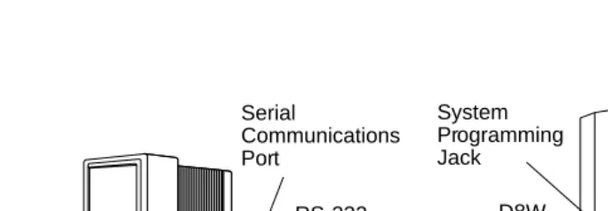
For a direct local connection, you must connect the PC to the system programming jack. This is the lower modular RS-232 jack on the processor module, as shown in Figure 1. (The upper jack is reserved for the SMDR printer.)
To connect a PC more than fifty feet from the control unit, see Figure 2.
For direct local connections, the system supports speeds of 1200 and 2400 bps.
NOTE:
System Programming and Maintenance
Page 17 Connecting the PC
Figure 1. Direct Local Connection
CAUTION POWER
ON
OFF
AG INPUT AG INPUT
FRFRGNDGND Turn off power before inserting or removing modules
408 GS/LS
44G
S o
r LS O
utside Lines/
8 Analog Telephones (A
TL)
40
8 008 M
LX
8 M
LX (Digita
l) T
ele
phones
012
PROCESSOR
System Programming Jack Serial
Communications Port
355AF Adapter
System Programming and Maintenance
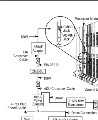
Page 18 Connecting the PC
Figure 2. Direct Local Connection, PC More Than 50 ft. Away CAUTION POWER ON OFF AG INPUT FRGND Turn off power before inserting or removing modules 408 G S /LS 4 4GS o
r LS O
uts ide L ines/ 8 A nalog T elephones (A TL) 40 8 00 8 M LX 8 M LX (D igital) T elephones 012 PROCESSOR AC Outlet D8W D8W D6AP Z3A2 ADU EIA-232-D DIW
102 or 103 Connecting Block 2012D-50M Transformer EIA-232-D BR1A-4P Adapter or 102 Connecting Block
or 103 Connecting Block
ADU Crossover Cable Control Unit Processor Module EIA Crossover Cable Z3A2 ADU SMDR Jack ADMIN Jack 355AF Adapter 8DW
or Direct Connection
Wall Jack
System Programming and Maintenance
Page 19 Connecting the PC
Local Modem Connection
For a local modem connection, you must use a modem (either connected to, or built into, the PC) to access the internal modem in the control unit. Connect the modem to an 012 or 016 module in the control unit, as shown in Figure 3.
The internal modem operates at speeds of 1200 and 2400 bps.
Figure 3. Local Modem Connection
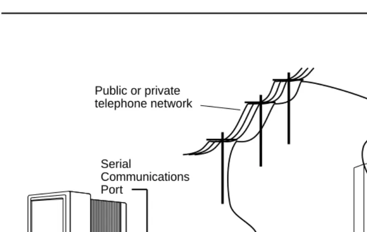
Remote Modem Connection
For a remote modem connection, you must use a modem (either connected to, or built into, the PC) to access the internal modem in the control unit. You must also use a dial-up connection, as shown in Figure 4. See “Accessing SPM” for details on accessing SPM with a remote modem connection.
The internal modem operates at speeds of 1200 and 2400 bps. CAUTION POWER ON OFF AG INPUT FRGND Turn off power before inserting or removing modules 408 G
S/LS44GS or LS O
uts
ide L
ines/
8 Analog Telephones (A
TL)
408 008 M
System Programming and Maintenance
Page 20 Connecting the PC
Figure 4. Remote Modem Connection
NOTE:
Remote access (modem connection) has priority over local access (direct connection), unless a backup or restore procedure is in progress through a direct local connection. If a modem connection is attempted while any other type of on-site programming is in progress (either at the system or at a directly-connected PC), the system sends a message to the on-site programmer. The message indicates that a modem connection is being established and the on-site programming session is terminated.
CAUTION POWER ON OFF AG INPUT FR GND Turn off power before inserting or removing modules 408 G S/LS 44G
S or LS O
utside L
ines/
8 Analog T
ele
phones
(ATL)
408 008 M
LX 8 MLX (Digita l) Telephones 012 PROCESSOR RS-232 Serial Communications Port Incoming trunk line Public or private
telephone network
System Programming and Maintenance
Page 21 Accessing SPM
Accessing SPM
The procedure for accessing SPM depends on whether your PC is connected to the control unit with a modem (either local or remote) or without a modem (direct). This section covers both of these access procedures.
With a Direct Local Connection
To access SPM when your PC is connected directly to the control unit, follow the steps below.
! Set up the appropriate physical connections between the PC and the
control unit.
See “Connecting the PC.”
! If you installed SPM on the hard disk of the PC, go to Step 5.
! If the PC does not have a hard disk, insert the SPM diskette into
Drive A.
! Type B and press 1.
$! appears on the screen.
! Type spm and press 1 to display the SPM Welcome screen shown
below.
:HOFRPHWR630 X.XX current version of SPM
System Programming and Maintenance
Page 22 Accessing SPM
! Press any key to display the SPM Main Menu shown below.
NOTE:
The function keys shown on either side of the display are included here for quick reference. See “SPM Screens” for details on using the PC keys in SPM.
■ If the SPM Main Menu does not appear or if the information on the screen is garbled, press any key again.
■ If the COM Port (communications port) screen appears instead of the SPM Main Menu, it indicates that the SPM software has not been initialized. See “Initializing the SPM Software.”
! To select an option, press the function key that corresponds to the
option you want. For example, to select /DQJXDJH press .
With a Local or Remote Modem
Connection
The method you use to access SPM by modem depends on whether you are programming on site (locally) or from a remote location.
■ If you are on site, the modem must be connected to an 012 or 016 module on the control unit. To establish a connection to the control unit’s internal modem, dial .
■ If you are at a remote location, do one of the following:
6300DLQ0HQX 0HQX6HOHFW)XQFWLRQ
6\V3URJUDP 0DLQWHQDQFH
%DFNXS 5HVWRUH
%RDUGV 3DVV7KUX
3ULQW2SWV 3DVVZRUG
System Programming and Maintenance
Page 23 Accessing SPM
— Place a call to the system on a Remote Access line, enter the barrier code (if required), and dial the code for the internal modem ().
— Place a voice call to the system using the line to which the modem is connected and ask the operator to transfer you to the modem (by pressing Transfer, dialing , then hanging up the telephone). When you hear the modem answer tone, switch to data mode.
Considerations
Review the following items before you begin the modem connection procedure.
Set the Programming Language
If you prefer to program in a language other than the current SPM language setting, see “Language.”
Modem Connections
You must make a data connection to a modem. The following modem dialing commands are for Hayes and Hayes-compatible modems. These may not be
the commands your modem usesrefer to the user guide that came with your modem for specific information.
■ If the PC is in the same location as the control unit, type .
■ If the PC is in a remote location and your system has activated the Remote Access feature, type the following and press 1:
— Without barrier codes type:
ATDT ; the remote access telephone number; and :. For example: $7'7: 1.
System Programming and Maintenance
Page 24 Accessing SPM
$7'7 ; the remote access telephone number; the barrier code preceded by a “W” and :. The barrier code in the example below is 555555.
For example: $7'7::1.
■ The password prompt appears on the screen when the connection is made. (You may have to press 1 more than once to get the password prompt.)
■ If the PC is in a remote location and your system has not activated the Remote Access feature, do the following:
— Use the main telephone number to place a voice call to the system on the line to which the modem is connected.
— Instruct the operator to transfer you to the modem (by pressing
Transfer, dialing , then hanging up the telephone).
— To put the modem on line, type $7+and press 1, then hang up the telephone.
NOTE:
If you enter a telephone number of fewer than 11 digits, you must end it with a pound sign (#).
To access SPM through a local or remote modem connection, follow the steps below.
! Set up the appropriate physical connections between the PC and the
System Programming and Maintenance
Page 25 Accessing SPM
! Type spmand press 1 to display the SPM Welcome screen shown
below.
If you wish to program in a language other than the current language set for SPM, see “Set the Programming Language.”
! Press any key to display a blank screen on which you can enter
modem commands. (You may have to press the key several times.)
! Make a data connection to the modem of the control unit.
See “Modem Connections.” When the connection is made, the password prompt appears as shown in Step 4.
! Type the SPM password to display the SPM Main Menu shown in
Step 6.
The password does not display as you type it.
:HOFRPHWR630 X.XX = current version of SPM
7KH0(5/,1/(*(1' 6\VWHP3URJUDPPLQJ 0DLQWHQDQFH8WLOLW\ 3OHDVHSUHVVDQ\NH\ WRFRQWLQXH
9HUVLRQX.XX
System Programming and Maintenance
Page 26 Using SPM
! To select an option, press the function key that corresponds to the
option you want. For example, to select /DQJXDJH press .
NOTE:
The function keys shown on either side of the display are included here for quick reference. See “SPM Screens” for details on using the PC keys in SPM.
Using SPM
This section describes how to use the SPM screens, SPM Help, and the SPM options listed below.
■ Backup
■ Boards
■ Browse
■ Convert
■ Language
■ Maintenance
■ Monitor
■ Pass-Thru
■ Password
■ Print Options
6300DLQ0HQX 0HQX6HOHFW)XQFWLRQ
6\V3URJUDP 0DLQWHQDQFH
%DFNXS 5HVWRUH
%RDUGV 3DVV7KUX
3ULQW2SWV 3DVVZRUG
System Programming and Maintenance
Page 27 Using SPM
■ Restore
■ System Programming
NOTE:
Some of the procedures described in this section should be performed by qualified service personnel only.
SPM Screens
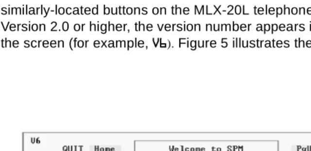
SPM screens simulate the system programming console. Each SPM screen includes a 7-line by 24-character console simulation window that corresponds to the display area of the MLX-20L telephone. To the right and left of this console simulation window are columns that list the keys corresponding to similarly-located buttons on the MLX-20L telephone. If you are working with Version 2.0 or higher, the version number appears in the upper left corner of the screen (for example, 9). Figure 5 illustrates the SPM display screen.
System Programming and Maintenance
Page 28 Using SPM
through , and through display on either side of the console simulation window. They represent the function keys to use when you select screen options. When a screen contains several choices, press the function key identified by the label next to your choice. (If you were programming on the console, you would press the telephone button next to your choice.)
Below the console simulation window are 20 simulated line buttons. The 20 line buttons can be selected using the arrow keys to position the cursor on the appropriate button. Using (the Inspect feature), you can determine the status of each line and the features programmed on each line according to the letter that appears next to the line number (see below).
On the PC screen, the letters 5 and * represent the ON state of the red and green LEDs, respectively, that are on the console. For example, if a line, trunk, or pool is assigned to a line button, on the console a green LED lights next to the button. On the PC screen, the letter * (for green) displays next to the button. Similarly, if a line, trunk, or pool is not assigned to a line button, neither
* nor 5 display next to the button on the PC screen. If a trunk is assigned to a pool, an 5 (for red) displays on the PC screen.
System Programming and Maintenance
Page 29 Using SPM
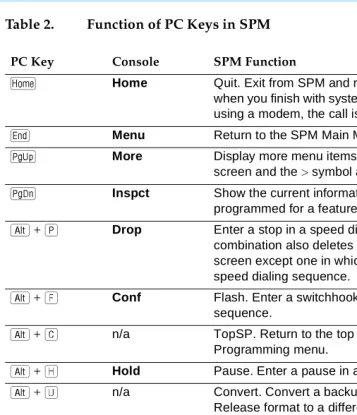
Table 2. Function of PC Keys in SPM
PC Key Console SPM Function
Home Quit. Exit from SPM and return to the DOS prompt when you finish with system programming. If you are using a modem, the call is disconnected.
Menu Return to the SPM Main Menu.
More Display more menu items (when there is another screen and the > symbol appears next to the key).
Inspct Show the current information that has been
programmed for a feature or button.
7%/%I Drop Enter a stop in a speed dialing sequence. This combination also deletes an entry in a field on any screen except one in which you are entering a speed dialing sequence.
7%/%P Conf Flash. Enter a switchhook flash in a speed dialing sequence.
7%/%Z n/a TopSP. Return to the top of the System Programming menu.
7%/%R Hold Pause. Enter a pause in a speed dialing sequence.
7%/%F n/a Convert. Convert a backup file from its original Release format to a different Release format.
7%/%- n/a Toggle modem speed between 1200 and 2400 bps.
<%/% n/a Help. Display a help screen about SPM operations. To exit from Help, press .
<%/% n/a Reset. Reset the communications port. For
example, if the information on the screen is garbled, try exiting from and then re-entering the screen. If the screen remains garbled, use < + to clear the screen and return to the SPM Welcome screen. Note that using < + drops the modem
connection.
<%/% n/a Browse. View print reports saved with Print Opts.
System Programming and Maintenance
Page 30 Using SPM
Table 2. Function of PC Keys in SPM
— Continued
SPM Main Menu Options
The SPM Main Menu provides access to system programming and to the SPM functions listed in Table 3.
PC Key Console SPM Function
<%/% n/a Escape to shell. To use this key sequence, you must set DEBUG=1 in the configuration file ams.cfg. You can then use this key sequence to execute DOS (or UNIX System) commands. To return to SPM, type exit.
1 Enter The 1%key on your PC can be used instead of
when (QWHU appears as a choice in the console simulation window.
3 Backspace The 3 key on your PC can be used instead of % (%DFNVSDFH) when it appears as a choice in the console simulation window.
9 Delete The 9 key on your PC can be used instead of % ('HOHWH) when it appears as a choice in the console simulation window.
%%# %%
System Programming and Maintenance
Page 31 Using SPM
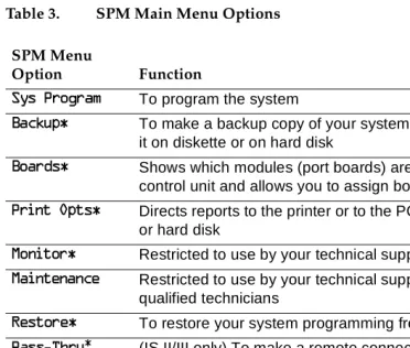
Table 3. SPM Main Menu Options
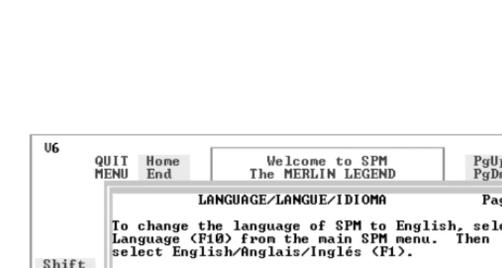
SPM Help
To access the SPM help screens, press < + .
To review the help screens press, and .
To return to the first help screen, press .
* SPM option only. Not available on the MLX-20L system programming console. To be used only by qualified service personnel.
SPM Menu
Option Function
6\V3URJUDP To program the system
%DFNXS To make a backup copy of your system programming and store it on diskette or on hard disk
%RDUGV Shows which modules (port boards) are in each slot of the control unit and allows you to assign boards to slots
3ULQW2SWV Directs reports to the printer or to the PC for storage on diskette or hard disk
0RQLWRU Restricted to use by your technical support organization
0DLQWHQDQFH Restricted to use by your technical support organization and qualified technicians
5HVWRUH To restore your system programming from diskette or hard disk
3DVV7KUX (IS II/III only) To make a remote connection, through the control unit, to an IS II/III PC to administer applications on the IS II/III PC.
3DVVZRUG To change the password for remote entry into the system.
/DQJXDJH To select a language (English, French, or Spanish) for the console simulation window on the PC. (There is also a
System Programming and Maintenance
Page 32 Using SPM
To exit from SPM help, press .
A typical help screen is shown in Figure 6.
Figure 6. SPM Help
Backup
System Programming and Maintenance
Page 33 Using SPM
NOTE:
Back up your system programming information on a regular basis. A current backup file allows you to quickly and easily restore your system, if the need arises.
Determining the Release Number
of a Backup File
If you have a backup diskette but do not know its release number, you may be able to find this information in the backup header. Beginning with later versions of Release 1.1, the backup file contains a backup header 128 bytes long. Approximately 59 of these bytes are currently used. Bytes 55 through 59 of the header contain the MERLIN Legend Communication System Release number, as shown in Table 4. (Release 1.0 and early versions of Release 1.1 do not contain this information in readable form.)
Table 4. Backup Header: Release Number
The release number is found in the first two bytes (four characters) of the identification number. For example, 0300 = 3.0, 0201 = 2.1.
If the backup file is compressed, you can read the header but you cannot read the data area following the header. Use UZQF[backup filename] to read the header on a DOS system or DBU [backup filename] to read the header on a UNIX System.
Note that the communication system release number, not the version number of SPM, reflects whether the backup file is compressed or uncompressed.
Release No. Build No. System Size Mode
Size 2 bytes 12 bytes 1 byte 1 byte
Examples 03 00 32 01 01 - Key
02 01 02 - Behind Switch
System Programming and Maintenance
Page 34 Using SPM
Release 1.0 backups are uncompressed and Release 1.1 and later backups are compressed. Uncompressed files take longer to restore.
Considerations
Review the following items before you begin the backup procedure:
■ The communications system does not have to be idle during backup; however, extension programming is blocked.
■ Any objects that are in a maintenance-busy state are stored in that state. When you restore system programming, these objects are busied out, even if they have since been released from the maintenance-busy state.
■ If you plan to store your backup file on a diskette, format a DOS diskette. (DOS formatting can be done on either a UNIX System PC or a DOS PC).
■ Uncompressed backup files are 100,000 to 210,000 bytes in size; compressed files are about 70,000 to 85,000 bytes.
■ Maintenance data (error logs and other data used by qualified service technicians) is not saved in the backup file.
Follow the steps below to perform the backup procedure.
! At the SPM Main Menu, press to select %DFNXS.
6300DLQ0HQX 0HQX6HOHFW)XQFWLRQ
6\V3URJUDP 0DLQWHQDQFH
%DFNXS 5HVWRUH
%RDUGV 3DVV7KUX
3ULQW2SWV 3DVVZRUG
System Programming and Maintenance
Page 35 Using SPM
! Follow the instructions for a floppy or a hard disk.
A second window appears which displays the *272)/233< and 0$.(1(: ),/( options and a directory listing for the C:\spm\backup directory.
■ If you are saving the backup file to a floppy disk, go to Step 3.
■ If you are saving the backup file to the hard disk, go to Step 4.
! Remove the SPM diskette and insert a formatted diskette. Use the
arrow keys to highlight *272)/233< and press 1.
After you press 1, the *272)/233< statement shown above changes to
*272+$5'',6. and the directory listing for A:\ is displayed. Continue with Step 4.
The screen displays the default name for the backup file (backup.ams).
! Specify a backup filename.
■ To select the default filename, use the arrow keys to highlight
EDFNXSDPV and press 1. Go to Step 6.
■ To enter a different filename, use the arrow keys to select 0$.(1(:
),/( and press 1. Go to Step 5.
0DNHDVHOHFWLRQIRU *272)/233<
WKH%$&.83ILOH 0$.(1(:),/(
0$.(1(:),/(ZLOO EDFNXSDPV
FUHDWHDQHZILOH ILOH
RQVHOHFWHGGHYLFH ILOH
System Programming and Maintenance
Page 36 Using SPM
! Type the new filename and press 1.
You can specify a drive letter with the filename but no path information.
! Verify that the filename chosen does not already exist.
The following screen appears only if the filename chosen already exists. Continue with Step 7 if this screen does not appear.
! Observe the backup status screen.
3UHVV(6&WR$ERUW If you are working from the floppy drive,
$? appears on the screen.
(QWHUILOHQDPH
GHIDXOWLVEDFNXSDPV
7KHILOHDOUHDG\H[LVWV
,I\RXFRQWLQXHWKHROG Press 0 to abort the backup. Go to
YHUVLRQZLOOEHGHOHWHG Step 1 to create a different backup file.
3UHVV(6&WRDERUW
RUFWRFRQWLQXH Press * to continue. Go to Step 7.
3UHVV(6&WR$ERUW filename = the backup filename specified
(VW%ORFNVYYY YYYY in Step 5
GJMFOBNF
System Programming and Maintenance
Page 37 Using SPM
SPM indicates the status of the backup by displaying the number of the last block received (xx ). Line 2 of the display screen shows the estimated number of blocks to be sent from the control unit (YYY YYYY). This line is blank if you are backing up from Release 1.0.
If you abort the backup, the partial backup file is deleted to prevent restoration from a corrupted file and you see the screen shown in Step 8.
When the backup is complete, you see the screen shown in Step 9.
! To abort the backup press 0 to return to the SPM Main Menu.
! When the backup is complete, press 1 to return to the SPM Main
Menu.
Boards
The Boards option allows qualified service personnel to add a board to the next available slot. The system must be idle to use this option. This option is not available from the system programming console.
3UHVV(6&WR$ERUW (VW%ORFNVYYY YYYY
ILOHQDPH
%$&.83,1352*5(66 ;02'(0$%2578VHU
%DFNXSVXFFHVVIXO xxx = total number of blocks received
3OHDVHSUHVV(QWHU WRVHHWKH0DLQ0HQX
System Programming and Maintenance
Page 38 Using SPM
The Boards option is also available in surrogate mode. In surrogate mode, you can assign trunk and extension modules (boards) to slots, even though the boards have not actually been installed. This type of board is referred to as a “phantom” or “null” board.
You cannot use the Boards option to change an actual board type. All boards assigned with the Boards option, including phantom boards, are cleared (unassigned) if you perform a board renumber (6\VWHP→%RDUG5HQXP).
NOTE:
You must assign phantom boards to higher slot numbers than those you assign to any real boards. If you assign a phantom board to a lower slot number than a real board, the control unit does not recognize the real board(s) that follow the phantom board.
NOTE:
If you remove a board but do not replace it, and then perform a board renumber, the control unit will not recognize any boards that follow the empty slot. You must reseat all of the boards to fill the empty slot before you perform the board renumber.
The Inspect function () lets you see which modules have been assigned to slots on the control unit. Note that both phantom boards and real boards display if you use the Inspect function. To see only real board assignments, you must print the System Information report:
6\VWHP→More→3ULQW→6\V6HWXS.
System Programming and Maintenance
Page 39 Using SPM
Table 5. Board Types
Follow the steps below to assign modules. Board Type Description
/65 4 loop-start line jacks with 4 touch-tone receivers
*/5 4 ground-start/loop-start line jacks with 4 touch-tone receivers
/6 8 loop-start line jacks
*/,' 8 ground-start/loop-start line jacks with Caller ID capability available on the loop-start lines and 2 touch-tone receivers
*/6 8 ground-start/loop-start line jacks
/6$ 4 loop-start line jacks and 8 ATL analog extension jacks
*/$ 4 ground-start/loop-start line jacks and 8 ATL analog extension jacks
*/0 4 ground-start/loop-start line jacks and 8 MLX extension jacks (16 endpoints)
$7/ 8 analog extension jacks
0/; 8 MLX-20L extension jacks (16 endpoints)
75237 12 tip/ring extension jacks with 2 touch-tone receivers or 008 OPT jacks
75 16 tip/ring extension jacks with 4 touch-tone receivers
',' 8 DID trunk jacks with 2 touch-tone receivers
( 0 4 E&M tie trunk jacks
' 1 DS1 jack (24 channels)
System Programming and Maintenance
Page 40 Using SPM
! At the SPM Main Menu, press to select %RDUGV.
! Press the function key that corresponds to the module you want to
select.
If the module you want to assign is not shown on the first screen of the Boards menu, press to display the next menu screen.
! Type the control unit slot number (01 through 17) in which the module
is to be installed. 6300DLQ0HQX 0HQX6HOHFW)XQFWLRQ
6\V3URJUDP 0DLQWHQDQFH
%DFNXS 5HVWRUH
%RDUGV 3DVV7KUX
3ULQW2SWV 3DVVZRUG
0RQLWRU /DQJXDJH
%RDUGV! %RDUGV
0DNHDVHOHFWLRQ 0DNHDVHOHFWLRQ
/6$ /6 ( 0755
75237 $7/ */$*/,'
',' 0/; '%5,
*/6 */5 */0
([LW /65 ([LW
PRGXOHQDPH module name = option selected in Step 2
(QWHUVORWQXPEHUV
System Programming and Maintenance
Page 41 Using SPM
! Assign or remove the module from the slot entered in Step 3.
To remove the module type from the specified slot number, press ('HOHWH).
The Boards menu reappears.
To assign the module type to the specified slot number and assign that same module type to another slot, press (1H[W).
To assign the module type to the specified slot number and assign a different module type to another slot, press ((QWHU).
To terminate the procedure and assign a different module, press
(([LW) and repeat Steps 2 through 4.
To view types of modules assigned to all slots, press (,QVSHFW).
! Save your entry.
Select ([LW.
The programming session terminates and the system restarts.
Browse
The Browse option allows you to browse through reports saved in the Reports directory (\spm\reports) on the hard disk of the PC or on a floppy.
PRGXOHQDPH module name = option selected in Step 2
(QWHUVORWQXPEHUV nn = slot entered in Step 3
OO
'HOHWH
%DFNVSDFH1H[W
System Programming and Maintenance
Page 42 Using SPM
! At the SPM Main Menu press < +.
FILENAME.XXX and FILENAME.YYY from the \spm\reports directory
! Use the arrow keys to highlight the source (hard disk or floppy) from
which you want to view the reports and press .
A list of the current reports appears.
! Use the arrow keys to highlight the report you want to view and
press.
The report appears.
■ To view the next page of a report, press . ■ To view the previous page of a report, press . ■ To return to the beginning of a report, press .
■ To exit from the Browse option and return to the SPM Main Menu, press 0.
Convert
The Convert option (which can be used remotely) simplifies upgrading from an earlier release to a later release of the communications system. (See
“Upgrading the Communications System.”) This procedure should be done only by qualified service personnel.
*272)/233<
3OHDVHHQWHUILOHQDPH ),/(1$0(.;;;
),/(1$0(.<<<
System Programming and Maintenance
Page 43 Using SPM
Convert uses two files: the existing backup file (the “convert from” file) and the converted file (the “convert to” file), which is created when you run the Convert option. The converted file contains system programming information in an uncompressed form. The “convert from” file is unchanged. Because uncompressed files take longer to process than compressed files, you may want to restore this uncompressed backup to the old control unit and then create a new backup. This new backup is in compressed form and does not have to be converted. For more information about compressed and
uncompressed files see “Backup.”
To convert system programming to Release 6.0 format, Version 6.15 of SPM is required. This version can be easily identified by the version number, 9, in the upper left corner of the screen.
Help screens are available to guide you through the Convert procedure. See “SPM Help.”
Before you use the Convert option, you must complete the following tasks:
■ If your PC has a hard disk, install the appropriate version of the SPM software. See “Upgrading the System.”
■ Back up system programming. See “Backup.”
■ Make sure you know the name of the backup file that you have created.
NOTE:
Once the actual file conversion begins, you cannot stop the process; pressing 0 has no effect.
System Programming and Maintenance
Page 44 Using SPM
! At the SPM Main Menu, press 7 + F to begin the conversion.
! Follow the instructions for a floppy or a hard disk.
A second window appears which displays the *272)/233< option and a directory listing for the C:\spm\backup directory.
■ If the backup file is stored on a floppy disk, go to Step 3.
■ If the backup file is stored on a hard disk, go to Step 4.
! Use the arrow keys to highlight *272)/233< and press 1.
FILENAME.XXX and FILENAME.YYY are from the \spm\backup directory.
6300DLQ0HQX 0HQX6HOHFW)XQFWLRQ
6\V3URJUDP 0DLQWHQDQFH
%DFNXS 5HVWRUH
%RDUGV 3DVV7KUX
3ULQW2SWV 3DVVZRUG
0RQLWRU /DQJXDJH
*272)/233<
3OHDVHVHOHFWILOHQDPH ),/(1$0(;;;
WRFRQYHUWIURP ),/(1$0(<<<
WKHQSUHVV(QWHU
System Programming and Maintenance
Page 45 Using SPM
After you press 1, the *272)/233< statement shown above changes to
*272+$5'',6. and a directory listing from the root directory of the floppy disk appears. Go to Step 4.
FILENAME.XXX and FILENAME.YYY are from the root directory of the disk in Drive A.
! Use the arrow keys to highlight the name of the backup file to be
con-verted and press 1.
■ If the backup file you select is a 6.0 backup, it can not be converted and the following message appears:
)LOHKDVDOUHDG\EHHQFRQYHUWHG 3UHVV(QWHUWRFRQWLQXH
Press 1 to select another filename, or press 0 to abort the convert procedure.
■ If the backup file you select can be converted, go to Step 6.
! Observe the updated file selection screen and press 1.
*272+$5'',6.
3OHDVHVHOHFWILOHQDPH ),/(1$0(;;;
WRFRQYHUWIURP ),/(1$0(<<<
WKHQSUHVV(QWHU
3UHVV(6&WRDERUW
FILENAME.XXX =the backup filename
3OHDVHVHOHFWILOHQDPH selected in Step 4
WRFRQYHUWIURP N = drive
WKHQSUHVV(QWHU
System Programming and Maintenance
Page 46 Using SPM
! If converting from Release 1.0 or 1.1, select the CONVERT TO release.
To convert from Release 1.2, 2.0, or 2.1 go to Step 7.
The screen below appears when converting from Release 1.0 or 1.1.
! Follow the instructions for a floppy or a hard disk.
■ If the CONVERT TO file will be saved to a floppy disk, go to Step 8.
■ If the CONVERT TO file will be saved to the hard disk, go to Step 9.
! Use the arrow keys to highlight *272)/233< and press 1.
3OHDVHHQWHU\RXU All characters must be entered as they
&219(5772UHOHDVH appear on the screen, including the
DQGSUHVV(17(5 decimal point.
L L
(QWHUQXPEHUYY
3OHDVHVHOHFWILOHQDPH *272)/233<
WRFRQYHUWWRRUVHOHFW 0$.(1(:),/(
1(:),/(WRFUHDWHDQHZ ),/(1$0(;;;
ILOHRQVHOHFWHGGULYH ),/(1$0(<<<
System Programming and Maintenance
Page 47 Using SPM
After you press 1, the *272)/233< statement shown above changes to
*272+$5'',6. and the directory listing from the root directory of the disk in Drive A appears. Continue with Step 9.
! Specify a filename for the converted file.
■ Highlight the name of the file you want to convert to, press 1, and go to Step 11.
■ To enter a different filename, use the arrow keys to select 0$.(1(:
),/( and press 1.
! Enter the new filename and press 1.
3OHDVHVHOHFWILOHQDPH *272+$5'',6.
WRFRQYHUWWRRUVHOHFW 0$.(1(:),/(
1(:),/(WRFUHDWHDQHZ ),/(1$0(;;;
ILOHRQVHOHFWHGGULYH ),/(1$0(<<<
(QWHU)LOHQDPH
3UHVV(6&WRDERUW
3OHDVHVHOHFWILOHQDPH
WRFRQYHUWWRRUVHOHFW
1(:),/(WRFUHDWHDQHZ ILOHRQVHOHFWHGGULYH (QWHU)LOHQDPH $?GJMFOBNFOFX
System Programming and Maintenance
Page 48 Using SPM
The converted file cannot have the same name as the file from whch you converted. If you specify the same filename, the following screen appears:
Press 1 and repeat this step.
! Check the updated file screen and press 1.
Observe the conversion progress screen.
When the conversion completes, the screen shown in Step 13 appears.
! Press any key to return to the SPM Main Menu.
7KHILOHVHOHFWHGWR FRQYHUWWRLVWKHVDPH DVWKHILOHVHOHFWHGWR FRQYHUWIURP3OHDVH FKRRVHDGLIIHUHQWILOH
3UHVV(QWHUWRFRQWLQXH
3OHDVHVHOHFWILOHQDPH FILENAME.NEW = name entered in
WRFRQYHUWWRRUVHOHFW Step 10
1(:),/(WRFUHDWHDQHZ N = drive
ILOHRQVHOHFWHGGULYH (QWHU)LOHQDPH 1),/(1$0(1(: GHIDXOWLV5(6725(1(:
&219(56,21,1352*5(66 FILENAME.XXX = name entered at Step 4
FILENAME.NEW = name entered at
&RQYHUWLQJ)URP Step 10
1),/(1$0(;;; N = drive
System Programming and Maintenance
Page 49 Using SPM
Language
A language attribute in the SPM configuration file \spm\ams.cfg (DOS version) or
/usr/ams/ams.cfg (UNIX System version) specifies whether SPM menus, pop-up windows, and other messages are presented in English, French, or Spanish. A second language selection option affects messages from the control unit to SPM and controls the display on the console simulation window for the duration of the session. These two language options operate
independently of each other.
The following discussion refers to the language specified in the SPM
configuration file as the PC language and the language used by the control unit as the console window language.
PC Language
During SPM installation, you select a language that is recorded in the SPM configuration file. Any time thereafter, SPM can be started with the -loption to specify a different language, using one of the following command lines:
■ TQN MFOHMJTI ■ TQN MGSFODI ■ TQN MTQBOJTI
Note that the option is a lowercase letter L and not the number 1.
Use of the O option changes the language attribute in the ams.cfg file. The language specified becomes the new PC language, used whenever SPM is started without the O option.
Console Window Language
By default, the language used in the console simulation window is the language specified in the ams.cfg file; however, you can select a different language for this window for the duration of the current session.
System Programming and Maintenance
Page 50 Using SPM
! At the SPM Main Menu press %to select /DQJXDJH.
! Press the function key that corresponds to your language selection.
The Display Language screen reappears, with the language you selected.
! Press to return to the SPM Main Menu or select another language.
Maintenance
!
CAUTION:
This option is for use by qualified technicians onl