Pipeline Implementation of Secure Hash Algorithm
(SHA-l) for Cryptographic Application in
Network Security
Mohamed KhaJil Hani Ahmad
Zoo
Sha'ameri Chong Wei Sheng Microelectronic& Computer Engineering Dept. (MiCE)Faculty of Electrical Engineering, Vniversiti Teknologi Malaysia,
80310 VIM
Skudai, Johor, Malaysia tel: 07-5505003 fax: 07-5566272 Email: [email protected]II DESIGN ARCHITECTURE
Pipelining is one of the design principles in high-speed hardware design, it exploits parallelisms for shorter clock cycle and higher throughput. Thus pipeline becomes the design principle of this SHA-I implementation [I].
M(1) (511 :01
M(n) [511:0) MD(1)
[159:01
~
M(2)SHA·1 (511:0)
MD(2) [159:0) initial seed(159:01
I
Message Digest, MD(159:0) input message,
M(i)(L:01
i=1,2,.. n 0<= L =~-1
s-1
Message Digest, MD(159:0)
Figure I: Flow of Iterative Operations in SUA-I Hashing
the overall system [I, 6]. In the paper entitled" SHA: A Design for Parallel Architectures?", Bosselaers, Govaerts and Vandewalle (1997) have shown that SHA-I offers a number of parallelisms- [I]. Based on their research, this paper proposes a pipeline architecture to exploit these parallelisms. The next section explains the pipeline SHA·I architecture. Section III investigates the pipeline operations of SHA-I. The simulation results and discussion are presented in section IV followed by the conclusion in section V.
I. INTRODUCTION
Hash function is a compression function that produces a digest of an input message. Cryptographic hash function is a one-way and collision free hash function. It is related to the notion of checksum, because it produces a checksum that is infeasible to be inverted [6]. The secure digest can be used for password storage, digital signature and authentication. Therefore cryptographic hash function is essential for network security, for instance e-cornmerce and remote access.
SHA-I [2] is a strong one-way hash function that is being employed in various standards, algorithms and products such as Pretty Good Privacy (PGP), Secure Hash Standard., Yarrow and Intel Pro/ I00 S server adapter. It is a block-chained digest algorithm, computed over the data in phases of 512-bit blocks. The first block is initialized with an 160-bit initial seed., the seed for the next block is generated from current block. Digest of the last block would be the 160-bit message digest of the entire stream. Conceptual flow of SHA-I hashing operation for an input message is depicted in Figure I while the SHA-I algorithm that is related to this paper is shown in AppendixA.
Abstract- This paper presents a pipeline
implementation of the Secure Hash Algorithm, SUA-I. This design is targeted for the Altera FlexlOKE50 Field Programmable Gate Array (FPGA) on a PCI card. All input output data interface and internal operations are performed in 32-bit width. The major advantage of this design is the higher throughput gained from the pipeline operations. therefore double speed performance is obtained compared to the equivalent software implementation on Sun SPARC 20/71. The higher throughput shows the potential of this design to support critical network security system, for example the digital signature in e-commerce.
Although SHA-I is a strong cryptographic hash function, its operation is rather computational demanding, thus cause a performance bottleneck in
One of the sixteen words from M(i)
II
K1, K2. K3. K4{32 i128
I
~'"~
it,
I
W(t K(t)
Reg2E 32
Reg1C I
-L...L..,...L_ _---.:L
..
•
Reg2A
Message digest(m) m=0,1..4 Figure 2. Datapatb Unit of Pipeline SHA-l
datapath unit (DPU) (Figure 2) are the main modules inthis design.
i. Datapatb Unit
The DPU consists of functional units and storage elements. The functional units are logical units, modulo 32 bit adders, multiplexers and barrel shifters; whereas registers are the storage elements. For each M(i) processing of SHA-I, M(i) is fed into DPU in the sequence sixteen 32-bit words and output message digest is fed out as sequence of five 32-bit words. Initialization vectors, IV_H's and constants, K' s are hardwired. Reg2' s stores the current H's for each processing block (Appendix A). Since these H's are used in the beginning and last few steps in each block. thus registers are needed for their storage. Regl keeps variables that are read and updated in each step. Msg_conv converts input messages, M(i) into eighty words, W(t) (Appendix A: equation a and b). Outputs of modulo-32 bit adders are pipe lined with RegP's. Logical units generate its 32-bit output according to the logical functions in Appendix A. A 4: I multiplexer selects output message digest.
For each block of input message M(i), the 80-step operations are performed in six rounds (Figure 3). Since the first to fourth round perform the same
operations (Appendix A: equation d), they are grouped as intermediate rounds. There are a few overlapping among these six rounds due to the available
parallelism~ in SHA·l and the pipeline architecture in this design. These overlapping reduce the number of clock cycles in pipeline SHA-I implementation.
Input message of block M(i)
[159:0J
1-Message digest of blockM(i)
[159:0]
Figure 3: Sequence of SHA-l operation
ii.Control unit
This design applies counter-based control unit to generate timing signals that coordinate the operationsin DPU. Although there are only eighty steps in SHA-l
algorithm, mod-84 cOUDter is used because of the latency in the pipeline operations. The state diagram of the CU is attached in Figure 6 (Appendix B). Initial round of fIrst message block follows the state diagram in Figure 6.a. After this initial round, all coming rounds in the every message block use common state diagram (Figure 6.b) as they have similar operations. As shown in Figure I, SHA-I processing of M(2) to M(n) takes the message digest of previous block and produces the seed or the final message digest, therefore they also share the same state diagram (Figure 6.b). The message digest is delivered starting from the fmal round of final message block (Figure 6.b). 160-bit message digest of entire message stream is completed within two steps after the processing of final block (Figure 6.c).
means they are available for the addition of the seeds in each message block (Appendix A).
i.Initial Round and Final Round Operations Two operations in the initial round are the initialisation of Regl's and Reg2's. ReglC and ReglD are always initialised with Reg2C and Reg2D respectively. For the first message block, Reg2's are initialised with the IV_H's. Inthe fmal round of every block, updated H's are stored in the Reg2's to become the message digest of current block and the seed of coming block, thus the Reg2's of coming block are initialised. (Appendix A: equation e).
ii.Intermediate Rounds Operations III PIPELINE OPERATIONS
Data dependency is one of the criteria in pipeline design. Since SHA-l is an iterative algorithm, data dependency between each step becomes the focus of our pipeline design. Critical path analysis on consecutive steps in SHA-I has shown that updated variableA in current step is to be circular shifted and added before becoming the next variable A [I]. In this design , since the fixed circular shifting is implemented through barrel shifter, the operations of modulo 32 addition become the only critical path operation to be pipelined.
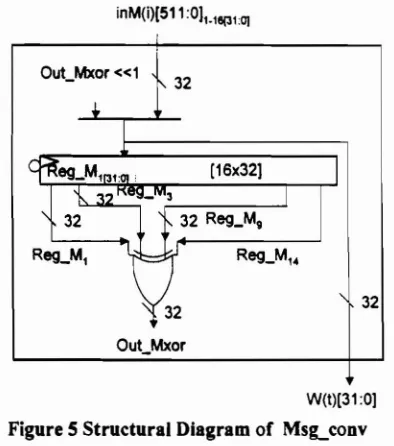
During the intermediate rounds (Figure 6.b), MS8-conv supplies Wet) by selecting either the 32·bit input message or the circular shifted data, which is the xor of four previous W(t)s (Appendix A: equation a and b), Incurrent design, register are used to store the these previous W(t)s. Since up to W(t-16) is needed, minimum registers required are sixteen (Figure 5). The Regl 's and RegP's are updated in the intermediate rounds (Figure 6.b) according to equation d (Appendix A). K(t) is selected from K's according to the sequence of rounds (Appendix A).
inM(i)[511:011' 18(31:0]
IV SIMULATION RESULTS& DISCUSSION W(t)[31:0]
Figure5Structural Diagram of MSlLconv
32 32
The timing simulation results are shown in Appendix C. The operating frequency is IOMhz on FlexlOKE50 at speed grade of -3 [4]. It takes a total of 84 clock cycles to compute the message digest of 512-bit message block, thus the speed of 61 Mbps is obtained. This speed is about double compared to the software implementation on Sun SPARC 20171 [5].
'-3 '-2
Figure 4: Pipelining Modulo-32 bits Adders in SUA-l
In SHA-l, There are a total of five 32-bit variables to be added. These additions are pipe lined as shown in Figure 4, parallel operations in one clock cycle are drawninthe same horizontal level and operations of the same step are shown between dotted lines.
Due to the latency of four clock cycles, some adders are not occupied at the fmal round, which
input message into 512-bit blocks, dividing each block into 32-bit inputs and cascading 5 words into a message digest. The design is coded in 800 lines of VHDL using behavioral description. On the Flex IOe50 FPGA, this implementation consumes hardware resources of 1191 logic cells including 879 flip-flops.
Parallelism of consecutive steps and block are exploited by pipeline architecture. To optimize the critical path operations, zero cost barrel shifters and hardware consuming carry look ahead adders are used.
V CONCLUSION
Beside achieves the security strength of SHA-I, this design also optimizes the parallelisms in the SHA-I using pipeline architecture and the design flexibility of Altera Flex10KE50. Positive preliminary result indicates its potential to support critical network security applications, such as e-commerce and secure file transfer. For current design, storage elements of Msg_conv are implemented in flip-flops, however for future design, embedded RAM in FlexlOKE50 would be used to obtain area efficiency. Future design will also use another 32-bit pipeline register to store the outputs of logical function for next immediate step in SHA-I. This extra pipeline should reduce the delay of feeding the logical function output to the adder.
ACKNOWLEDGEMENT
This research was supported in part by Altera Corp. (M) under research grant Vot. no. 68838. REFERENCE:
[I] Bosselaers, Govaerts, Vandewalle (1997), "SHA: A Design for Parallel Architectures?".
ftp://ftp.esat.kuleuven.ac.be/pub/COSICIb osselae/oaralle Los.gz
[2] National Institute of Standards and Technology( 1995) , "Secure Hash Standard", April 17, USA:
http://www.itl.nist.gov/fiosoubslfip 180-1.htm
[3] Schneier (1996), " Applied
Cryptography" USA: John Wiley& Sons [4] Altera Inc. (1999), "Device Data Book
1999"
[5] 1. Touch, "Performance Analysis of MD5", Proceedings of ACM
SIGCOMM'95, Compo Comm. Review, Vol.25, No.4, 1995, pp. 77-86. ftp://ftp.isi.edulpub/hpcc-papers/touch/sigcomm95.ps.Z
[6] K.S. McCurley (1994), "A Fast Portable Implementation of the Secure Hash AlgorithmIII",Technical Report SAND93-259I
[7] Sherigar, Mahadevan, Kumar, David(1997) "A Pipelined Parallel Processor to Implement MD4 Message Digest Algorithm on Xilinx FPGA" http://dlib.computer.orgiconferen/vlsid/82 24/pdti'82240394.pdf
APPENDIX
A. SHA-l Operations for Pipeline Architecture (following the standard notation in [2])
Partial initial round offirst block Before processing any blocks, the H'S are initialized.
Message conversion by Msg conv
Divide M(i) into 16 words W(O), W(I), . .. , W(l5), where W(O) is the left-most
word. (a)
S"n(X) = (X«n) OR (X» 32-n). For t = 16 to 79 let
W(t) = SI\I(W(t-3) XOR W(t-8)
XOR W(t-14) XOR W(t-16». (b)
Initial and intermediate rounds operations all blocks Let A = HO, B = HI, C = H2, D = H3,
E
=
H4. (c)For t=0 to 79 do
TEMP = SI\5(A)
+
f{t;B,C,D)+
E+
W(t)
+
K(t);E = D; D = C; C = SI\30(B); B = A;
A=TEMP; (d)
Final round of all blocks
Let HO = HO
+
A, HI = HI+
B, H2=H2 +C, H3=H3+
D,~=~+E
00
Message digest,
MD[159:0] = HO HI H2 H3 H4
Ouput of of logical unit and K(tl First round
f{t;B,C,D) = (B ANDC) OR «NOT B) AND D) K(t) = 5A827999 hex (KI)
(0 <=t <= 19)
Second round
f(t;B,C,D)= B XOR C XOR D K(t) = 6ED9EBA I hex(K2)
(20 <= t <= 39)
Third round
f{t;B,C,D) = (B AND C) OR (B AND D) OR (C AND D)
K(t) = 8FIBBCDC hex (K3) (40 <= t <= 59)
Forth round
f(t;B,C,D) = B XOR C XOR D K(t) = CA62ClD6 hex (K4) (60 <= t <= 79).
B. State Diagram of Pipeline SHA·l
i
from (b) final round~o
I
I
of final block~r-R-eg-28-.->-M-O-(1--')~:'-
R-eg-2A-.->M-O-(O-)""1,...
end I'goto(b)
I
'---_~_-l!l - . -:-:-_~-:---_---_-_---~I
(a) Partial initial round of (c) selecting message digest after first message block finish processing the final block
from (a) initial round of first mesaage block or
final round of intermediate message blocks
i
t=O
I_---N-O--<
I
adder": W(O)+K(?)
a> RegP"I
i
I
go to (e) select Imessage digest
i
I
I
i
~1 3
t
1280
I
•
ta8i
I
,
j~
Iadder2 : f(RegPi«30, Reg1 C. Reg10)+
I RegP3 => RegP2
Iadder1 : (Reg2A«S)+RegP2 => RegPi
IRegiC => Regi0
I
RegP1 « 30 => RegiCI
adder3 : Reg 10 +Reg2C :0> "Reg2C. "MO(2)Iadder2 : RegP1 and Reg2A :0> ·Reg2A
ta82
r
I
!adder3: RegiD
+Reg2D => "Reg2D. UMO(3)i
adder2: RegiA and Reg2B -> "Reg28i
adderi : (Reg2A«S) + RegP2 -> RegPi iReg1C:o> Regi0adder" : W(1)+K(1) -> RegP.. adder3 : Reg2E+RegP4 => RegP3 Reg20a>Reg10
Reg2C => RegiC
1=2
!
~
adder4 : W(2)+K(2)-::=7">""R07eg'::'ip"'4~---'
adder3 : Reg 10+RegP..:0>RegP3
adder2 : f(Reg2B. RegiC, Reg1D)+
RegP3 -> RegP2 RegiC => RegiD
Reg2B«30=> R,1C
adder" : '1'1(3) + K(3) => RegP" adder3 : RegiD+RegP" a> RegP3 adder2 : f(Reg2A. RegiC, Regi0) +
RegP3 a> RegP2
adderi : (Reg2A«S) + RegP2 -> RegPi RegiC a> Regi0
Reg2A« 30 => RegiC
(b) - partial initial round, intermediate rounds and final round of first message block
- complete rounds for intermediate and final message blocks
"ovel1apped operations from initial roundofintermediate and final message blocks10
initialiZe Reg2
"ovel1apped operations from (c)selecting output message digest
C. Timing Simulation Results of Pipeline SHA-l
,/
Specification ofthe timing
simltt~tlon
: ...,...,
... .•....
Using the test vector
from,d~e APP.~Jldli"A
of(21Message digests A9991'E36'4706816A BA3E257t 7850C26C 99000890 ..
....
Clock frequency= IOMhzon FlexlOKE50 speed-3.
Total clock cycles to process 512 bit message=84clock cycles Speed= 5121(84*0. Ius) bitls
=
61 MbpsFigure 7: Timing Simulation Results ofPipeJine SHA-l