Chapter 13
History of CAN (Controller Area Network)
• It was created in mid-1980s for automotive
applications by Robert Bosch.
• Design goal was to make automobiles more
reliable, safer, and more fuel efficient.
Layered Approach in CAN (1 of 3)
• Only the logical link and physical layers are described.
• Data link layer is divided into two sublayers: logical link control
(LLC) and medium access control (MAC).
– LLC sublayer deals with message acceptance filtering, overload
notification, and error recovery management.
– MAC sublayer presents incoming messages to the LLC sublayer and
accepts messages to be transmitted forward by the LLC sublayer.
– MAC sublayer is responsible for message framing, arbitration,
Layered Approach in CAN (2 of 3)
• The physical layer defines how signals are actually
transmitted, dealing with the description of bit timing, bit
encoding, and synchronization.
• CAN bus driver/receiver characteristics and the wiring
and connectors are not specified in the CAN protocol.
• System designer can choose from several different
Application Layer
CAN LAYERS
Data Link LLC sublayer
Acceptance filtering Overload notification Recovery management
MAC sublayer
Data encapsulation/decapsulation Frame coding (stuffing/destuffing) Medium access management Error detection
Error signaling Acknowledgement
Serialization/Deserialization
Supervisor
Fault Confinement
General Characteristics of CAN
(1 of 3)
• Carrier Sense Multiple Access with Collision
Detection (CSMA/CD)
– Every node on the network must monitor the bus
(carrier sense) for a period of no activity before trying
to send a message on the bus.
– Once the bus is idle, every node has equal
opportunity to transmit a message.
General Characteristics of CAN
(2 of 3)
• Message-Based Communication
– Each message contains an identifier.
• Identifiers allow messages to arbitrate and also allow each node to
decide whether to work on the incoming message.
• The lower the value of the identifier, the higher the priority of the
identifier.
– Each node uses one or more filters to compare the incoming
messages to decide whether to take actions on the message.
– CAN protocol allows a node to request data transmission from
General Characteristics of CAN
(3 of 3)
• Error Detection and Fault Confinement
– The CAN protocol requires each node to monitor the
CAN bus to find out if the bus value and the
transmitted bit value are identical.
– The CRC checksum is used to perform error checking
for each message.
– The CAN protocol requires the physical layer to use
bit stuffing to avoid long sequence of identical bit
value.
Types of CAN Messages
(1 of 2)
• Data frame
• Remote frame
• Error frame
Types of CAN Messages
(2 of 2)
• Two states of CAN bus
Start of Arbitration Control Data CRC ACK End of Data Frame
Interframe space
Interframe space or overload frame
Data Frame
Start of Frame
• A single dominant bit to mark the beginning of a
data frame.
Start of frame 11 bit Identifier RTR
Arbitration field Control field Interframe
space
Figure 13.3 Arbitration field
IDE r0 DLC
(a) standard format
Start of
frame 11-bit identifier (b) extended format
SRR IDE 18-bit identifier RTR r0 r1 DLC Arbitration field Control field
Arbitration Field
•
There are two formats for this field: standard format and extended format.
Control Field Arbitration
field or CRC fieldData field IDE/r1 r0 DLC3 DLC2 DLC1 DLC0
reserved bits Data length code
Control Field
• Contents are shown in figure 13.4.
• The first bit is IDE bit for the standard format but
is used as reserved bit r1 in extended format.
• r0 is reserved bit.
Data Field
CRC field
CRC sequence CRC delimiter Data or
Control field ACK
Figure 13.5 CRC field
CRC Field
• It contains the 16-bit CRC sequence and a CRC
delimiter.
ACK Field
• Consists of two bits
• The first bit is the
acknowledgement bit
.
– This bit is set to recessive by the transmitter, but will
be reset to dominant if a receiver acknowledges the
data frame.
Remote frame
Start of frame
arbitration field
Control field
CRC field
ACK field
End of frame Interframe
space
Interframe space or overload
frame
Remote Frame
• Used by a node to request other nodes to send
certain type of messages
• Has six fields as shown in Figure 13.7
– These fields are identical to those of a data frame with
the exception that the RTR bit in the arbitration field is
Error frame
Interframe space or
Overload frame Data
frame
Error Frame
• This frame consists of two fields.
– The first field is given by the superposition of error flags contributed
from different nodes.
– The second field is the error delimiter.
• Error flag can be either active-error flag or passive-error flag.
– Active error flag consists of six consecutive dominant bits.
Overload flag
Superposition of
Overload delimiter Overload frame
Interframe space or
Overload frame End of frame or
Error demiliter or Overload delimiter
Overload Frame
• Consists of two bit fields: overload flag and overload delimiter
• Three different overload conditions lead to the transmission of the
overload frame:
– Internal conditions of a receiver require a delay of the next data frame or
remote frame.
– At least one node detects a dominant bit during intermission.
– A CAN node samples a dominant bit at the eighth bit (i.e., the last bit) of
an error delimiter or overload delimiter.
• Format of the overload frame is shown in Figure 13.9.
• The overload flag consists of six dominant bits.
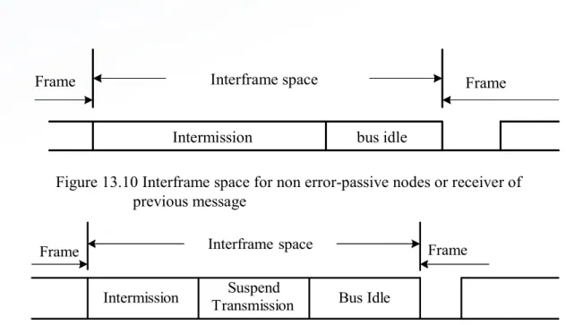
Interframe space
Intermission bus idle
Frame Frame
Figure 13.10 Interframe space for non error-passive nodes or receiver of previous message
Interframe Space (1 of 2)
• Data frames and remote frames are separated from preceding
frames by the interframe space.
• Overload frames and error frames are not preceded by an
interframe space.
Interframe Space
(2 of 2)
• The intermission subfield consists of three
recessive bits.
• During intermission no node is allowed to start
transmission of the data frame or remote frame.
• The period of bus idle may be of arbitrary length.
• After an error-passive node has transmitted a
Message Filtering
• A node uses filter (s) to decide whether to work
on a specific message.
• Message filtering is applied to the whole
identifier.
• A node can optionally implement mask registers
that specify which bits in the identifier are
Bit Stream Encoding
• The frame segments including start-of-frame, arbitration field, control
field, data field, and CRC sequence are encoded by bit stuffing.
• Whenever a transmitter detects five consecutive bits of identical
value in the bit stream to be transmitted, it inserts a complementary
bit in the actual transmitted bit stream.
• The remaining bit fields of the data frame or remote frame (CRC
delimiter, ACK field and end of frame) are of fixed form and not
stuffed.
• The error frame and overload frame are also of fixed form and are
not encoded by the method of bit stuffing.
• The bit stream in a message is encoded using the non-return-to-zero
(NRZ) method.
Errors
(1 of 3)
• Error handling
– CAN recognizes five types of errors.
• Bit error
– A node that is sending a bit on the bus also monitors the bus.
– When the bit value monitored is different from the bit value being
sent, the node interprets the situation as an error.
– There are two exceptions to this rule:
Errors
(2 of 3)
• Stuff error
– Six consecutive dominant or six consecutive
recessive levels occurs in a message field.
• CRC error
– CRC sequence in the transmitted message consists
of the result of the CRC calculation by the transmitter.
– The receiver recalculates the CRC sequence using
Errors
(3 of 3)
• Form error
– Detected when a fixed-form bit field contains one or more illegal
bits
• Acknowledgement error
– Detected whenever the transmitter does not monitor a dominant
bit in the ACK slot
• Error Signaling
Fault Confinement
•
A node may be in one of the three states: error-active, error-passive, and
bus-off.
•
A CAN node uses an error counter to control the transition among these
three states.
•
CAN protocol uses 12 rules to control the increment and decrement of the
error counter.
•
When the error count is less than 128, a node is in error-active state.
•
When the error count equals or exceeds 128 but not higher 255, the node is
in error-passive state.
•
When the error count equals or exceeds 256, the node is in bus off state.
•
An error-active node will transmit an active-error frame when detecting an
error.
•
An error-passive node will transmit a passive-error frame when detecting an
error.
CAN Message Bit Timing
• The setting of a bit time in a CAN system must
allow a bit sent out by the transmitter to reach
the far end of the CAN bus and allow the
receiver to send back acknowledgement and
reach the transmitter.
Nominal bit time
sync_seg prop_seg phase_seg1 phase_seg2
Sample point Figure 13.12 Nominal bit time
Nominal Bit Time
• The inverse of the nominal bit rate is the nominal
bit time.
Sync seg Segment
• It is used to synchronize the various nodes on
the bus.
Prop-seg Segment
• Used to compensate for the physical delay times
within the network
Phase_seg1 and phase_seg2
• Used to compensate for edge phase errors
• Both can be lengthened or shortened by
Sample Point
• At the end of phase_seg1 segment.
• Users can choose to take three samples instead of one.
• A majority function determines the bit value when three
samples are taken.
• Each sample is separated by half time quantum from the
next sample.
Time Quantum
• A fixed unit of time derived by dividing the oscillator
period by a prescaler
• Length of time segments
– sync_seg is 1 time quantum long
– prop_seg is programmable to be 1,2,…,8 time quanta long
– phase_seg1 is programmable to be 1,2,…,8 time quanta long
– phase_seg2 is programmable to be 2,3,…,8 time quanta long
Synchronization Issue
• All CAN nodes must be synchronized while receiving a
transmission.
• The beginning of each received bit must occur during each node’s
sync_seg segment.
• Synchronization is needed to compensate for the difference in
oscillator frequencies of each node, the change in propagation delay
and other factors.
• Two types of synchronizations are defined: hard synchronization
and resynchronization.
– Hard synchronization is performed at the beginning of a message frame,
when each CAN node aligns the sync_seg of its current bit time to the
recessive-to-dominant transition.
Overview of the HCS12 CAN Module
(1 of 2)
• An HCS12 device may have from one to five on-chip CAN modules.
• Each CAN module has five receive buffers with FIFO storage
scheme and three transmit buffers.
• Each of the three transmit buffers may be assigned with a local
priority.
• Maskable identifier filter supports two full size extended identifier
filters (32-bit), four 16-bit filters, or eight 8-bit filters.
• The CAN module has a programmable loopback mode that supports
self-test operation.
Overview of the HCS12 CAN Module
(2 of 2)
• The CAN module has separate signaling and interrupts for all CAN
receiver and transmitter error states (warning, error passive, and
bus off).
• Clock signal for CAN bus can come from either the bus clock or
oscillator clock.
• The CAN module supports time-stamping for received and
transmitted messages
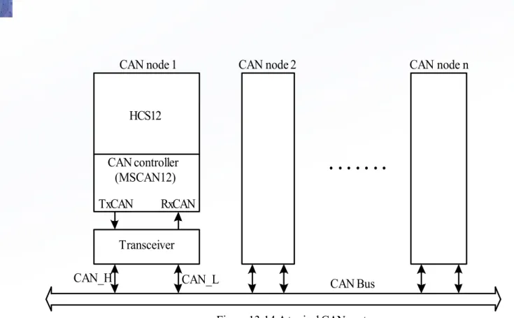
• The block diagram of a CAN module is shown in Figure 13.13.
• The CAN module requires a transceiver (e.g., MCP2551,
PCA82C250) to interface
with the CAN bus.
MUX Oscillator clock
Bus clock Prescaler
CANCLK
Control and Status
Configuration registers
Receive/ Transmit
Engine
Message filtering
and buffering Tx int. req.
Rx int. req. Err. int. req. Wake-up int. req.
RxCAN
HCS12
CAN controller (MSCAN12)
TxCAN RxCAN
Transceiver
CAN_H CAN_L
CAN node 1 CAN node 2 CAN node n
. . . .
MSCAN Module Memory Map
• Each CAN module occupies 64 bytes of memory space.
• The MSCAN register organization is shown in Figure
13.15.
• Each receive buffer and each transmit buffer occupies
16 bytes of space.
address register name access $_00 $_01 $_02 $_03 $_04 $_05 $_06 $_07 $_08 $_09 $_0A $_0B $_0C $_0D $_0E $_0F $_10 $_11 $_12 $_13 $_14 $_15 $_16 $_17 $_18 $_19 $_1A $_1B $_1C $_1D $_1E $_1F $_20 $_2F $_30
MSCAN control register 0 (CANCTL0) MSCAN control register 1 (CANCTL1) MSCAN bus timing register 0 (CANBTR0) MSCAN bus timing register 1 (CANBTR1) MSCAN receiver flag register (CANRFLG)
MSCAN receiver interrupt enable register (CANRIER) MSCAN transmitter flag register (CANTFLG)
MSCAN transmitter interrupt enable register (CANTIER) MSCAN transmitter message abort request(CANTARQ) MSCAN transmitter message abort acknowledge (CANTAAK) MSCAN transmit buffer selection (CANTBSEL)
MSCAN identifier acceptance control register (CANIDAC) reserved
reserved
MSCAN receive error counter register (CANRXERR) MSCAN transmit error counter register (CANTXERR) MSCAN identifier acceptance register 0 (CANIDAR0) MSCAN identifier acceptance register 1 (CANIDAR1) MSCAN identifier acceptance register 2 (CANIDAR2) MSCAN identifier acceptance register 3 (CANIDAR3) MSCAN identifier mask register 0 (CANIDMR0) MSCAN identifier mask register 1 (CANIDMR1) MSCAN identifier mask register 2 (CANIDMR2) MSCAN identifier mask register 3 (CANIDMR3) MSCAN identifier acceptance register 4 (CANIDAR4) MSCAN identifier acceptance register 5 (CANIDAR5) MSCAN identifier acceptance register 6 (CANIDAR6) MSCAN identifier acceptance register 7 (CANIDAR7) MSCAN identifier mask register 4 (CANIDMR4) MSCAN identifier mask register 5 (CANIDMR5) MSCAN identifier mask register 6 (CANIDMR6) MSCAN identifier mask register 7 (CANIDMR7)
R/ W R/ W R/ W R/ W R/ W R/ W R/ W R/ W R/ W R R/ W R/ W R R R/ W R/ W R/ W R/ W R/ W R/ W R/ W R/ W R/ W R/ W R/ W R/ W R/ W R/ W R/ W R/ W
MSCAN Control Registers
• Motorola names each CAN register as CANxYYYY, where x
indicates the CAN module and YYYY specifies the register.
• MSCAN Control Register 0 (CANxCTL0)
– Bits 7, 6, and 4 are status flags. Other bits are control bits. Status bits
are read-only.
– When the TIME bit is set to 1, the timer value will be assigned to each
transmitted and received message within the transmit and receive
buffers.
– In order to configure the CANxCTL1, CANxBTR0, CANxBTR1,
RXFRM RXACT CSWAI SYNCH TIME WUPE SLPRQ INITRQ 0 1 2 3 4 5 6 7
0 0 0 0 0 0 0 1
reset:
RXFRM: Received frame flag
0 = no valid message was received
1 = a valid message was received since last clearing of this flag RXACT: Receiver active status
0 = MSCAN is transmitting or idle
1 = MSCAN is receiving a message (including when arbitration is lost) CSWAI: CAN stops in wait mode
0 = the module is not affected during wait mode 1 = the module ceases to be clocked during wait mode SYNCH: synchronization status
0 = MSCAN is not synchronized to the CAN bus 1 = MSCAN is synchronized to the CAN bus TIME: Timer enable
0 = disable internal MSCAN timer
1 = enable internal MSCAN timer and hence enable time stamp WUPE: Wake-up enable
0 = wake-up disabled (MSCAN ignores traffic on CAN bus) 1 = wake-up enabled (MSCAN is able to restart)
SLPRQ: Sleep mode request
0 = running--The MSCAN functions normally
1 = sleep mode request--The MSCAN enters sleep mode when CAN is idle INITRQ: Initialization mode request
0 = normal operation
CANE CLKSRC LOOPB LISTEN 0 WUPM SLPAK INITAK 0 1 2 3 4 5 6 7
0 0 0 1 0 0 0 1
reset:
CANE: MSCAN enable
0 = The MSCAN module is disabled. 1 = The MSCAN module is enabled. CLKSRC: MSCAN clock source
0 = The MSCAN clock source is the oscillator clock. 1 = The MSCAN clock source is the bus clock. LOOPB: Loop back self test mode
0 = Loop back self test disabled 1 = Loop back self test enabled LISTEN: Listen only mode 0 = Normal operation
1 = Listen only mode activated. WUPM: Wake-up mode
0 = MSCAN wakes up the CPU after any recessive to dominant edge on the CAN bus and WUPE bit of the CANCTL0 register is set to 1.
1 = MSCAN wakes up the CPU only in case of a dominant pulse on the CAN
SJW1 SJW0 BRP5 BRP4 BRP3 BRP2 BRP1 BRP0 0 1 2 3 4 5 6 7
0 0 0 0 0 0 0 0
reset:
SJW1, SJW0: Synchronization jump width 00 = 1 Tq clock cycle
01 = 2 Tq clock cycle 10 = 3 Tq clock cycle 11 = 4 Tq clock cycle
BRP5~BRP0: Baud rate prescaler 000000 = 1
000001 = 2 000010 = 3 ....
111110 = 63 111111 = 64
Figure 13.19 MSCAN bus timeing register 0 (CANxBTR0, x = 0, 1, 2, 3, or 4)
MSCAN Bus Timing Register 0 (CANxBTR0)
prescaler value
Bit time = --- (1 + TimeSegment1 + TimeSegment2) fCANCLK
SAMP TSEG22 TSEG21 TSEG20 TSEG13 TSEG12 TSEG11 TSEG10 0 1
2 3
4 5
6 7
0 0 0 0 0 0 0 0
reset:
SAMP: Sampling
0 = One sample per bit 1 = Three samples per bit TSEG22~TSEG20: Time segment 2 000 = 1 Tq clock cycle
001 = 2 Tq clock cycles ....
110 = 7 Tq clock cycles
MSCAN Bus Timing Register 1 (CANxBTR1)
•
This register provides control on phase_seg1 and phase_seg2.
WUPIF CSCIF RSTAT1 RSTAT0 TSTAT1 TSTAT0 OVRIF RXF 0 1 2 3 4 5 6 7
0 0 0 0 0 0 0 0
reset:
WUPIF: Wake-up interrupt flag
0 = No wake-up activity observed while in sleep mode
1 = MSCAN detected activity on the bus and requested wake-up CSCIF: CAN status change interrupt flag
0 = No change in bus status occurred since last interrupt 1 = MSCAN changed current bus status
RSTAT1~RSTAT0: Receiver status bits
00 = RxOK: 0 Receive error counter 96 01 = RxWRN:96 < Receive error counter 127 10 = RxERR: 127 < Receive error counter 11 = Bus-off1: Transmit error counter > 255
TSTAT1~TSTAT0: Transmitter status bits 00 = TxOK: 0 Transmit error counter 96 01 = TxWRN: 96 < Transmit error counter 127 10 = TxERR: 127 < Transmit error counter 11 = Bus-off: Transmit error counter > 255 OVRIF: Overrun interrupt flag
0 = No data overrun occurred 1 = A data overrun detected RXF: Receive buffer full flag
0 = No new message availale within the RxFG
1 = The receive FIFO is not empty. A new message is available in the RxFG.
MSCAN Receiver Flag Register (CANxRFLG)
•
The flag bits WUPIF, CSCIF, OVRIF, and RXF are cleared by writing a “1”
WUPIE CSCIE RSTATE1RSTATE0 TSTATE1TSTATE0 OVRIE RXFIE 0 1 2 3 4 5 6 7
0 0 0 0 0 0 0 0
reset:
WUPIE: Wake-up interrupt enable
0 = No interrupt request is generated from this event 1 = A wake-up event causes a wake-up interrupt request CSCIE: CAN status change interrupt enable
0 = No interrupt request is generated from this event
1 = A CAN status change event causes an error interrupt request RSTATE1~RSTATE0: Receiver status change interrupt enable
00 = do not generate any CSCIF interrupt caused by receiver state changes 01 = generate CSCIF interrupt only if the receiver enters or leaves "bus-off" state.
10 = generate CSCIF interrupt only if the receiver enters or leaves "RxErr" or "Bus-Off" state
11 = generate CSCIF interrupt on all state changes
TSTATE1~TSTATE0: Transmitter status change interrupt enable
00 = do not generate any CSCIF interrupt caused by transmitter state changes 01 = generate CSCIF interrupt only if the transmitter enters or leaves off" state.
10 = generate CSCIF interrupt only if the transmitter enters or leaves
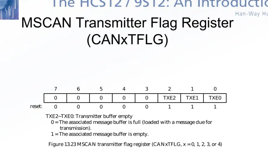
0 0 0 0 0 TXE2 TXE1 TXE0 0 1
2 3
4 5
6 7
0 0 0 0 0 1 1 1
reset:
TXE2~TXE0: Transmitter buffer empty
0 = The associated message buffer is full (loaded with a message due for transmission).
1 = The associated message buffer is empty.
Figure 13.23 MSCAN transmitter flag register (CANxTFLG, x = 0, 1, 2, 3, or 4)
0 0 0 0 0 TXEIE2 TXEIE1 TXEIE0 0 1
2 3
4 5
6 7
0 0 0 0 0 0 0 0
reset:
TXEIE2~TXEIE0: Transmitter empty interrupt enable 0 = Disable interrupt from this buffer.
1 = A transmitter empty event causes a transmitter empty interrupt request. Figure 13.24 MSCAN transmitter interrupt enable register (CANxTIER, x = 0, 1, 2, 3, or 4)
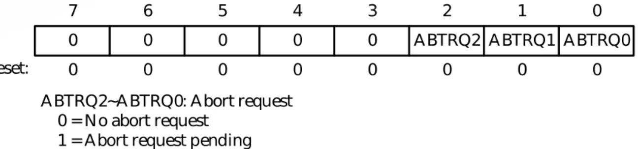
0 0 0 0 0 ABTRQ2 ABTRQ1 ABTRQ0 0 1
2 3
4 5
6 7
0 0 0 0 0 0 0 0
reset:
ABTRQ2~ABTRQ0: Abort request 0 = No abort request
1 = Abort request pending
Figure 13.25 MSCAN transmitter message abort request register (CANxTARQ, x = 0, 1, 2, 3, or 4)
MSCAN Transmitter Message Abort
Request Register (CANxARQ)
0 0 0 0 0 ABTAK2 ABTAK1 ABTAK0 0 1
2 3
4 5
6 7
MSCAN Transmit Message Abort Acknowledge
Register (CANxTAAK)
• A message that is being transmitted cannot be aborted.
• Only those messages that have not been transmitted
can be aborted.
0 0 0 0 0 TX2 TX1 TX0 0 1
2 3
4 5
6 7
0 0 0 0 0 0 0 0
reset:
TX2~TX0: Transmit buffer select bits
0 = The associated message buffer is deselected.
1 = The associated message buffer is selected, if it is the lowest numbered bit.
MSCAN Transmit Buffer Selection
(CANxTBSEL)
• This register selects the actual message buffer
that will be accessible in the CANTxFG register
space.
ldaa CANxTFLG ; assume value read is %00000111 staa CANxTBSEL ; value written is %00000111
Method to Identify an Empty
Transmit Buffer for Data Transmission
• Reads the CANxTFLG register and then writes it into the
CANxTBSEL register.
0 0 IDAM1 IDAM0 0 IDHIT2 IDHIT1 IDHIT0 0 1 2 3 4 5 6 7
0 0 0 0 0 0 0 0
reset:
IDAM1~IDAM0: Identifier acceptance mode 00 = Two 32-bit acceptance filters
01 = Four 16-bit acceptance filters 10 = Eight 8-bit acceptance filters 11 = Filter closed
IDHIT2~IDHIT0: Identifier acceptance hit indicator (read only) 000 = Filter 0 hit
001 = Filter 1 hit 010 = Filter 2 hit 011 = Filter 3 hit 100 = Filter 4 hit 101 = Filter 5 hit 110 = Filter 6 hit 111 = Filter 7 hit
MSCAN Identifier Acceptance
Register (CANxIDAC)
•
This register provides for identifier acceptance control.
AC7 AC6 AC5 AC4 AC3 AC2 AC1 AC0 0 1 2 3 4 5 6 7
0 0 0 0 0 0 0 0
reset:
CANxIDAR0
AC7 AC6 AC5 AC4 AC3 AC2 AC1 AC0 0 1 2 3 4 5 6 7
0 0 0 0 0 0 0 0
reset:
CANxIDAR1
AC7 AC6 AC5 AC4 AC3 AC2 AC1 AC0 0 1 2 3 4 5 6 7 CANxIDAR2
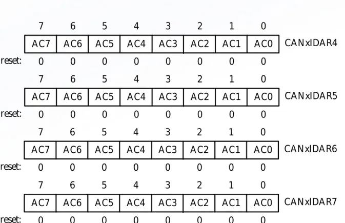
MSCAN Identifier Acceptance
Registers (CANxIDAR0~7)
• On reception, each message is written into the background receive buffer.
• The CPU is only signaled to read the message if it passes the criteria in the identifier acceptance and identifier mask registers.
AC7 AC6 AC5 AC4 AC3 AC2 AC1 AC0 0 1 2 3 4 5 6 7
0 0 0 0 0 0 0 0
reset:
Figure 13.30 MSCAN Identifier acceptance registers (second bank) (x = 0, 1, 2, 3, or 4)
CANxIDAR4
AC7 AC6 AC5 AC4 AC3 AC2 AC1 AC0
0 1 2 3 4 5 6 7
0 0 0 0 0 0 0 0
reset:
CANxIDAR5
AC7 AC6 AC5 AC4 AC3 AC2 AC1 AC0
0 1 2 3 4 5 6 7
0 0 0 0 0 0 0 0
reset:
CANxIDAR6
AC7 AC6 AC5 AC4 AC3 AC2 AC1 AC0
0 1 2 3 4 5 6 7
0 0 0 0 0 0 0 0
reset:
AM7 AM6 AM5 AM4 AM3 AM2 AM1 AM0 0 1 2 3 4 5 6 7
0 0 0 0 0 0 0 0
reset:
CANxIDMR0
AM7 AM6 AM5 AM4 AM3 AM2 AM1 AM0 0 1 2 3 4 5 6 7
0 0 0 0 0 0 0 0
reset:
CANxIDMR1
AM7 AM6 AM5 AM4 AM3 AM2 AM1 AM0 0 1 2 3 4 5 6 7 CANxIDMR2
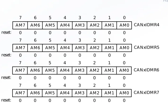
MSCAN Identifier
Mask Registers (CANxIDMR0~7)
•
The identifier mask registers specify which of the corresponding bits in the
identifier acceptance registers are relevant for acceptance filtering.
AM7 AM6 AM5 AM4 AM3 AM2 AM1 AM0 0 1 2 3 4 5 6 7
0 0 0 0 0 0 0 0
reset:
Figure 13.32 MSCAN Identifier mask registers (second bank) (x = 0, 1, 2, 3, or 4)
CANxIDMR4
AM7 AM6 AM5 AM4 AM3 AM2 AM1 AM0
0 1 2 3 4 5 6 7
0 0 0 0 0 0 0 0
reset:
CANxIDMR5
AM7 AM6 AM5 AM4 AM3 AM2 AM1 AM0
0 1 2 3 4 5 6 7
0 0 0 0 0 0 0 0
reset:
CANxIDMR6
AM7 AM6 AM5 AM4 AM3 AM2 AM1 AM0
0 1 2 3 4 5 6 7
0 0 0 0 0 0 0 0
reset:
address register name $_x0 $_x1 $_x2 $_x3 $_x4 $_x5 $_x6 $_x7 $_x8 $_x9 $_xA $_xB
Identifier register 0 Identifier register 1 Identifier register 2 Identifier register 3 Data segment register 0 Data segment register 1 Data segment register 2 Data segment register 3 Data segment register 4 Data segment register 5 Data segment register 6 Data segment register 7
MSCAN Message Buffers
• The receive message and transmit message buffers have the same
outline.
ID28 ID27 ID26 ID25 ID24 ID23 ID22 ID21 ID20 ID19 ID18 SRR(=1)IDE(=1) ID17 ID16 ID15
ID14 ID13 ID12 ID11 ID10 ID9 ID8 ID7
ID6 ID5 ID4 ID3 ID2 ID1 ID0 RTR
7 6 5 4 3 2 1 0
Figure 13.34 Receive/ transmit message buffer extended identifier IDR0
IDR1 IDR2 IDR3
ID10 ID9 ID8 ID7 ID6 ID5 ID4 ID3
ID2 ID1 ID0 RTR IDE(=0)
7 6 5 4 3 2 1 0
IDR0 IDR1 IDR2 IDR3
Identifier Registers (IDR0~IDR3)
• All four identifier registers are compared when a message with
extended identifier is received.
• Data Segment Registers (DSR0~DSR7)
– These registers contain the data to be transmitted or received.
– The number of bytes to be transmitted or received is determined by the
data length code.
• Data Length Register (DLR)
– The lowest four bits of this register indicate the number of bytes
contained in the message.
• Transmit Buffer Priority Register (TBPR)
– This register defines the local priority of the associated message buffer.
– All transmit buffer with a cleared TXEx flag participate in the
prioritization.
TSR15 TSR14 TSR13 TSR12 TSR11 TSR10 TSR9 TSR8 0 1 2 3 4 5 6 7
x x x x x x x x
reset:
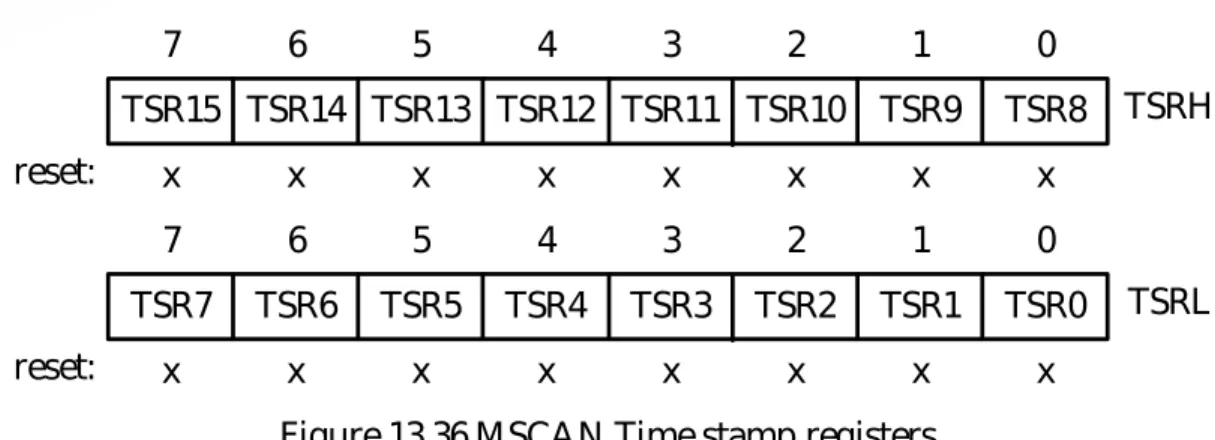
Figure 13.36 MSCAN Time stamp registers
TSRH
TSR7 TSR6 TSR5 TSR4 TSR3 TSR2 TSR1 TSR0 0 1 2 3 4 5 6 7
x x x x x x x x
reset:
TSRL
Time Stamp Register (TSRH, TSRL)
• If the TIME bit of CANxCTL0 is set to 1, the MSCAN will write a special
time
stamp to the respective registers in the active transmit or receive
buffer as soon as a message has been acknowledged.
Table 13.2a CAN foreground receive buffer x variable names
Name Address Description
CANxRIDR0 CANxRIDR1 CANxRIDR2 CANxRIDR3 CANxRDSR0 CANxRDSR1 CANxRDSR2 CANxRDSR3 CANxRDSR4 CANxRDSR5 CANxRDSR6 CANxRDSR7 $_0 $_1 $_2 $_3 $_4 $_5 $_6 $_7 $_8 $_9 $_A $_B
CAN foreground receive buffer x identifier register 0 CAN foreground receive buffer x identifier register 1 CAN foreground receive buffer x identifier register 2 CAN foreground receive buffer x identifier register 3 CAN foreground receive buffer x data segment register 0 CAN foreground receive buffer x data segment register 1 CAN foreground receive buffer x data segment register 2 CAN foreground receive buffer x data segment register 3 CAN foreground receive buffer x data segment register 4 CAN foreground receive buffer x data segment register 5 CAN foreground receive buffer x data segment register 6 CAN foreground receive buffer x data segment register 7
Can Foreground Receive
Table 13.2b CAN foreground transmit buffer x variable names Name Address Description
CANxTIDR0 CANxTIDR1 CANxTIDR2 CANxTIDR3 CANxTDSR0 CANxTDSR1 CANxTDSR2 CANxTDSR3 CANxTDSR4 CANxTDSR5 CANxTDSR6 CANxTDSR7 CANxTDLR CANxTBPR CANxTSRH CANxTSRL $_0 $_1 $_2 $_3 $_4 $_5 $_6 $_7 $_8 $_9 $_A $_B $_C $_D $_E $_F
CAN foreground transmit buffer x identifier register 0 CAN foreground transmit buffer x identifier register 1 CAN foreground transmit buffer x identifier register 2 CAN foreground transmit buffer x identifier register 3 CAN foreground transmit buffer x data segment register 0 CAN foreground transmit buffer x data segment register 1 CAN foreground transmit buffer x data segment register 2 CAN foreground transmit buffer x data segment register 3 CAN foreground transmit buffer x data segment register 4 CAN foreground transmit buffer x data segment register 5 CAN foreground transmit buffer x data segment register 6 CAN foreground transmit buffer x data segment register 7 CAN foreground transmit buffer x data length register CAN foreground transmit buffer x priority register
CAN foreground transmit buffer x time stamp register high CAN foreground transmit buffer x time stamp register low Note 1. x can be 0, 1, 2, or 3
2. The absolute address of each register is equal to the sum of the base
Tx0 Tx1 Tx2 T xF G T xB G PRIO PRIO TXE0 TXE1 TXE2 CPU bus MSCAN
Transmit Storage Structure
• Multiple messages
can be set up in
advance and achieve
real-time
performance.
• A transmit buffer is
made accessible to
the user by writing
appropriate value into
the CANxTBSEL
register.
Procedure for Message Transmission
• Step 1
– Identifying an available transmit buffer by checking the TXEx flag
associated with the transmit buffer.
• Step 2
– Setting a pointer to the empty transmit buffer by writing the
CANxTFLG register to the CANxTBSEL register. This makes the
transmit buffer accessible to the user.
• Step 3
– Storing the identifier, the control bits, and the data contents into
one of the transmit buffers.
• Step 4
RX4 RX3 RX2 RX1 RX0 R xB G R xF G RXF CPU bus MSCAN
Figure 13.38 User model for receive buffer organization
Receive Storage Structure
(1 of 2)
• Received messages
are stored in a
five-stage FIFO data
structure.
• The message buffers
are alternately mapped
into a single memory
area referred to as the
foreground receive
buffer.
Receive Storage Structure
(2 of 2)
• When a valid message is received at the background
receive buffer, it will be transferred to the foreground
receive buffer and the RXF flag will be set to 1.
• The user’s program has to read the received message
from the RxFG and then clear the RXF flag to
acknowledge the interrupt and to release the foreground
receive buffer.
Identifier Acceptance Filter
•
Identifier acceptance registers define the acceptance patterns of the
standard or extended identifier.
•
Any of the bits in the acceptance identifier can be marked “don’t care” in the
MSCAN identifier mask registers.
•
A message is accepted only if its associated identifier matches one of the
identifier filters.
•
A filter hit is indicated by setting a RXF flag to 1 and the three hit bits in the
CANIDAC register.
•
The identifier acceptance filter can be programmed to operate in one of the
four modes:
f
= f
prescaler
Bus clock
Oscillator clock
CLKSRC
Prescaler (1...64) MSCAN
Time quanta clock (Tq)
CLKSRC
CANCLK
Figure 13.39 MSCAN clocking scheme
MSCAN Clock System
•
Either the bus clock or the crystal oscillator output can be used as the
CANCLK.
•
The clock source has to be chosen so that it meets the 0.4% tolerance
requirement of the CAN protocol.
•
If the bus clock is generated from a PLL, it is recommended to select the
oscillator clock rather than the bus clock due to the jitter considerations,
especially at the higher baud rate.
NRZ signal
SYNC_SEG Time segment 1
(prop_seg + phase_seg1)
Time segment 2 (phase_seg2)
MSCAN Bit Time
• MSCAN divides a bit time into three segments:
– Sync_seg: fixed at one time quantum
– Time segment 1: This segment includes the prop_seg
and phase_seg1 of the CAN standard.
MSCAN Interrupt Operation
• Transmit interrupt
– At least one of the three transmit buffers is empty, its TXEx flag is set.
• Receive interrupt
– When a message is successfully received and shifted to the foreground
buffer of the receive FIFO. The associated RXF flag is set.
• Wakeup interrupt
– Activity on the CAN bus occurred during the MSCAN internal sleep
mode generates this type of interrupts.
• Error interrupt
MSCAN Initialization
• Procedure of MSCAN Initialization Out of Reset
– Assert the CANE bit
– Enter the initialization mode (make sure both the INITRQ and INITAK
bits are set)
– Write to the configuration registers including CANxCTL1, CANxBTR0,
CANxBTR1, CANxIDAC, CANxIDAR0-7, CANxIDMR0-7.
– Clear the INITRQ bit to leave the initialization mode and enter normal
mode.
• Procedure of MSCAN Initialization in Normal Mode
RT = 120
node 1
node 2
node 3
node n
CAN_H
RT (120
Physical CAN Bus Connection
• CAN is designed for data communication over a short
distance.
• CAN protocol does not specify what medium to use for
data communication.
• Using a shielded or unshielded cable is recommended
for a short distance communication.
CAN_H
CAN_L 2.5V
1.5V 3.5V 5V
voltage
Slope control Reference Voltage Receiver Driver control Thermal shutdown CANH CANL 2 7 6 VREF RxD Rs 5 4 8 1 TxD VDD 3 TXD Dominant Detect VDD
power-on reset VDD
GND
Microchip MCP2551 CAN Bus Transceiver
(2 of 3)
• MCP2551 provides a differential transmit and receive capability.
• Operates up to 1 Mbps data rate
• Allows a maximum of 112 nodes to be connected to the same CAN
bus.
• The RxD pin reflects the differential voltage between CAN_H and
CAN_L.
• The Rs input allows the user to select one of the three operation
modes:
– High speed – ground the Rs pin
25
20
15
10
5
0
Sl
ew
r
at
e
V
/u
S
10 20 30 40 49 60 70 80 90 100 110
Resistance (K)
Figure 13.44 Slew rate vs. slope control resistance value
TXCAN RXCAN
TxD RxD VREF RS R
EXT
CAN_H
CANH CANL
5V VCC
100nF
GND
MCP2551 HCS12
REXT set to 0 in high-speed mode
Table 13.3 CAN bus bit rate /bus length relation Bit rate (kbit/s) Bus length
1000 500 250 125 62.5
40 100 250 500 1000
Setting the CAN Timing Parameters
(1 of 2)
• Let t
BUS, t
TX, and t
RXrepresent the data traveling
time on the bus, transmitter propagation delay,
and receiver propagation delay, respectively.
– The worst-case value for t
PROP_SEGis
t
PROP_SEG= 2
(t
BUS+ t
TX+ tRX)
(13.4)
– In units of time quantum,
Setting the CAN Timing Parameters
(2 of 2)
• In the absence of bus errors, bit stuffing guarantees a maximum
10-bit period between resynchronization edges.
• The accumulated phase errors are due to the tolerance in the CAN
system clock. This requirement can be expressed as
(2 f) 10 tNBT < tRJW (13.6)
where, f is the largest crystal oscillator frequency variation.
• When bus error exists, an error flag from an error active node
Procedure for Determining
the Optimum Bit Timing Parameters
(1 of 2)
• Step 1
– Determine the minimum permissible
t
prop_segusing equation 13.4.
• Step 2
– Choose the
CAN system clock frequency
. The CAN system
clock frequency will be either the CPU oscillator output or the
bus clock divided by a prescale factor. The chosen clock
frequency must make the tNBT an integral multiple of tQ from 8
to 25.
• Step 3
– Calculate the
prop_seg
duration using equation 13.5
.
If the
Procedure for Determining
the Optimum Bit Timing Parameters
(2 of 2)
• Step 4
– Determine
phase1_seg
and
phase_seg2
. Subtract the prop_seg value
and 1 from the time quanta contained in a bit time. If the difference is
less than 3 than go back to Step 2 and select a higher CAN system
clock frequency. If the difference is 3, then phase_seg1 = 1 and
phase_seg2 = 2 and only one sample per bit may be chosen. If the
difference is an odd number greater than 3, then add 1 to the prop_seg
value and recalculate. Otherwise divide the remaining number by two
and assign the result to phase_seg1 and phase_seg2.
• Step 5
•
Example 13.1
Calculate the CAN bit segments for the following constraints:
– Bit rate = 1 Mbps– Bus length = 25 m
– Bus propagation delay = 5 10-9 sec/m
– CAN transceiver plus receiver propagation delay = 150 ns at 85oC – CPU oscillator frequency = 24 MHz
•
Solution:
– Step 1Physical delay of the CAN bus = 25 5 = 125 ns tPROP_SEG = 2 (125 + 150) = 550 ns
– Step 2
A prescaler of 1 for 24 MHz gives a time quantum of 41.67 ns. One bit time is 1/1 Mbps = 1 s.
– Step 3
Prop_seg = round_up (550 ns 41.67) = 14 > 8. Set prescaler to 2. Then one time quantum is 83.33 ns and one bit time is 12 time quanta. The new prop_seg = 7. – Step 4
NBT – prop_seg1 – sync_seg = 12 – 7 – 1 = 4. phase_seg1 = 4/2 = 2,
phase_seg2 = 4 – phase_seg1 = 2 – Step 5
RJW = min (4, phase_seg1) = 2 – Step 6
From equation 13.7,
f < RJW (20 NBT) = 2 (20 12) = 0.83%
From equation 13.8,
• Most crystal oscillators have tolerance smaller than 0.65%.
•In
summary
,
Prescaler = 2
Nominal bit time = 12
prop_seg = 7
sync_seg = 1
phase_seg1 = 2
phase_seg2 = 2
RJW = 2
• Example 13.2 Calculate the CAN bit segments for the following constraints: – Bit rate = 500 Kbps
– Bus length = 50 m
– Bus propagation delay = 5 10-9 sec/m
– CAN transceiver plus receiver propagation delay = 150 ns at 85oC – CPU oscillator frequency = 16 MHz
• Solution:
– Step 1
Physical delay of the bus = 50 5 10-9 sec/m = 250 ns tPROP_SEG = 2 (250 + 150) = 800 ns
– Step 2
Use 2 as the prescaler.
– Step 5
RJW = min (4, phase_seg1) = 4 – Step 6
From equation 13.6,
f < RJW (20 NBT) = 4 (20 16) = 1.25% From equation 13.7,
f < min(phase_seg1, phase_seg2) [2 (13 NBT – phase_seg2)] = 4 408= 0.98%
•
In summary
,
Prescaler = 2
Nominal bit time = 16
Prop_seg = 7
Sync_seg = 1
Phase_seg1 = 4
Phase_seg2 = 4
RJW = 4
openCan1 bset CAN1CTL1,CANE ; required after reset
MSCAN Configuration
•
Timing parameters for the CAN module need only be set once after reset.
•
Other parameters such as acceptance filters may be changed after reset
configuration.
•
Example 13.3 Write a program to configure the MSCAN module 1 after
reset with the timing parameters in Example 13.1 and the following setting:
– Enable wakeup – Disable time stamp
– Select oscillator as the clock source to the MSCAN – Disable loopback mode, disable listen only mode – Take one sample per bit
– Acceptance messages with extended identifiers that start with T1 and P1 (use two 32-bit filters)
movb #$41,CAN1BTR0 ; set jump width to 2 Tq, prescaler set to 2
movb #$18,CAN1BTR1 ; set phase_seg2 to 2 Tq, phase_seg1 to 2 Tq, ; set prop_seg to 7 Tq
movb #$54,CAN1IDAR0 ; acceptance identifier 'T'
movb #$3C,CAN1IDAR1 ; acceptance identifier '1‘ (IDE bit = 1) movb #$40,CAN1IDAR2 ; "
movb #$00,CAN1IDAR3 ; "
movb #$00,CAN1IDMR0 ; acceptance mask for extended identifier "T1" movb #$00,CAN1IDMR1 ; "
movb #$3F,CAN1IDMR2 ; " movb #$FF,CAN1IDMR3 ; "
movb #$50,CAN1IDAR4 ; acceptance identifier 'P'
movb #$3C,CAN1IDAR5 ; acceptance identifier '1‘ (IDE bit = 1) movb #$40,CAN1IDAR6 ; "
movb #$00,CAN1IDAR7 ; "
movb #$00,CAN1IDMR4 ; acceptance mask for extended identifier "P1" movb #$00,CAN1IDMR5 ; "
movb #$3F,CAN1IDMR6 ; " movb #$FF,CAN1IDMR7 ; "
clr CAN1IDAC ; set two 32-bit filter mode
void openCan1(void) {
CAN1CTL1 |= CANE; /* enable CAN, required after reset */ CAN1CTL0 |= INITRQ; /* request to enter initialization mode */
while(!(CAN1CTL1&INITAK)); /* wait until initialization mode is entered */ CAN1CTL1 = 0x84; /* enable CAN1, select oscillator as MSCAN clock source, enable wakeup filter */
CAN1BTR0 = 0x41; /* set SJW to 2, set prescaler to 2 */
CAN1BTR1 = 0x18; /* set phase_seg2 to 2Tq, phase_seg1 to 2Tq, prop_seg to 7 Tq */
CAN1IDAR0 = 0x54; /* set acceptance identifier "T1" */ CAN1IDAR1 = 0x3C; /* " */
CAN1IDAR2 = 0x40; /* " */ CAN1IDAR3 = 0x00; /* " */
CAN1IDAR6 = 0x40; /* " */ CAN1IDAR7 = 0x00; /* " */
CAN1IDMR4 = 0x00; /* acceptance mask for "P1" */ CAN1IDMR5 = 0x00; /* " */
CAN1IDMR6 = 0x3F; /* " */ CAN1IDMR7 = 0xFF; /* " */
CAN1IDAC = 0x00; /* select two 32-bit filter mode */ CAN1CTL0 &= ~INITRQ; /* exit initialization mode *
CAN1CTL0 = 0x24; /* stop clock on wait mode, enable wake up */ }
• Example 13.4 Write an instruction sequence to change the configuration of the CAN1 module so that it would accept messages with standard identifier starting with letter ‘T’ or ‘P’.
• Solution:
ct1 brset CAN1TFLG,$07,tb_empty ; wait until all transmit buffers are empty bra ct1
tb_empty bset CAN1CTL0,SLPRQ ; request to enter sleep mode
ct2 brclr CAN1CTL1,SLPAK,ct2 ; wait until sleep more is entered bset CAN1CTL0,INITRQ ; request to enter initialization mode
ct3 brclr CAN1CTL1,INITAK,ct3 ; wait until initialization mode is entered movb #$10,CAN1IDAC ; select 4 16-bit acceptance mode
movb #$54,CAN1IDAR0 ; set up filter for letter 'T' for standard movb #0,CAN1IDAR1 ; identifier (IDE bit = 0)
movb #$50,CAN1IDAR2 ; set up filter for letter 'P' for standard clr CAN1IDAR3 ; identifier (IDE bit = 0)
clr CAN1IDMR0 ; acceptance mask for 'T'
movb #$F7,CAN1IDMR1 ; check IDE bit only (must be 0)
clr CAN1IDAR7 ; identifier
clr CAN1IDMR4 ; acceptance mask for 'T'
movb #$F7,CAN1IDMR5 ; check IDE bit only (must be 0) clr CAN1IDMR6 ; acceptance mask for 'P'
movb #$F7,CAN1IDMR7 ; check IDE bit only (must be 0) bclr CAN1CTL0,INITRQ ; exit initialization mode
tbuf equ 0 ; tbuf offset from top of stack
snd2can1 pshy pshb
leas -1,sp ; allocate one byte for local variable sloop1 brset CAN1TFLG,$01,tb0 ; is transmit buffer 0 empty?
Data Transmission and Reception in MSCAN
•
Data transmission in CAN bus can be driven by polling method or interrupts.
•
When data to be transmitted is small and infrequent, polling method is quite
good.
•
Data arrival is usually less predictable. It is more convenient to use
interrupt-driven method for data reception.
– Example 13.5 Write a function to send out the message stored at a buffer pointed to by index register X from the CAN1 module. The function should find an
tb1 movb #1,tbuf,sp ; mark transmit buffer 1 empty
bra tcopy
tb2 movb #2,tbuf,sp ; mark transmit buffer 2 empty
tcopy movb CAN1TFLG,CAN1TBSEL ; make the empty transmit buffer accessible ldy #CAN1TIDR0 ; set y to point to the start of the transmit buffer ldab #7 ; always copy 7 words (place word count in B) cploop movw 2,x+,2,y+
dbne b,cploop ldab tbuf,sp cmpb #0
beq istb0
cmpb #1
beq istb1
movb #$04,CAN1TFLG ; mark buffer 2 ready for transmission
bra dcopy
istb0 movb #$01,CAN1TFLG ; mark buffer 0 ready for transmission
bra dcopy
istb1 movb #$02,CAN1TFLG ; mark buffer 1 ready for transmission dcopy leas 1,sp ; deallocate local variables
void snd2can1(char *ptr) {
int tb,i,*pt1,*pt2;
pt1 = (int *)ptr; /* convert to integer pointer */ while(1) { /* find an empty transmit buffer */ if(CAN1TFLG & 0x01){
tb = 0; break; }
if(CAN1TFLG & 0x02){ tb = 1;
break; }
if(CAN1TFLG & 0x04){
for (i = 0; i < 7; i++) /* copy the whole transmit buffer */ *pt2++ = *pt1++;
if (tb == 0)
CAN1TFLG = 0x01; /* mark buffer 0 ready for transmission */ else if (tb == 1)
CAN1TFLG = 0x02; /* mark buffer 1 ready for transmission */ else
•
Example 13.6
Write a program to send out the string “3.5 V” from CAN1
and use “V1” as its identifier. Set transmit buffer priority to the highest.
•
Solution:
org $1000
tbuf0 ds 16
org $1500
movb #$56,tbuf0 ; identifier V1 movb #$3C,tbuf0+1 ; "
movb #$40,tbuf0+2 ; "
movb #0,tbuf0+3 ; “
movb #$34,tbuf0+4 ; data "3" movb #$2E,tbuf0+5 ; data "." movb #$35,tbuf0+6 ; data "5" movb #$20,tbuf0+7 ; data " " movb #$56,tbuf0+8 ; data "V"
#include “c:\egnu091\include\hcs12.h” void snd2can1(char *ptr);
int main(void) {
char tbuf0[16];
tbuf0[0] = 'V'; /* identifier V1 */ tbuf0[1] = 0x3C; /* " */ tbuf0[2] = 0x40; /* " */ tbuf0[3] = 0; /* " */ tbuf0[4] = '3'; /* letter 3 */ tbuf0[5] = '.'; /* character . */ tbuf0[6] = '5'; /* letter 5 */ tbuf0[7] = 0x20; /* space */ tbuf0[8] = 'V'; /* letter V */ tbuf0[12] = 5; /* data length */ tbuf0[13] = 0; /* tbuf0 priority */ snd2can1(tbuf0);
•
Example 13.7
Assuming that the CAN1 receiver has been set up to
accept messages with extended identifiers “T1” and “V1”. The filter 0 is set
up to accept the identifier started with “T1,” whereas the filter 1 is set up to
accept the identifier started with “V1”. Write the interrupt handling routine for
the RXF interrupt. If the acceptance is caused by filter 0, the RXF service
routine would display the following message on a 20
2 LCD:
Temperature is xxx.yoF
If the acceptance of the message is caused by filter 1, the RXF interrupt service routine would display the following message:
Voltage is x.y V
•
Solution:
can1Rx_ISR brset CAN1RFLG,RXF,RxfSet ; is the RXF flag set to 1?
rti ; if not, do nothing
RxfSet ldab CAN1IDAC ; check into IDHIT bits
andb #$07 ; mask out higher 5 bits
beq hit0 ; filter 0 hit?
cmpb #1 ; filter 1 hit?
beq hit1
rti ; not hit 0 nor hit 1, do thing
hit0 ldab CAN1RDLR ; get the byte count of incoming data
beq rxfDone ; byte count 0, return ldx #t1_line1 ; output "Temperature is"
jsr puts2lcd ; "
ldx #CAN1RDSR0
outLoop1 ldaa 1,x+ ; output one byte at a time
jsr putc2lcd ; "
dbne b,outLoop1 ; " rti
hit1 ldab CAN1RDLR ; get the byte count of incoming data
outLoop2 ldaa 1,x+
jsr putc2lcd
dbne b,outLoop2 rxfDone rti
t1_line1 fcc "Temperature is"
dc.b 0
v1_line1 fcc "Voltage is"
#include “c:\egnu091\include\hcs12.h” #include “c:\egnu091\include\vectors12.h” #include “c:\egnu091\include\delay.c”
#include “c:\egnu091\include\lcd_util_SSE256.c” #define INTERRUPT __attribute__((interrupt)) void INTERRUPT RxISR(void);
void openCan1(void);
char *t1Msg = "Temperature is"; char *v1Msg = "Voltage is"; int main (void)
{
UserMSCAN1Rx = (unsigned short) &RxISR; openCan1();
openlcd();
CAN1RIER = 0x01; /* enable CAN1 RXF interrupt only */ asm("cli");
while(1); /* wait for RXF interrupt */
void INTERRUPT RxISR (void) {
char tmp,i,*ptr;
if (!(CAN1RFLG & RXF)) /* interrupt not caused by RXF, return */ return;
tmp = CAN1IDAC & 0x07; /* extract filter hit info */ if (tmp == 0) { /* filter 0 hit */
if (CAN1RDLR==0) /* data length 0, do nothing */ return;
cmd2lcd(0x80); /* set LCD cursor to first row */
puts2lcd(t1Msg); /* output "Temperature is" on LCD */
cmd2lcd(0xC0); /* set LCD cursor to second row */
ptr = (char *)&CAN1RDSR0; /* ptr points to the first data byte */ for (i = 0; i < CAN1RDLR; i++)
cmd2lcd(0xC0); /* set LCD cursor to second row */
ptr = (char *)&CAN1RDSR0; /* PTR points to the first data byte */ for(i = 0; i < CAN1RDLR; i++)
putc2lcd(*ptr++); /* output voltage value on the 2nd row of LCD */ }
•
Example 13.8
Write a C program to be run in a CAN environment using
the same timing parameters as computed in Example 13.1. Each CAN
node measures the voltage (in the range from 0 to 5 V) and sends it out
from the CAN bus and also receives the voltage message sent over the
CAN bus by other nodes. Configure the CAN1 module to receive messages
having an extended identifier started with “V1”. The transmission and
reception are to be proceeded as follows:
- The program measures the voltage of the AN7 pin every 200 milliseconds and sends out the value with identifier “V1”. The voltage is represented in the format of “x.y V”. After sending out a message, the program outputs the following message on the first row of the LCD:
#include “c:\egnu091\include\hcs12.h” #include “c:\egnu091\include\delay.c” #include “c:\egnu091\include\vectors12.h”
#include “c:\egnu091\include\lcd_util_SSE256.c” #define INTERRUPT __attribute__((interrupt)) char *msg1 = "Sent: ";
char *msg2 = "Received: "; void INTERRUPT RxISR(void); void openAD0(void);
void wait20us (void); void OpenCan1(void);
void MakeBuf(char *pt1, char *pt2); void snd2can1(char *ptr);
int main(void) {
char buffer[6]; /* to hold measured voltage */ char buf[16]; /* transmit data buffer */
openlcd(); /* configure LCD kit */
OpenCan1(); /* configure CAN1 module */ buffer[1] = '.'; /* decimal point */
buffer[3] = 0x20; /* space character */ buffer[4] = 'V'; /* volt character */ buffer[5] = 0; /* null character */
openAD0(); /* configure AD0 module */ CAN1RIER = 0x01; /* enable RXF interrupt only */ asm("cli"); /* enable interrupt globally */ while(1) {
ATD0CTL5 = 0x87; /* convert AN7, result right justified */ while(!(ATD0STAT0 & SCF)); /* wait for conversion to complete */ buffer[0] = 0x30 + (ATD0DR0*10)/2046; /* integral digit of voltage */ temp = (ATD0DR0 * 10)%2046; /* find the remainder */
return 0; }
/*******************************************************************************************/ /* The following function formats a buffer into the structure of a CAN transmit */ /* buffer so that it can be copied into any empty transmit buffer for transmission. */ /*******************************************************************************************/ void MakeBuf(char *pt1, char *pt2)
{
char i;
*pt1 = 'V'; /* set "V1" as the transmit identifier */ *(pt1+1) = 0x3C; /* " */
*(pt1+2) = 0x40; /* " */ *(pt1+3) = 0; /* " */
for(i = 4; i < 9; i++) /* copy voltage data */ *(pt1 + i) = *(pt2 + i - 4);
*(pt1+12) = 5; /* set data length to 5 */ }
void INTERRUPT RxISR (void) {
char tmp,i,*ptr;
if (!(CAN1RFLG & RXF)) /* interrupt not caused by RXF, return */ return;
tmp = CAN1IDAC & 0x07; /* extract filter hit info */ if (tmp == 0){ /* filter 0 hit */
if (CAN1RDLR==0) /* if data length is 0, do nothing */ return;
cmd2lcd(0xC0); /* set LCD cursor to second row */ puts2lcd(msg2); /* output "received: " */
ptr = (char *)&CAN1RDSR0; /* ptr points to the first data byte */ for (i = 0; i < CAN1RDLR; i++)
void openAD0 (void) {
int i;
ATD0CTL2 = 0xE0;
delayby10us(2);
ATD0CTL3 = 0x0A; /* perform one conversion */
ATD0CTL4 = 0x25; /* 4 cycles sample time, prescaler set to 12 */ }
void OpenCan1(void) {
CAN1CTL1 |= CANE; /* enable CAN, required after reset */
CAN1CTL0 |= INITRQ; /* request to enter initialization mode */ while(!(CAN1CTL1&INITAK)); /* wait until initialization mode is entered */ CAN1CTL1 = 0x84; /* enable CAN1, select oscillator as MSCAN clock source, enable wakeup filter */
CAN1BTR0 = 0x41; /* set SJW to 2, set prescaler to 2 */
CAN1BTR1 = 0x18; /* set phase_seg2 to 2Tq, phase_seg1 to 2Tq, prop_seg to 7 Tq */
CAN1IDAR3 = 0x00; /* " */
CAN1IDMR0 = 0x00; /* acceptance mask for "V1" */ CAN1IDMR1 = 0x00; /* " */
CAN1IDMR2 = 0x3F; /* " */ CAN1IDMR3 = 0xFF; /* " */
CAN1IDAR4 = 0x00; /* set acceptance identifier NULL */ CAN1IDAR5 = 0x00; /* " */
CAN1IDAR6 = 0x00; /* " */ CAN1IDAR7 = 0x00; /* " */
CAN1IDMR4 = 0x00; /* acceptance mask for NULL */ CAN1IDMR5 = 0x00; /* " */
CAN1IDMR6 = 0x00; /* " */ CAN1IDMR7 = 0x00; /* " */
CAN1IDAC = 0x00; /* select two 32-bit filter mode */ CAN1CTL0 &= ~INITRQ; /* exit initialization mode */
if(CAN1TFLG & 0x01){ tb = 0;
break; }
if(CAN1TFLG & 0x02){ tb = 1;
break; }
if(CAN1TFLG & 0x04){ tb = 2;
break; }
}
CAN1TBSEL = CAN1TFLG; /* make empty transmit buffer accessible */ pt2 = (int *)&CAN1TIDR0; /* pt2 points to the IDR0 of TXFG */
for (i = 0; i < 7; i++) /* copy the whole transmit buffer */ *pt2++ = *pt1++;
if (tb == 0)
CAN1TFLG = 0x01; /* mark buffer 0 ready for transmission */ else if (tb == 1)